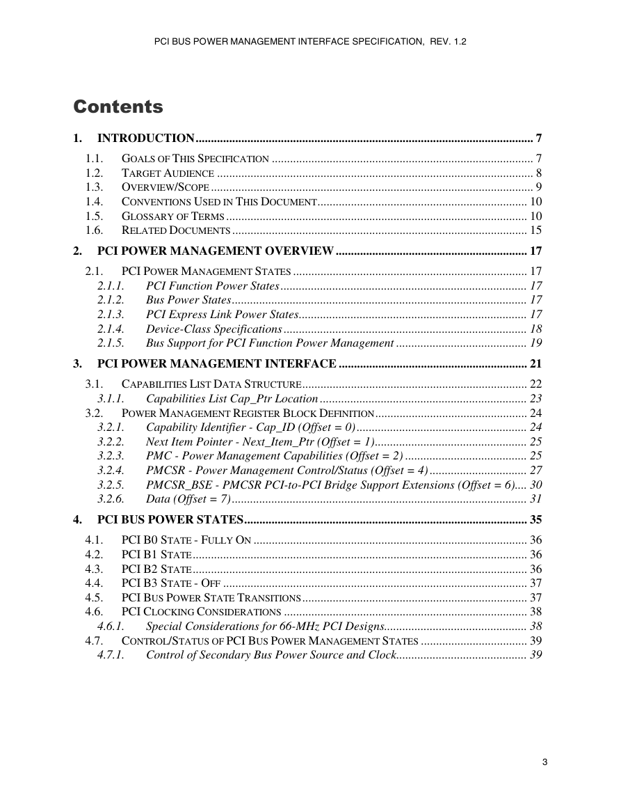
Contents
1. Introduction
1.1. Goals of This Specification
1.2. Target Audience
1.3. Overview/Scope
1.4. Conventions Used in This Document
1.5. Glossary of Terms
1.6. Related Documents
2. PCI Power Management Overview
2.1. PCI Power Management States
2.1.1. PCI Function Power States
2.1.2. Bus Power States
2.1.3. PCI Express Link Power States
2.1.4. Device-Class Specifications
2.1.5. Bus Support for PCI Function Power Management
3. PCI Power Management Interface
3.1. Capabilities List Data Structure
3.1.1. Capabilities List Cap_Ptr Location
3.2. Power Management Register Block Definition
3.2.1. Capability Identifier - Cap_ID (Offset = 0)
3.2.2. Next Item Pointer - Next_Item_Ptr (Offset = 1)
3.2.3. PMC - Power Management Capabilities (Offset = 2)
3.2.4. PMCSR - Power Management Control/Status (Offset = 4)
3.2.5. PMCSR_BSE - PMCSR PCI-to-PCI Bridge Support Extensions (Offset = 6)
3.2.6. Data (Offset = 7)
4. PCI Bus Power States
4.1. PCI B0 State - Fully On
4.2. PCI B1 State
4.3. PCI B2 State
4.4. PCI B3 State - Off
4.5. PCI Bus Power State Transitions
4.6. PCI Clocking Considerations
4.6.1. Special Considerations for 66-MHz PCI Designs
4.7. Control/Status of PCI Bus Power Management States
4.7.1. Control of Secondary Bus Power Source and Clock
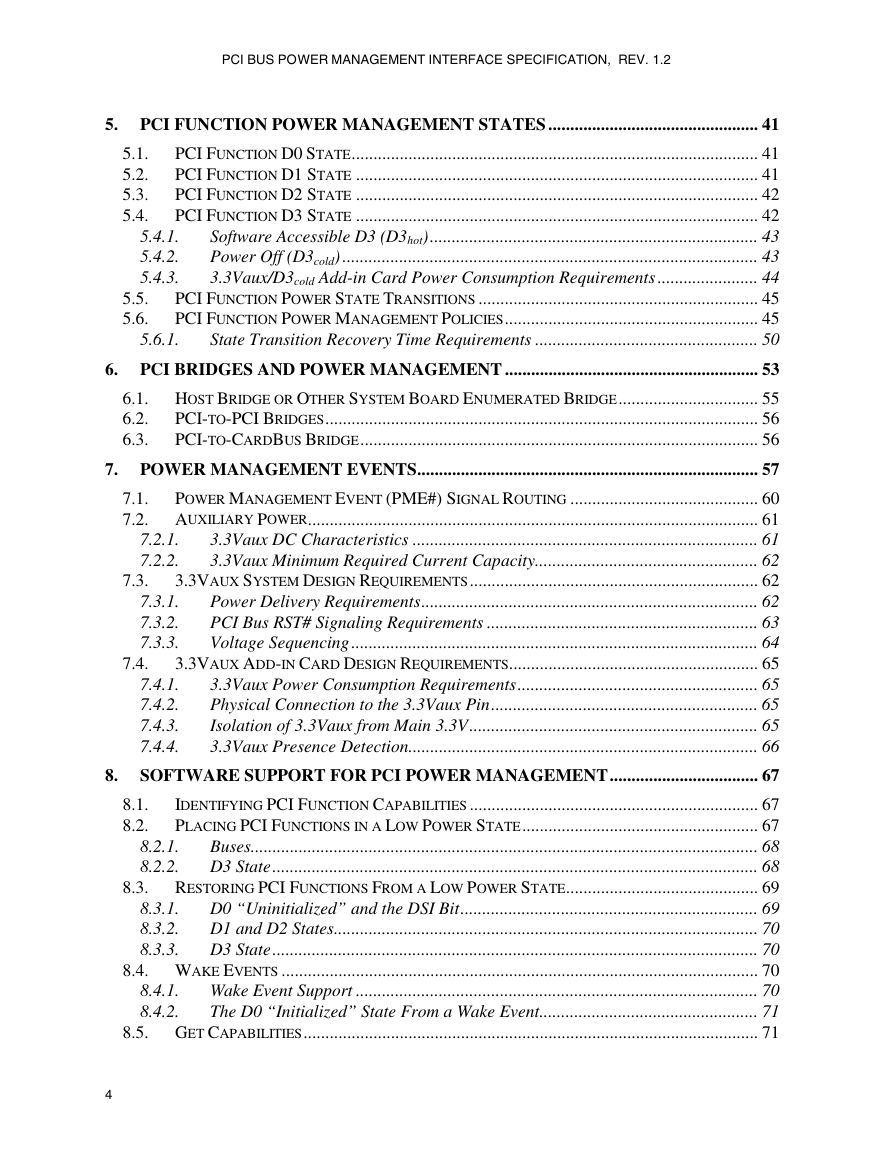
5. PCI Function Power Management States
5.1. PCI Function D0 State
5.2. PCI Function D1 State
5.3. PCI Function D2 State
5.4. PCI Function D3 State
5.4.1. Software Accessible D3 (D3hot)
5.4.2. Power Off (D3cold)
5.4.3. 3.3Vaux/D3cold Add-in Card Power Consumption Requirements
5.5. PCI Function Power State Transitions
5.6. PCI Function Power Management Policies
5.6.1. State Transition Recovery Time Requirements
6. PCI Bridges and Power Management
6.1. Host Bridge or Other System Board Enumerated Bridge
6.2. PCI-to-PCI Bridges
6.3. PCI-to-CardBus Bridge
7. Power Management Events
7.1. Power Management Event (PME#) Signal Routing
7.2. Auxiliary Power
7.2.1. 3.3Vaux DC Characteristics
7.2.2. 3.3Vaux Minimum Required Current Capacity
7.3. 3.3Vaux System Design Requirements
7.3.1. Power Delivery Requirements
7.3.2. PCI Bus RST# Signaling Requirements
7.3.3. Voltage Sequencing
7.4. 3.3Vaux Add-in Card Design Requirements
7.4.1. 3.3Vaux Power Consumption Requirements
7.4.2. Physical Connection to the 3.3Vaux Pin
7.4.3. Isolation of 3.3Vaux from Main 3.3V
7.4.4. 3.3Vaux Presence Detection
8. Software Support for PCI Power Management
8.1. Identifying PCI Function Capabilities
8.2. Placing PCI Functions in a Low Power State
8.2.1. Buses
8.2.2. D3 State
8.3. Restoring PCI Functions From a Low Power State
8.3.1. D0 “Uninitialized” and the DSI Bit
8.3.2. D1 and D2 States
8.3.3. D3 State
8.4. Wake Events
8.4.1. Wake Event Support
8.4.2. The D0 “Initialized” State From a Wake Event
8.5. Get Capabilities
8.6. Set Power State
8.7. Get Power Status
8.8. System Firmware Initialization
9. Other Considerations




 2023年江西萍乡中考道德与法治真题及答案.doc
 2012年重庆南川中考生物真题及答案.doc
 2013年江西师范大学地理学综合及文艺理论基础考研真题.doc
 2020年四川甘孜小升初语文真题及答案I卷.doc
 2020年注册岩土工程师专业基础考试真题及答案.doc
 2023-2024学年福建省厦门市九年级上学期数学月考试题及答案.doc
 2021-2022学年辽宁省沈阳市大东区九年级上学期语文期末试题及答案.doc
 2022-2023学年北京东城区初三第一学期物理期末试卷及答案.doc
 2018上半年江西教师资格初中地理学科知识与教学能力真题及答案.doc
 2012年河北国家公务员申论考试真题及答案-省级.doc
 2020-2021学年江苏省扬州市江都区邵樊片九年级上学期数学第一次质量检测试题及答案.doc
 2022下半年黑龙江教师资格证中学综合素质真题及答案.doc