NI-XNET Hardware and Software Manual
Support
Worldwide Technical Support and Product Information
Worldwide Offices
National Instruments Corporate Headquarters
Legal Information
Limited Warranty
Copyright
End-User License Agreements and Third-Party Legal Notices
U.S. Government Restricted Rights
Trademarks
Patents
Export Compliance Information
WARNING REGARDING USE OF NATIONAL INSTRUMENTS PRODUCTS
Compliance
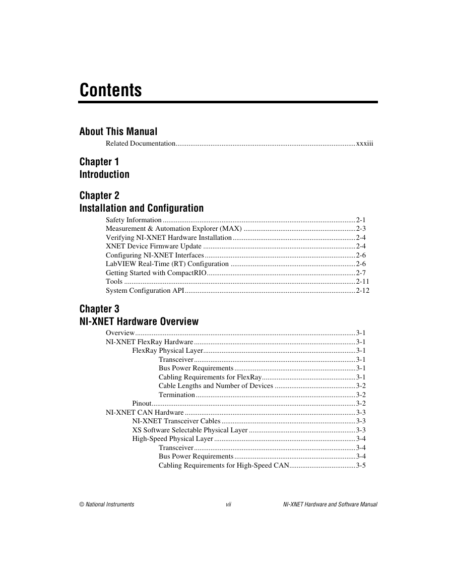
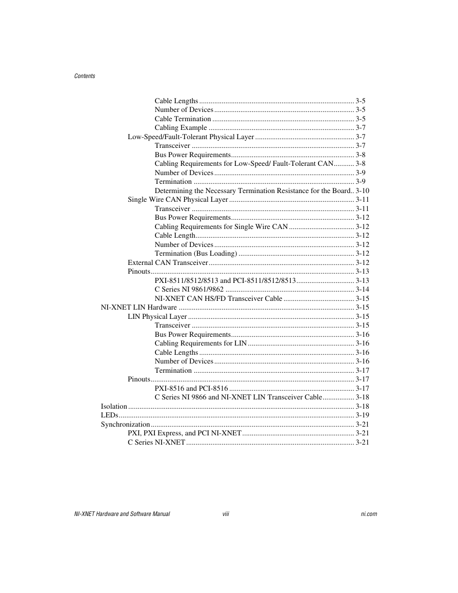
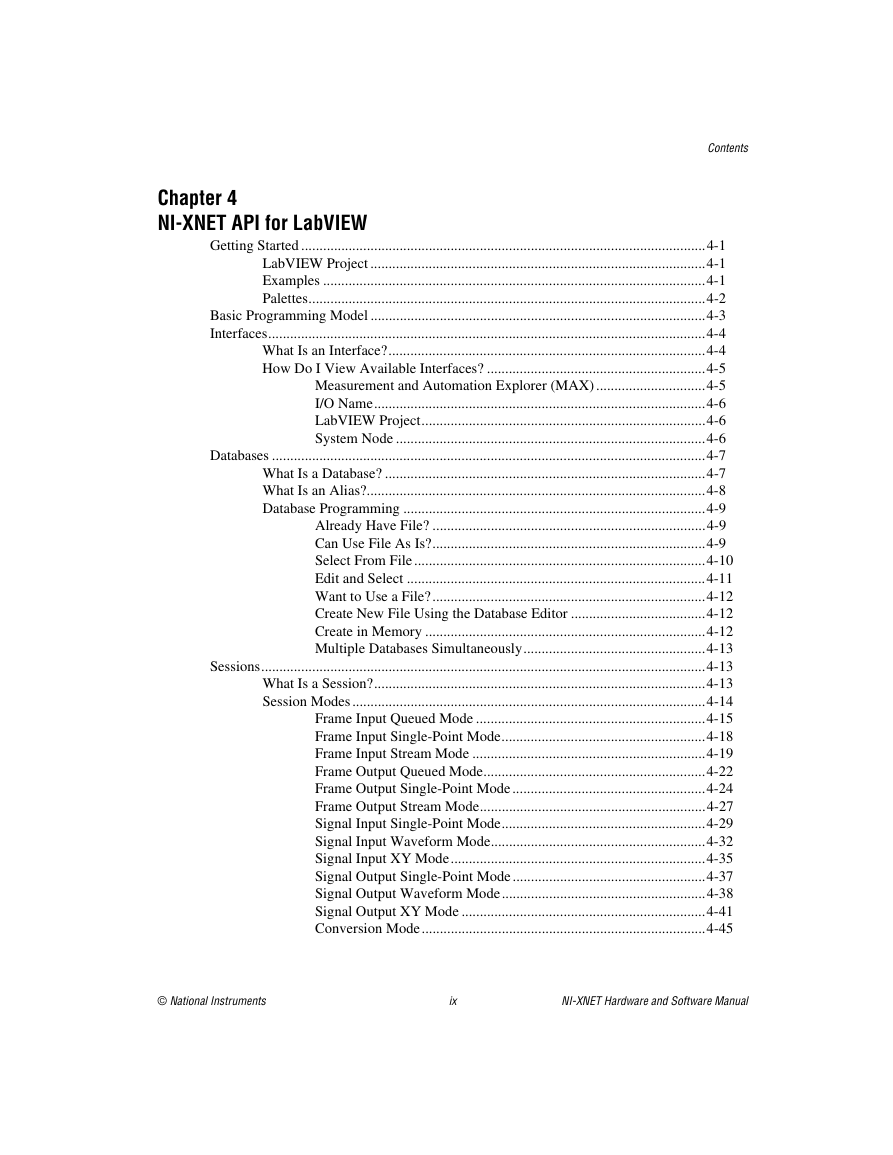
Contents
About This Manual
Related Documentation
Chapter 1 Introduction
Chapter 2 Installation and Configuration
Safety Information
Measurement & Automation Explorer (MAX)
Verifying NI-XNET Hardware Installation
Figure 2-1. NI-XNET Hardware Listed in MAX
XNET Device Firmware Update
Figure 2-2. XNET Firmware Mismatch
Configuring NI-XNET Interfaces
Figure 2-3. Renaming an Interface
LabVIEW Real-Time (RT) Configuration
Getting Started with CompactRIO
Table 2-1. Actions That Cause NI-XNET to Load
Table 2-2. Actions That Cause NI-XNET to Unload
Tools
System Configuration API
Chapter 3 NI-XNET Hardware Overview
Overview
NI-XNET FlexRay Hardware
FlexRay Physical Layer
Transceiver
Bus Power Requirements
Cabling Requirements for FlexRay
Table 3-1. FlexRay Cable Characteristics
Cable Lengths and Number of Devices
Termination
Pinout
Table 3-2. FlexRay DB9 Pinout
NI-XNET CAN Hardware
NI-XNET Transceiver Cables
XS Software Selectable Physical Layer
High-Speed Physical Layer
Transceiver
Bus Power Requirements
Cabling Requirements for High-Speed CAN
Table 3-3. ISO 11898 Specifications for Characteristics of a CAN_H and CAN_L Pair of Wires
Cable Lengths
Number of Devices
Cable Termination
Figure 3-1. Termination Resistor Placement
Cabling Example
Figure 3-2. Cable Connecting Two CAN Devices
Low-Speed/Fault-Tolerant Physical Layer
Transceiver
Bus Power Requirements
Cabling Requirements for Low-Speed/ Fault-Tolerant CAN
Table 3-4. Specifications for Characteristics of a CAN_H and CAN_L Pair of Wires
Number of Devices
Termination
Figure 3-3. Termination Resistor Placement for Low-Speed CAN
Determining the Necessary Termination Resistance for the Board
Single Wire CAN Physical Layer
Transceiver
Bus Power Requirements
Cabling Requirements for Single Wire CAN
Cable Length
Number of Devices
Termination (Bus Loading)
External CAN Transceiver
Pinouts
PXI-8511/8512/8513 and PCI-8511/8512/8513
Table 3-5. PXI and PCI NI-XNET CAN DB-9 Pinout
Table 3-6. PXI and PCI NI-XNET External CAN Transceiver DB-9 Pinout
C Series NI 9861/9862
Table 3-7. C Series NI-XNET CAN DB-9 Pinout
NI-XNET CAN HS/FD Transceiver Cable
Table 3-8. NI-XNET HS/FD Transceiver Cable DB-9 Pinout
NI-XNET LIN Hardware
LIN Physical Layer
Transceiver
Bus Power Requirements
Table 3-9. NI-XNET LIN Hardware Bus Power Requirements
Cabling Requirements for LIN
Cable Lengths
Number of Devices
Termination
Pinouts
PXI-8516 and PCI-8516
Table 3-10. PXI and PCI NI-XNET LIN DB-9 Pinout
C Series NI 9866 and NI-XNET LIN Transceiver Cable
Table 3-11. C Series NI-XNET LIN DB-9 Pinout
Isolation
LEDs
Synchronization
PXI, PXI Express, and PCI NI-XNET
C Series NI-XNET
Chapter 4 NI-XNET API for LabVIEW
Getting Started
LabVIEW Project
Examples
Palettes
Basic Programming Model
Interfaces
What Is an Interface?
How Do I View Available Interfaces?
Measurement and Automation Explorer (MAX)
I/O Name
LabVIEW Project
System Node
Databases
What Is a Database?
What Is an Alias?
Database Programming
Already Have File?
Can Use File As Is?
Select From File
LabVIEW Project
I/O Names
Property Nodes
Edit and Select
Edit in Memory
Edit the File
Want to Use a File?
Create New File Using the Database Editor
Create in Memory
Multiple Databases Simultaneously
Sessions
What Is a Session?
Session Modes
Frame Input Queued Mode
Example
Frame Input Single-Point Mode
Example
Frame Input Stream Mode
Example
Frame Output Queued Mode
Examples
Frame Output Single-Point Mode
Example
Frame Output Stream Mode
Example
Signal Input Single-Point Mode
Example
Signal Input Waveform Mode
Example
Signal Input XY Mode
Example
Signal Output Single-Point Mode
Example
Signal Output Waveform Mode
Example
Signal Output XY Mode
Examples
Conversion Mode
Example 1: Conversion of CAN Frames to Signals
Example 2: Conversion of Signals to FlexRay Frames
How Do I Create a Session?
LabVIEW Project
XNET Create Session.vi
Using CAN
CAN FD, ISO Versus Non-ISO
Understanding CAN Frame Timing
Configuring Frame I/O Stream Sessions
Using FlexRay
Starting Communication
Understanding FlexRay Frame Timing
Protocol Data Unit (PDU)
Using LIN
Changing the LIN Schedule
Understanding LIN Frame Timing
LIN Diagnostics
Special Considerations for Using Stream Output Mode with LIN
Using LabVIEW Real-Time
High Priority Loops
XNET I/O Names
Deploying Databases
Memory Use for Databases
FlexRay Timing Source
Creating a Built Real-Time Application
J1939 Sessions
Compatibility Issue
J1939 Basics
Node Addresses in NI-XNET
Address Claiming Procedure
Transmitting Frames
Transmitting Frames without Granted Node Address
Mixing J1939 and CAN Messages
Transport Protocol (TP)
NI-XNET Sessions
Not Supported in the Current NI-XNET Version
Signal Ranges
NI-XNET API for LabVIEW Reference
XNET Session Constant
XNET Create Session.vi
XNET Create Session (Conversion).vi
XNET Create Session (Frame Input Queued).vi
XNET Create Session (Frame Input Single-Point).vi
XNET Create Session (Frame Input Stream).vi
XNET Create Session (PDU Input Queued).vi
XNET Create Session (PDU Input Single Point).vi
XNET Create Session (Frame Output Queued).vi
XNET Create Session (Frame Output Single-Point).vi
XNET Create Session (Frame Output Stream).vi
XNET Create Session (PDU Output Queued).vi
XNET Create Session (PDU Output Single-Point).vi
XNET Create Session (Generic).vi
XNET Create Session (Signal Input Single-Point).vi
XNET Create Session (Signal Input Waveform).vi
XNET Create Session (Signal Input XY).vi
XNET Create Session (Signal Output Single-Point).vi
XNET Create Session (Signal Output Waveform).vi
XNET Create Session (Signal Output XY).vi
XNET Session Property Node
Interface Properties
CAN Interface Properties
Interface:CAN:64bit FD Baud Rate
Interface:CAN:Disable Protocol Exception Handling
Interface:CAN:Enable Edge Filter
Interface:CAN:External Transceiver Config
Interface:CAN:FD ISO Mode
Interface:CAN:I/O Mode
Interface:CAN:Listen Only?
Interface:CAN:Pending Transmit Order
Interface:CAN:Single Shot Transmit?
Interface:CAN:Termination
Interface:CAN:Transceiver State
Interface:CAN:Transceiver Type
Interface:CAN:Transmit I/O Mode
Interface:CAN:Transmit Pause
FlexRay Interface Properties
Interface:FlexRay:Accepted Startup Range
Interface:FlexRay:Allow Halt Due To Clock?
Interface:FlexRay:Allow Passive to Active
Interface:FlexRay:Auto Asleep When Stopped
Interface:FlexRay:Cluster Drift Damping
Interface:FlexRay:Coldstart?
Interface:FlexRay:Connected Channels
Interface:FlexRay:Decoding Correction
Interface:FlexRay:Delay Compensation Ch A
Interface:FlexRay:Delay Compensation Ch B
Interface:FlexRay:Key Slot Identifier
Interface:FlexRay:Latest Tx
Interface:FlexRay:Listen Timeout
Interface:FlexRay:Macro Initial Offset Ch A
Interface:FlexRay:Macro Initial Offset Ch B
Interface:FlexRay:Max Drift
Interface:FlexRay:Micro Initial Offset Ch A
Interface:FlexRay:Micro Initial Offset Ch B
Interface:FlexRay:Microtick
Interface:FlexRay:Null Frames To Input Stream?
Interface:FlexRay:Offset Correction
Interface:FlexRay:Offset Correction Out
Interface:FlexRay:Rate Correction
Interface:FlexRay:Rate Correction Out
Interface:FlexRay:Samples Per Microtick
Interface:FlexRay:Single Slot Enabled?
Interface:FlexRay:Sleep
Interface:FlexRay:Statistics Enabled?
Interface:FlexRay:Symbol Frames To Input Stream?
Interface:FlexRay:Sync Frames Channel A Even
Interface:FlexRay:Sync Frames Channel A Odd
Interface:FlexRay:Sync Frames Channel B Even
Interface:FlexRay:Sync Frames Channel B Odd
Interface:FlexRay:Sync Frame Status
Interface:FlexRay:Termination
Interface:FlexRay:Wakeup Channel
Interface:FlexRay:Wakeup Pattern
LIN Interface Properties
Interface:LIN:Break Length
Interface:LIN:DiagP2min
Interface:LIN:DiagSTmin
Interface:LIN:Master?
Interface:LIN:Output Stream Slave Response List By NAD
Interface:LIN:Schedules
Interface:LIN:Sleep
Table 4-1. Sleep/Wake Action for Master
Table 4-2. Sleep/Wake Action for Slave
Interface:LIN:Start Allowed without Bus Power?
Interface:LIN:Termination
Source Terminal Interface Properties
Interface:Source Terminal:Start Trigger
Interface:64bit Baud Rate
Interface:Echo Transmit?
Interface:I/O Name
Interface:Output Stream List
Interface:Output Stream List By ID
Interface:Output Stream Timing
Interface:Start Trigger Frames to Input Stream?
Interface:Bus Error Frames to Input Stream?
Session:Application Protocol
SAE J1939:ECU
SAE J1939:ECU Busy
SAE J1939:Hold Time Th
SAE J1939:Maximum Repeat CTS
SAE J1939:Node Address
SAE J1939:NodeName
SAE J1939:Number of Packets Received
SAE J1939:Number of Packets Response
SAE J1939:Response Time Tr_GD
SAE J1939:Response Time Tr_SD
SAE J1939:Timeout T1
SAE J1939:Timeout T2
SAE J1939:Timeout T3
SAE J1939:Timeout T4
Frame Properties
CAN Frame Properties
Frame:CAN:Start Time Offset
Frame:CAN:Transmit Time
Frame:Active
Frame:LIN:Transmit N Corrupted Checksums
Frame:Skip N Cyclic Frames
Auto Start?
Cluster
Database
List of Frames
List of Signals
Mode
Number in List
Number of Values Pending
Number of Values Unused
Payload Length Maximum
Protocol
Queue Size
Resample Rate
XNET Read.vi
XNET Read (Frame CAN).vi
XNET Read (Frame FlexRay).vi
XNET Read (Frame LIN).vi
XNET Read (Frame Raw).vi
XNET Read (Signal Single-Point).vi
XNET Read (Signal Waveform).vi
XNET Read (Signal XY).vi
XNET Read (State CAN Comm).vi
XNET Read (State FlexRay Comm).vi
XNET Read (State LIN Comm).vi
XNET Read (State SAE J1939 Comm).vi
XNET Read (State FlexRay Cycle Macrotick).vi
XNET Read (State FlexRay Statistics).vi
XNET Read (State Time Comm).vi
XNET Read (State Time Current).vi
XNET Read (State Time Start).vi
XNET Read (State Session Info).vi
XNET Write.vi
XNET Write (Signal Single-Point).vi
XNET Write (Signal Waveform).vi
XNET Write (Signal XY).vi
XNET Write (Frame CAN).vi
XNET Write (Frame FlexRay).vi
XNET Write (Frame LIN).vi
XNET Write (Frame Raw).vi
XNET Write (State FlexRay Symbol).vi
XNET Write (State LIN Schedule Change).vi
XNET Write (State LIN Diagnostic Schedule Change).vi
Database Subpalette
XNET Database Property Node
Clusters
ShowInvalidFromOpen?
XNET Database Constant
XNET Cluster Property Node
FlexRay Properties
FlexRay:Action Point Offset
FlexRay:CAS Rx Low Max
FlexRay:Channels
FlexRay:Cluster Drift Damping
FlexRay:Cold Start Attempts
FlexRay:Cycle
FlexRay:Dynamic Segment Start
FlexRay:Dynamic Slot Idle Phase
FlexRay:Latest Guaranteed Dynamic Slot
FlexRay:Latest Usable Dynamic Slot
FlexRay:Listen Noise
FlexRay:Macro Per Cycle
FlexRay:Macrotick
FlexRay:Max Without Clock Correction Fatal
FlexRay:Max Without Clock Correction Passive
FlexRay:Minislot Action Point Offset
FlexRay:Minislot
FlexRay:Network Management Vector Length
FlexRay:NIT Start
FlexRay:NIT
FlexRay:Number of Minislots
FlexRay:Number of Static Slots
FlexRay:Offset Correction Start
FlexRay:Payload Length Dynamic Maximum
FlexRay:Payload Length Maximum
FlexRay:Payload Length Static
FlexRay:Static Slot
FlexRay:Symbol Window Start
FlexRay:Symbol Window
FlexRay:Sync Node Max
FlexRay:TSS Transmitter
FlexRay:Use Wakeup
FlexRay:Wakeup Symbol Rx Idle
FlexRay:Wakeup Symbol Rx Low
FlexRay:Wakeup Symbol Rx Window
FlexRay:Wakeup Symbol Tx Idle
FlexRay:Wakeup Symbol Tx Low
64bit Baud Rate
Application Protocol
CAN:64bit FD Baud Rate
CAN:FD ISO Mode
CAN:I/O Mode
Comment
Configuration Status
Database
ECUs
Frames
LIN:Schedules
LIN:Tick
Name (Short)
PDUs
PDUs Required?
Protocol
Signals
XNET Cluster Constant
XNET ECU Property Node
Cluster
FlexRay:Coldstart?
FlexRay:Connected Channels
FlexRay:Startup Frame
FlexRay:Wakeup Channels
FlexRay:Wakeup Pattern
Comment
Configuration Status
Frames Received
Frames Transmitted
LIN:Master?
LIN:Protocol Version
LIN:Initial NAD
LIN:Configured NAD
LIN:Supplier ID
LIN:Function ID
LIN:P2min
LIN:STmin
Name (Short)
XNET ECU Constant
XNET Frame Property Node
CAN:Extended Identifier?
CAN:I/O Mode
CAN:Timing Type
CAN:Transmit Time
Application Protocol
Cluster
Comment
Configuration Status
Default Payload
FlexRay:Base Cycle
FlexRay:Channel Assignment
FlexRay:Cycle Repetition
FlexRay:Payload Preamble?
FlexRay:Startup?
FlexRay:Sync?
FlexRay:Timing Type
FlexRay:In Cycle Repetitions:Channel Assignments
FlexRay:In Cycle Repetitions:Enabled?
FlexRay:In Cycle Repetitions:Identifiers
Identifier
LIN:Checksum
Mux:Data Multiplexer Signal
Mux:Is Data Multiplexed?
Mux:Static Signals
Mux:Subframes
Name (Short)
Payload Length
PDU_Mapping
Signals
XNET Frame Constant
XNET PDU Property Node
Cluster
Comment
Configuration Status
Frames
Mux:Data Multiplexer Signal
Mux:Is Data Multiplexed?
Mux:Static Signals
Mux:Subframes
Name (Short)
Payload Length
Signals
XNET PDU Constant
XNET Subframe Property Node
Dynamic Signals
Frame
Multiplexer Value
Name (Short)
PDU
XNET Signal Property Node
Byte Order
Comment
Configuration Status
Data Type
Default Value
Mux:Dynamic?
Frame
Maximum Value
Minimum Value
Mux:Multiplexer Value
Mux:Data Multiplexer?
Name (Short)
Number of Bits
PDU
Scaling Factor
Scaling Offset
Start Bit
Mux:Subframe
Unit
XNET Signal Constant
XNET Database Open.vi
XNET Database Close.vi
XNET Database Close (Cluster).vi
XNET Database Close (Database).vi
XNET Database Close (ECU).vi
XNET Database Close (Frame).vi
XNET Database Close (PDU).vi
XNET Database Close (Signal).vi
XNET Database Close (Subframe).vi
XNET Database Close (LIN Schedule).vi
XNET Database Close (LIN Schedule Entry).vi
XNET Database Create Object.vi
XNET Database Create (Cluster).vi
XNET Database Create (Dynamic Signal).vi
XNET Database Create (ECU).vi
XNET Database Create (Frame).vi
XNET Database Create (PDU).vi
XNET Database Create (Signal).vi
XNET Database Create (Subframe).vi
XNET Database Create (LIN Schedule).vi
XNET Database Create (LIN Schedule Entry).vi
XNET Database Delete Object.vi
XNET Database Delete (Cluster).vi
XNET Database Delete (ECU).vi
XNET Database Delete (Frame).vi
XNET Database Delete (PDU).vi
XNET Database Delete (Signal).vi
XNET Database Delete (Subframe).vi
XNET Database Delete (LIN Schedule).vi
XNET Database Delete (LIN Schedule Entry).vi
XNET Database Merge.vi
XNET Database Merge (Frame).vi
XNET Database Merge (PDU).vi
XNET Database Merge (ECU).vi
XNET Database Merge (LIN Schedule).vi
XNET Database Merge (Cluster).vi
XNET Database Save.vi
XNET Database Export.vi
File Management Subpalette
XNET Database Add Alias.vi
XNET Database Remove Alias.vi
XNET Database Get List.vi
XNET Database Deploy.vi
XNET Database Undeploy.vi
XNET LIN Schedule Property Node
Cluster
Comment
Configuration Status
Entries
Name (Short)
Priority
Run Mode
XNET LIN Schedule Entry Property Node
Collision Resolving Schedule
Delay
Event Identifier
Frames
Name (Short)
Node Configuration:Free Format:Data Bytes
Schedule
Type
XNET Database Get DBC Attribute.vi
Notify Subpalette
XNET Wait.vi
XNET Wait (Transmit Complete).vi
XNET Wait (Interface Communicating).vi
XNET Wait (CAN Remote Wakeup).vi
XNET Wait (LIN Remote Wakeup).vi
XNET Create Timing Source.vi
XNET Create Timing Source (FlexRay Cycle).vi
Advanced Subpalette
XNET Start.vi
XNET Stop.vi
XNET Clear.vi
XNET Flush.vi
XNET Connect Terminals.vi
XNET Disconnect Terminals.vi
XNET Terminal Constant
XNET System Property Node
Devices
Interfaces (FlexRay)
Interfaces (All)
Interfaces (CAN)
Interfaces (LIN)
Version:Build
Version:Major
Version:Minor
Version:Phase
Version:Update
XNET Device Property Node
Form Factor
Interfaces
Number of Ports
Product Name
Product Number
Serial Number
Slot Number
XNET Interface Property Node
CAN.Termination Capability
CAN.Transceiver Capability
Device
Name
Number
Port Number
Protocol
XNET Interface Constant
XNET Blink.vi
XNET System Close.vi
XNET String to IO Name.vi
XNET Convert.vi
XNET Convert (Frame CAN to Signal).vi
XNET Convert (Frame FlexRay to Signal).vi
XNET Convert (Frame LIN to Signal).vi
XNET Convert (Frame Raw to Signal).vi
XNET Convert (Signal to Frame CAN).vi
XNET Convert (Signal to Frame FlexRay).vi
XNET Convert (Signal to Frame LIN).vi
XNET Convert (Signal to Frame Raw).vi
Controls Palette
XNET Session Control
Database Controls
System Controls
Additional Topics
Overall
Creating a Built Application
Sessions
Databases
Cyclic and Event Timing
CAN
FlexRay
LIN
Error Handling
Fault Handling
Multiplexed Signals
Creating Multiplexed Signals
In the API
In the NI-XNET Database Editor
Reading Multiplexed Signals
Writing Multiplexed Signals
Support for Multiplexed Signals
Raw Frame Format
Base Unit
Table 4-3. Base Unit Elements
Payload Unit
Table 4-4. Payload Unit Elements
Special Frames
Delay Frame
Log Trigger Frame
CAN Frame
LIN Frame
FlexRay Frame
Start Trigger Frame
CAN Frame
LIN Frame
FlexRay Frame
Bus Error Frame
CAN Frame
LIN Frame
Required Properties
State Models
Session State Model
Interface State Model
Session States
Stopped
Started
Communicating
Session Transitions
Create
Clear
Set Session Property
Start Session
Stop Session
Interface Communicating
Interface Not Communicating
Interface States
Stopped
Started
Communicating
Interface Transitions
Set Interface Property
Start Interface
Stop Interface
Comm State Communicating
Comm State Not Communicating
TDMS
Channel Name and Group Name
Channel Data
Channel Properties
Table 4-5. Channel Properties
CAN
NI-CAN
Compatibility
NI-XNET CAN Products in MAX
Transition
Table 4-6. NI-CAN and NI-XNET Terms
CAN Timing Type and Session Mode
Cyclic Data
Signal Input Single-Point, Signal Input Waveform, Signal Input XY, Frame Input Single-Point, and Frame Input Queued Modes
Frame Input Stream Mode
Signal Output Single-Point, Signal Output Waveform, Signal Output XY, Frame Output Single-Point, and Frame Output Queued Modes
Frame Output Stream Mode
Event Data
Signal Input Single-Point, Signal Input Waveform, Signal Input XY, Frame Input Single-Point, and Frame Input Queued Modes
Frame Input Stream Mode
Signal Output Single-Point, Signal Output Waveform, Signal Output XY, Frame Output Single-Point, and Frame Output Queued Modes
Frame Output Stream Mode
Cyclic Remote
Signal Input Single-Point, Signal Input Waveform, Signal Input XY, Frame Input Single-Point, and Frame Input Queued Modes
Frame Input Stream Mode
Signal Output Single-Point, Signal Output Waveform, Signal Output XY, Frame Output Single-Point, and Frame Output Queued Modes
Frame Output Stream Modes
Event Remote
Signal Input Single-Point, Signal Input Waveform, Signal Input XY, Frame Input Single-Point, and Frame Input Queued Modes
Frame Input Stream Modes
Signal Output Single-Point, Signal Output Waveform, Signal Output XY, Frame Output Single-Point, and Frame Output Queued Modes
Frame Output Stream Mode
CAN Transceiver State Machine
FlexRay
FlexRay Timing Type and Session Mode
Cyclic Data
Signal Input Single-Point, Signal Input Waveform, and Signal Input XY Modes
Frame Input Queued and Frame Input Single-Point Modes
Frame Input Stream Mode
Signal Output Single-Point, Signal Output Waveform, Signal Output XY, Frame Output Single-Point, and Frame Output Queued Modes
Frame Output Stream Mode
Event Data
Signal Input Single-Point, Signal Input Waveform, Signal Input XY, Frame Input Single-Point, Frame Input Queued, and Frame Input Stream Modes
Signal Output Single-Point, Signal Output Waveform, Signal Output XY, Frame Output Single-Point, and Frame Output Queued Modes
Frame Output Stream Mode
Protocol Data Units (PDUs) in NI-XNET
Introduction to Protocol Data Units
Relationship Between Frames, Signals, and PDUs
Protocol Data Unit Properties
Start Bit
Length
Update Bit
PDU Timing and Frame Timing
Programming PDUs with NI-XNET
FlexRay Startup/Wakeup
LIN
LIN Frame Timing and Session Mode
Cyclic
Signal Input Single-Point, Signal Input Waveform, and Signal Input XY Modes
Frame Input Queued and Frame Input Single-Point Modes
Frame Input Stream Mode
Signal Output Single-Point, Signal Output XY, Frame Output Single-Point, and Frame Output Queued Modes
Signal Output Waveform Mode
Frame Output Stream Mode
Event
Signal Input Single-Point, Signal Input Waveform, Signal Input XY, Frame Input Single-Point, Frame Input Queued, and Frame Input Stream Modes
Signal Output Single-Point, Signal Output XY, Frame Output Single-Point, and Frame Output Queued Modes
Signal Output Waveform Mode
Frame Output Stream Mode
XNET I/O Names
I/O Name Classes
Session
Database Classes
System Classes
XNET Cluster I/O Name
User Interface
String Use
Refnum Use
XNET Database I/O Name
User Interface
String Use
Refnum Use
XNET Device I/O Name
User Interface
String Use
Refnum Use
XNET ECU I/O Name
User Interface
String Use
Refnum Use
XNET Frame I/O Name
User Interface
String Use
Refnum Use
XNET Interface I/O Name
User Interface
String Use
Refnum Use
XNET Session I/O Name
User Interface
String Use
Refnum Use
XNET Signal I/O Name
User Interface
String Use
Refnum Use
XNET Subframe I/O Name
User Interface
String Use
Refnum Use
XNET Terminal I/O Name
User Interface
String Use
Refnum Use
XNET LIN Schedule I/O Name
User Interface
String Use
Refnum Use
XNET LIN Schedule Entry I/O Name
User Interface
String Use
Refnum Use
XNET PDU I/O Name
User Interface
String Use
Refnum Use
Chapter 5 NI-XNET API for C
Getting Started
LabWindows/CVI
Examples
Visual C++
Examples
Interfaces
What Is an Interface?
How Do I View Available Interfaces?
Measurement and Automation Explorer (MAX)
Databases
What Is a Database?
What Is an Alias?
Database Programming
Already Have File?
Can I Use File as Is?
Select From File
Edit and Select
Edit in Memory
Edit the File
Want to Use a File?
Create New File Using the Database Editor
Create in Memory
Sessions
What Is a Session?
Session Modes
Frame Input Queued Mode
Example
Frame Input Single-Point Mode
Example
Frame Input Stream Mode
Example
Frame Output Queued Mode
Examples
Frame Output Single-Point Mode
Example
Frame Output Stream Mode
Example
Signal Input Single-Point Mode
Example
Signal Input Waveform Mode
Example
Signal Input XY Mode
Example
Signal Output Single-Point Mode
Example
Signal Output Waveform Mode
Example
Signal Output XY Mode
Examples
Conversion Mode
Example 1: Conversion of CAN Frames to Signals
Example 2: Conversion of Signals to FlexRay Frames
J1939 Sessions
Compatibility Issue
J1939 Basics
Node Addresses in NI-XNET
Address Claiming Procedure
Transmitting Frames
Transmitting Frames without Granted Node Address
Mixing J1939 and CAN Messages
Transport Protocol (TP)
NI-XNET Sessions
Not Supported in the Current NI-XNET Version
Signal Ranges
CAN FD, ISO Versus Non-ISO
NI-XNET API for C Reference
Functions
nxBlink
nxClear
nxConnectTerminals
nxConvertFramesToSignalsSinglePoint
nxConvertSignalsToFramesSinglePoint
nxCreateSession
nxCreateSessionByRef
nxdbAddAlias
nxdbAddAlias64
nxdbCloseDatabase
nxdbCreateObject
nxdbDeleteObject
nxdbDeploy
nxdbFindObject
nxdbGetDatabaseList
nxdbGetDatabaseListSizes
nxdbGetDBCAttribute
nxdbGetDBCAttributeSize
nxdbGetProperty
nxdbGetPropertySize
nxdbMerge
nxdbOpenDatabase
nxdbRemoveAlias
nxdbSaveDatabase
nxdbSetProperty
nxdbUndeploy
nxDisconnectTerminals
nxFlush
nxGetProperty
nxGetPropertySize
nxGetSubProperty
nxGetSubPropertySize
nxReadFrame
nxReadSignalSinglePoint
nxReadSignalWaveform
nxReadSignalXY
nxReadState
nxSetProperty
nxSetSubProperty
nxStart
nxStatusToString
nxStop
nxSystemClose
nxSystemOpen
nxWait
nxWriteFrame
nxWriteSignalSinglePoint
nxWriteSignalWaveform
nxWriteSignalXY
nxWriteState
Properties
XNET Cluster Properties
64bit Baud Rate
Application Protocol
CAN:64bit FD Baud Rate
CAN:FD ISO Mode
CAN:I/O Mode
Comment
Configuration Status
Database
ECUs
FlexRay:Action Point Offset
FlexRay:CAS Rx Low Max
FlexRay:Channels
FlexRay:Cluster Drift Damping
FlexRay:Cold Start Attempts
FlexRay:Cycle
FlexRay:Dynamic Segment Start
FlexRay:Dynamic Slot Idle Phase
FlexRay:Latest Guaranteed Dynamic Slot
FlexRay:Latest Usable Dynamic Slot
FlexRay:Listen Noise
FlexRay:Macro Per Cycle
FlexRay:Macrotick
FlexRay:Max Without Clock Correction Fatal
FlexRay:Max Without Clock Correction Passive
FlexRay:Minislot
FlexRay:Minislot Action Point Offset
FlexRay:Network Management Vector Length
FlexRay:NIT
FlexRay:NIT Start
FlexRay:Number of Minislots
FlexRay:Number of Static Slots
FlexRay:Offset Correction Start
FlexRay:Payload Length Dynamic Maximum
FlexRay:Payload Length Maximum
FlexRay:Payload Length Static
FlexRay:Static Slot
FlexRay:Symbol Window
FlexRay:Symbol Window Start
FlexRay:Sync Node Max
FlexRay:TSS Transmitter
FlexRay:Use Wakeup
FlexRay:Wakeup Symbol Rx Idle
FlexRay:Wakeup Symbol Rx Low
FlexRay:Wakeup Symbol Rx Window
FlexRay:Wakeup Symbol Tx Idle
FlexRay:Wakeup Symbol Tx Low
Frames
Name (Short)
PDUs
PDUs Required?
Protocol
Schedules
Signals
Tick
XNET Database Properties
Clusters
ShowInvalidFromOpen?
XNET Device Properties
Form Factor
Interfaces
Number of Ports
Product Name
Product Number
Serial Number
Slot Number
XNET ECU Properties
Cluster
Comment
Configuration Status
FlexRay:Coldstart?
FlexRay:Connected Channels
FlexRay:Startup Frame
FlexRay:Wakeup Channels
FlexRay:Wakeup Pattern
Frames Received
Frames Transmitted
LIN Master
LIN Version
LIN:Initial NAD
LIN:Configured NAD
LIN:Supplier ID
LIN:Function ID
LIN:P2min
LIN:STmin
Name (Short)
XNET Frame Properties
CAN:Extended Identifier?
CAN:I/O Mode
CAN:Timing Type
CAN:Transmit Time
Cluster
Comment
Configuration Status
Default Payload
FlexRay:Base Cycle
FlexRay:Channel Assignment
FlexRay:Cycle Repetition
FlexRay:In Cycle Repetitions:Channel Assignments
FlexRay:In Cycle Repetitions:Enabled?
FlexRay:In Cycle Repetitions:Identifiers
FlexRay:Payload Preamble?
FlexRay:Startup?
FlexRay:Sync?
FlexRay:Timing Type
Identifier
LIN:Checksum
Mux:Data Multiplexer Signal
Mux:Is Data Multiplexed?
Mux:Static Signals
Mux:Subframes
Name (Short)
Payload Length
PDU References
PDU Start Bits
PDU Update Bits
Signals
Application Protocol
XNET Interface Properties
CAN.Termination Capability
CAN.Transceiver Capability
Device
Name
Number
Port Number
Protocol
XNET LIN Schedule Properties
Cluster
Comment
Configuration Status
Entries
Name
Priority
Run Mode
XNET LIN Schedule Entry Properties
Collision Resolving Schedule
Delay
Event Identifier
Frames
Name
Name Unique to Cluster
Node Configuration:Free Format:Data Bytes
Schedule
Type
XNET PDU Properties
Cluster
Comment
Configuration Status
Frames
Mux:Data Multiplexer Signal
Mux:Is Data Multiplexed?
Mux:Static Signals
Mux:Subframes
Name (Short)
Payload Length
Signals
XNET Session Properties
Interface Properties
CAN Interface Properties
Interface:CAN:64bit FD Baud Rate
Interface:CAN:Disable Protocol Exception Handling
Interface:CAN:Enable Edge Filter
Interface:CAN:External Transceiver Config
Interface:CAN:FD ISO Mode
Interface:CAN:I/O Mode
Interface:CAN:Listen Only?
Interface:CAN:Pending Transmit Order
Interface:CAN:Single Shot Transmit?
Interface:CAN:Termination
Interface:CAN:Transceiver State
Interface:CAN:Transceiver Type
Interface:CAN:Transmit I/O Mode
Interface:CAN:Transmit Pause
FlexRay Interface Properties
Interface:FlexRay:Accepted Startup Range
Interface:FlexRay:Allow Halt Due To Clock?
Interface:FlexRay:Allow Passive to Active
Interface:FlexRay:AutoAsleepWhenStopped
Interface:FlexRay:Cluster Drift Damping
Interface:FlexRay:Coldstart?
Interface:FlexRay:Connected Channels
Interface:FlexRay:Decoding Correction
Interface:FlexRay:Delay Compensation Ch A
Interface:FlexRay:Delay Compensation Ch B
Interface:FlexRay:Key Slot Identifier
Interface:FlexRay:Latest Tx
Interface:FlexRay:Listen Timeout
Interface:FlexRay:Macro Initial Offset Ch A
Interface:FlexRay:Macro Initial Offset Ch B
Interface:FlexRay:Max Drift
Interface:FlexRay:Micro Initial Offset Ch A
Interface:FlexRay:Micro Initial Offset Ch B
Interface:FlexRay:Microtick
Interface:FlexRay:Null Frames To Input Stream?
Interface:FlexRay:Offset Correction
Interface:FlexRay:Offset Correction Out
Interface:FlexRay:Rate Correction
Interface:FlexRay:Rate Correction Out
Interface:FlexRay:Samples Per Microtick
Interface:FlexRay:Single Slot Enabled?
Interface:FlexRay:Sleep
Interface:FlexRay:Statistics Enabled?
Interface:FlexRay:Symbol Frames To Input Stream?
Interface:FlexRay:Sync Frame Status
Interface:FlexRay:Sync Frames Channel A Even
Interface:FlexRay:Sync Frames Channel A Odd
Interface:FlexRay:Sync Frames Channel B Even
Interface:FlexRay:Sync Frames Channel B Odd
Interface:FlexRay:Termination
Interface:FlexRay:Wakeup Channel
Interface:FlexRay:Wakeup Pattern
LIN Interface Properties
Interface:LIN:Break Length
Interface:LIN:DiagP2min
Interface:LIN:DiagSTmin
Interface:LIN:Master?
Interface:LIN:Output Stream Slave Response List By NAD
Interface:LIN:Schedule Names
Interface:LIN:Sleep
Table 5-1. Sleep/Wake Action for Master
Table 5-2. Sleep/Wake Action for Slave
Interface:LIN:Start Allowed without Bus Power?
Interface:LIN:Termination
Source Terminal Interface Properties
Interface:Source Terminal:Start Trigger
Interface:64bit Baud Rate
Interface:Echo Transmit?
Interface:Output Stream List
Interface:Output Stream List By ID
Interface:Output Stream Timing
Interface:Start Trigger Frames to Input Stream?
Interface:Bus Error Frames to Input Stream?
Session:Application Protocol
SAE J1939:ECU
SAE J1939:ECU Busy
SAE J1939:Hold Time Th
SAE J1939:Maximum Repeat CTS
SAE J1939:Node Address
SAE J1939:NodeName
SAE J1939:Number of Packets Received
SAE J1939:Number of Packets Response
SAE J1939:Response Time Tr_GD
SAE J1939:Response Time Tr_SD
SAE J1939:Timeout T1
SAE J1939:Timeout T2
SAE J1939:Timeout T3
SAE J1939:Timeout T4
Frame Properties
CAN Frame Properties
Frame:CAN:Start Time Offset
Frame:CAN:Transmit Time
Frame:LIN:Transmit N Corrupted Checksums
Frame:Skip N Cyclic Frames
Auto Start?
ClusterName
DatabaseName
List
Mode
Number in List
Number of Values Pending
Number of Values Unused
Payload Length Maximum
Protocol
Queue Size
Resample Rate
XNET Signal Properties
Byte Order
Comment
Configuration Status
Data Type
Default Value
Frame
Maximum Value
Minimum Value
Mux:Data Multiplexer?
Mux:Dynamic?
Mux:Multiplexer Value
Mux:Subframe
Name (Short)
Name Unique to Cluster
Number of Bits
PDU
Scaling Factor
Scaling Offset
Start Bit
Unit
XNET Subframe Properties
Dynamic Signals
Frame
Multiplexer Value
Name (Short)
Name Unique to Cluster
PDU
XNET System Properties
Devices
Interfaces (All)
Interfaces (CAN)
Interfaces (FlexRay)
Interfaces (LIN)
Version:Build
Version:Major
Version:Minor
Version:Phase
Version:Update
Additional Topics
Overall
Cyclic and Event Timing
CAN
FlexRay
LIN
Multiplexed Signals
Creating Multiplexed Signals
In the API
In the NI-XNET Database Editor
Reading Multiplexed Signals
Writing Multiplexed Signals
Support for Multiplexed Signals
Raw Frame Format
Base Unit
Table 5-3. Base Unit Elements
Payload Unit
Table 5-4. Payload Unit Elements
Special Frames
Delay Frame
Log Trigger Frame
Start Trigger Frame
Bus Error Frame
CAN Frame
LIN Frame
Required Properties
State Models
Session State Model
Interface State Model
Session States
Stopped
Started
Communicating
Session Transitions
Create
Clear
Set Session Property
Start Session
Stop Session
Interface Communicating
Interface Not Communicating
Interface States
Stopped
Started
Communicating
Interface Transitions
Set Interface Property
Start Interface
Stop Interface
Comm State Communicating
Comm State Not Communicating
CAN
NI-CAN
Compatibility
NI-XNET CAN Products in MAX
Transition
Table 5-5. NI-CAN and NI-XNET Terms
CAN Timing Type and Session Mode
Cyclic Data
Signal Input Single-Point, Signal Input Waveform, Signal Input XY, Frame Input Single-Point, and Frame Input Queued Modes
Frame Input Stream Mode
Signal Output Single-Point, Signal Output Waveform, Signal Output XY, Frame Output Single-Point, and Frame Output Queued Modes
Frame Output Stream Mode
Event Data
Signal Input Single-Point, Signal Input Waveform, Signal Input XY, Frame Input Single-Point, and Frame Input Queued Modes
Frame Input Stream Mode
Signal Output Single-Point, Signal Output Waveform, Signal Output XY, Frame Output Single-Point, and Frame Output Queued Modes
Frame Output Stream Mode
Cyclic Remote
Signal Input Single-Point, Signal Input Waveform, Signal Input XY, Frame Input Single-Point, and Frame Input Queued Modes
Frame Input Stream Mode
Signal Output Single-Point, Signal Output Waveform, Signal Output XY, Frame Output Single-Point, and Frame Output Queued Modes
Frame Output Stream Modes
Event Remote
Signal Input Single-Point, Signal Input Waveform, Signal Input XY, Frame Input Single-Point, and Frame Input Queued Modes
Frame Input Stream Modes
Signal Output Single-Point, Signal Output Waveform, Signal Output XY, Frame Output Single-Point, and Frame Output Queued Modes
Frame Output Stream Mode
CAN Transceiver State Machine
FlexRay
FlexRay Timing Type and Session Mode
Cyclic Data
Signal Input Single-Point, Signal Input Waveform, and Signal Input XY Modes
Frame Input Queued and Frame Input Single-Point Modes
Frame Input Stream Mode
Signal Output Single-Point, Signal Output Waveform, Signal Output XY, Frame Output Single-Point, and Frame Output Queued Modes
Frame Output Stream Mode
Event Data
Signal Input Single-Point, Signal Input Waveform, Signal Input XY, Frame Input Single-Point, Frame Input Queued, and Frame Input Stream Modes
Signal Output Single-Point, Signal Output Waveform, Signal Output XY, Frame Output Single-Point, and Frame Output Queued Modes
Frame Output Stream Mode
Protocol Data Units (PDUs) in NI-XNET
Introduction to Protocol Data Units
Relationship Between Frames, Signals, and PDUs
Protocol Data Unit Properties
Start Bit
Length
Update Bit
PDU Timing and Frame Timing
Programming PDUs with NI-XNET
FlexRay Startup/Wakeup
LIN
LIN Frame Timing and Session Mode
Cyclic
Signal Input Single-Point, Signal Input Waveform, and Signal Input XY Modes
Frame Input Queued and Frame Input Single-Point Modes
Frame Input Stream Mode
Signal Output Single-Point, Signal Output XY, Frame Output Single-Point, and Frame Output Queued Modes
Signal Output Waveform Mode
Frame Output Stream Mode
Event
Signal Input Single-Point, Signal Input Waveform, Signal Input XY, Frame Input Single-Point, Frame Input Queued, and Frame Input Stream Modes
Signal Output Single-Point, Signal Output XY, Frame Output Single-Point, and Frame Output Queued Modes
Signal Output Waveform Mode
Frame Output Stream Mode
Chapter 6 Troubleshooting and Common Questions
On Windows
On LabVIEW RT
In LabVIEW
In C
Appendix A Summary of the CAN Standard
History and Use of CAN
CAN Identifiers and Message Priority
Figure A-1. Example of CAN Arbitration
CAN Frames
Figure A-2. Standard and Extended Frame Formats
Start of Frame (SOF)
Arbitration ID
Remote Transmit Request (RTR)
Identifier Extension (IDE)
Data Length Code (DLC)
Data Bytes
Cyclic Redundancy Check (CRC)
Acknowledgment Bit (ACK)
End of Frame
CAN FD Frames
Figure A-3. CAN FD Standard and Extended Frame Formats
Extended Data Length Bit (EDL)
Bit Rate Switch Bit (BRS)
Error State Indicator Bit (ESI)
Cyclic Redundancy Check Sequence (CRC)
CAN Error Detection and Confinement
Error Detection
Bit Error
Stuff Error
CRC Error
Form Error
Acknowledgment Error
Error Confinement
Error Active State
Error Passive State
Bus Off State
Low-Speed CAN
Single Wire CAN
Appendix B Summary of the FlexRay Standard
FlexRay Overview
Increasing Communications Demands
Figure B-1. Requirements Comparison
FlexRay Network
FlexRay Bus Benefits
Data Security and Error Handling
Protocol Operation Control
Communication Cycle
Figure B-2. Communication Cycle
Startup
Figure B-3. Startup State Machine
Figure B-4. State Transitions
Path of the Leading Coldstart Node
Path of a Following Coldstart Node
Path of a Non-Coldstart Node
Clock Synchronization
Frame Format
Figure B-5. FlexRay Frame Format
Appendix C Summary of the LIN Standard
History and Use of LIN
LIN Topology and Behavior
LIN Frame Format
Break
Sync
ID
Figure C-1. Parity Calculation Method
Data Payload
Checksum
Figure C-2. Creation of LIN Full Frames
LIN Bus Timing
LIN Error Detection and Confinement
LIN Sleep and Wakeup
Advanced Frame Types
Appendix D Specifications
PXI-XNET
Physical Layers
CAN Physical Layers
High-Speed CAN
Low-Speed/Fault-Tolerant CAN
Single Wire CAN
External CAN Transceiver
Digital I/O Characteristics
FlexRay Physical Layer
LIN Physical Layer
RTSI/Front Panel Sync Connectors
Physical Dimensions
Power Requirements
CAN
FlexRay
LIN
Shock
Random Vibration
Safety
Isolation Voltages
Safety Standards
Environmental
PCI-XNET
Physical Layers
CAN Physical Layers
High-Speed CAN
Low-Speed/Fault-Tolerant CAN
Single Wire CAN
External CAN Transceiver
Digital I/O Characteristics
FlexRay Physical Layer
LIN Physical Layer
RTSI/Front Panel Sync Connectors
Physical Dimensions
Power Requirements
CAN
FlexRay
LIN
Safety
Isolation Voltages
Safety Standards
Environmental
NI PXIe-8510
General Specifications
Bus Interface
Power Requirements
NI-XNET Host Port
Physical
Environmental
Operating Environment
Storage Environment
Shock and Vibration
Safety Standards
C Series XNET
NI-XNET Transceiver Cables
Electromagnetic Compatibility
CE Compliance
Online Product Certification
Environmental Management
Appendix E LabVIEW Project Provider
Appendix F Bus Monitor
Overview
Appendix G Database Editor
Why Databases?
Database Formats
Clusters
Frames
PDUs
Signals
ECUs
NI Services
Services and Resources
Index
Numerics
A-C
D
E-F
G-I
J-L
M
N
O-P
Q-S
T
U-X


 2023年江西萍乡中考道德与法治真题及答案.doc
 2012年重庆南川中考生物真题及答案.doc
 2013年江西师范大学地理学综合及文艺理论基础考研真题.doc
 2020年四川甘孜小升初语文真题及答案I卷.doc
 2020年注册岩土工程师专业基础考试真题及答案.doc
 2023-2024学年福建省厦门市九年级上学期数学月考试题及答案.doc
 2021-2022学年辽宁省沈阳市大东区九年级上学期语文期末试题及答案.doc
 2022-2023学年北京东城区初三第一学期物理期末试卷及答案.doc
 2018上半年江西教师资格初中地理学科知识与教学能力真题及答案.doc
 2012年河北国家公务员申论考试真题及答案-省级.doc
 2020-2021学年江苏省扬州市江都区邵樊片九年级上学期数学第一次质量检测试题及答案.doc
 2022下半年黑龙江教师资格证中学综合素质真题及答案.doc