logo资料库

Digital_Design_5th_Edition.pdf

第1页 / 共565页
第2页 / 共565页
第3页 / 共565页
第4页 / 共565页
第5页 / 共565页
第6页 / 共565页
第7页 / 共565页
第8页 / 共565页
资料共565页,剩余部分请下载后查看
Cover
Title Page
Copyright Page
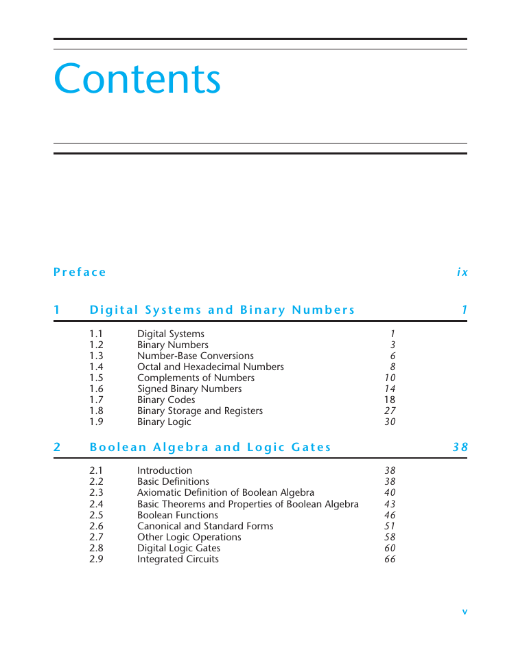
Contents
Preface
1 Digital Systems and Binary Numbers
1.1 Digital Systems
1.2 Binary Numbers
1.3 Number-Base Conversions
1.4 Octal and Hexadecimal Numbers
1.5 Complements of Numbers
1.6 Signed Binary Numbers
1.7 Binary Codes
1.8 Binary Storage and Registers
1.9 Binary Logic
2 Boolean Algebra and Logic Gates
2.1 Introduction
2.2 Basic Definitions
2.3 Axiomatic Definition of Boolean Algebra
2.4 Basic Theorems and Properties of Boolean Algebra
2.5 Boolean Functions
2.6 Canonical and Standard Forms
2.7 Other Logic Operations
2.8 Digital Logic Gates
2.9 Integrated Circuits
3 Gate-Level Minimization
3.1 Introduction
3.2 The Map Method
3.3 Four-Variable K-Map
3.4 Product-of-Sums Simplification
3.5 Don't-Care Conditions
3.6 NAND and NOR Implementation
3.7 Other Two-Level Implementations
3.8 Exclusive-OR Function
3.9 Hardware Description Language
4 Combinational Logic
4.1 Introduction
4.2 Combinational Circuits
4.3 Analysis Procedure
4.4 Design Procedure
4.5 Binary Adder–Subtractor
4.6 Decimal Adder
4.7 Binary Multiplier
4.8 Magnitude Comparator
4.9 Decoders
4.10 Encoders
4.11 Multiplexers
4.12 HDL Models of Combinational Circuits
5 Synchronous Sequential Logic
5.1 Introduction
5.2 Sequential Circuits
5.3 Storage Elements: Latches
5.4 Storage Elements: Flip-Flops
5.5 Analysis of Clocked Sequential Circuits
5.6 Synthesizable HDL Models of Sequential Circuits
5.7 State Reduction and Assignment
5.8 Design Procedure
6 Registers and Counters
6.1 Registers
6.2 Shift Registers
6.3 Ripple Counters
6.4 Synchronous Counters
6.5 Other Counters
6.6 HDL for Registers and Counters
7 Memory and Programmable Logic
7.1 Introduction
7.2 Random-Access Memory
7.3 Memory Decoding
7.4 Error Detection and Correction
7.5 Read-Only Memory
7.6 Programmable Logic Array
7.7 Programmable Array Logic
7.8 Sequential Programmable Devices
8 Design at the Register Transfer Level
8.1 Introduction
8.2 Register Transfer Level Notation
8.3 Register Transfer Level in HDL
8.4 Algorithmic State Machines (ASMs)
8.5 Design Example (ASMD Chart)
8.6 HDL Description of Design Example
8.7 Sequential Binary Multiplier
8.8 Control Logic
8.9 HDL Description of Binary Multiplier
8.10 Design with Multiplexers
8.11 Race-Free Design (Software Race Conditions)
8.12 Latch-Free Design (Why Waste Silicon?)
8.13 Other Language Features
9 Laboratory Experiments with Standard ICs and FPGAs
9.1 Introduction to Experiments
9.2 Experiment 1: Binary and Decimal Numbers
9.3 Experiment 2: Digital Logic Gates
9.4 Experiment 3: Simplification of Boolean Functions
9.5 Experiment 4: Combinational Circuits
9.6 Experiment 5: Code Converters
9.7 Experiment 6: Design with Multiplexers
9.8 Experiment 7: Adders and Subtractors
9.9 Experiment 8: Flip-Flops
9.10 Experiment 9: Sequential Circuits
9.11 Experiment 10: Counters
9.12 Experiment 11: Shift Registers
9.13 Experiment 12: Serial Addition
9.14 Experiment 13: Memory Unit
9.15 Experiment 14: Lamp Handball
9.16 Experiment 15: Clock-Pulse Generator
9.17 Experiment 16: Parallel Adder and Accumulator
9.18 Experiment 17: Binary Multiplier
9.19 Verilog HDL Simulation Experiments and Rapid Prototyping with FPGAs
10 Standard Graphic Symbols
10.1 Rectangular-Shape Symbols
10.2 Qualifying Symbols
10.3 Dependency Notation
10.4 Symbols for Combinational Elements
10.5 Symbols for Flip-Flops
10.6 Symbols for Registers
10.7 Symbols for Counters
10.8 Symbol for RAM
Appendix
Answers to Selected Problems
Index
A
B
C
D
E
F
G
H
I
J
K
L
M
N
O
P
Q
R
S
T
U
V
W
X
Digital Design With an Introduction to the Verilog HDL
This page intentionally left blank
Digital Design With an Introduction to the Verilog HDL FIFTH EDITION M. Morris Mano Emeritus Professor of Computer Engineering California State University, Los Angeles Michael D. Ciletti Emeritus Professor of Electrical and Computer Engineering University of Colorado at Colorado Springs Upper Saddle River Boston Columbus San Franciso New York Indianapolis London Toronto Sydney Singapore Tokyo Montreal Dubai Madrid Hong Kong Mexico City Munich Paris Amsterdam Cape Town
Vice President and Editorial Director, ECS: Marcia J. Horton Executive Editor: Andrew Gilfillan Vice-President, Production: Vince O’Brien Executive Marketing Manager: Tim Galligan Marketing Assistant: Jon Bryant Permissions Project Manager: Karen Sanatar Senior Managing Editor: Scott Disanno Production Project Manager/Editorial Production Manager: Greg Dulles Cover Designer: Jayne Conte Cover Photo: Michael D. Ciletti Composition: Jouve India Private Limited Full-Service Project Management: Jouve India Private Limited Printer/Binder: Edwards Brothers Typeface: Times Ten 10/12 Copyright © 2013, 2007, 2002, 1991, 1984 Pearson Education, Inc., publishing as Prentice Hall, One Lake Street, Upper Saddle River, New Jersey 07458. All rights reserved. Manufactured in the United States of America. This publication is protected by Copyright, and permission should be obtained from the publisher prior to any prohibited reproduction, storage in a retrieval system, or transmission in any form or by any means, electronic, mechanical, photocopying, recording, or likewise. To obtain permission(s) to use material from this work, please submit a written request to Pearson Education, Inc., Permissions Department, One Lake Street, Upper Saddle River, New Jersey 07458. Many of the designations by manufacturers and seller to distinguish their products are claimed as trademarks. Where those designations appear in this book, and the publisher was aware of a trademark claim, the designations have been printed in initial caps or all caps. All rights reserved. No part of this book may be reproduced, in any form or by any means, without permission in writing from the publisher. Verilogger Pro and SynaptiCAD are trademarks of SynaptiCAD, Inc., Blacksburg, VA 24062–0608. The author and publisher of this book have used their best efforts in preparing this book. These efforts include the development, research, and testing of the theories and programs to determine their effectiveness. The author and publisher make no warranty of any kind, expressed or implied, with regard to these programs or the documentation contained in this book. The author and publisher shall not be liable in any event for incidental or consequential damages in connection with, or arising out of, the furnishing, performance, or use of these programs. About the cover: “Spider Rock in Canyon de Chelley,” Chinle, Arizona, USA, January 2011. Photograph courtesy of mdc Images, LLC (www.mdcilettiphotography.com). Used by permission. p. cm. Library of Congress Cataloging-in-Publication Data Mano, M. Morris, 1927– Digital design : with an introduction to the verilog hdl / M. Morris Mano, Michael D. Ciletti.—5th ed. Includes index. ISBN-13: 978-0-13-277420-8 ISBN-10: 0-13-277420-8 1.  Electronic digital computers—Circuits. 2.  Logic circuits. 3.  Logic design. 4.  Digital integrated circuits.  I. Ciletti, Michael D. II. Title. TK7888.3.M343 2011 621.39'5—dc23 2011039094 10 9 8 7 6 5 4 3 2 1 ISBN-13: 978-0-13-277420-8 ISBN-10: 0-13-277420-8
Contents P r e f a c e 1 D i g i t a l S y s t e m s a n d B i n a r y N u m b e r s 1.1 1.2 1.3 1.4 1.5 1.6 1.7 1.8 1.9 Digital Systems Binary Numbers Number‐Base Conversions Octal and Hexadecimal Numbers Complements of Numbers Signed Binary Numbers Binary Codes Binary Storage and Registers Binary Logic 2 B o o l e a n A l g e b r a a n d L o g i c G a t e s 2.1 2.2 2.3 2.4 2.5 2.6 2.7 2.8 2.9 Introduction Basic Definitions Axiomatic Definition of Boolean Algebra Basic Theorems and Properties of Boolean Algebra Boolean Functions Canonical and Standard Forms Other Logic Operations Digital Logic Gates Integrated Circuits 1 3 6 8 10 14 18 27 30 38 38 40 43 46 51 58 60 66 i x 1 3 8 v
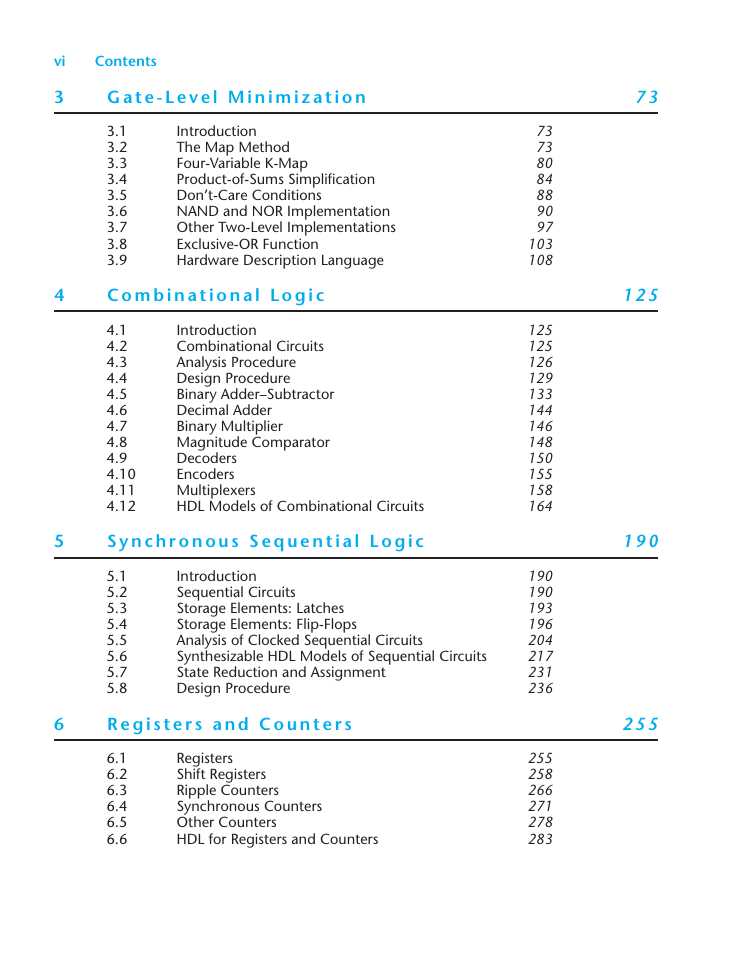
vi Contents 3 G a t e ‐ L e v e l M i n i m i z a t i o n 7 3 3.1 3.2 3.3 3.4 3.5 3.6 3.7 3.8 3.9 Introduction The Map Method Four‐Variable K-Map Product‐of‐Sums Simplification Don’t‐Care Conditions NAND and NOR Implementation Other Two‐Level Implementations Exclusive‐OR Function Hardware Description Language 4 C o m b i n a t i o n a l L o g i c 4.1 4.2 4.3 4.4 4.5 4.6 4.7 4.8 4.9 4.10 4.11 4.12 Introduction Combinational Circuits Analysis Procedure Design Procedure Binary Adder–Subtractor Decimal Adder Binary Multiplier Magnitude Comparator Decoders Encoders Multiplexers HDL Models of Combinational Circuits 5 S y n c h r o n o u s S e q u e n t i a l L o g i c 5.1 5.2 5.3 5.4 5.5 5.6 5.7 5.8 Introduction Sequential Circuits Storage Elements: Latches Storage Elements: Flip‐Flops Analysis of Clocked Sequential Circuits Synthesizable HDL Models of Sequential Circuits State Reduction and Assignment Design Procedure 6 R e g i s t e r s a n d C o u n t e r s 6.1 6.2 6.3 6.4 6.5 6.6 Registers Shift Registers Ripple Counters Synchronous Counters Other Counters HDL for Registers and Counters 73 73 80 84 88 90 97 103 108 125 125 126 129 133 144 146 148 150 155 158 164 190 190 193 196 204 217 231 236 255 258 266 271 278 283 1 2 5 1 9 0 2 5 5
分享到:
收藏