DOCUMENT NUMBER
S12SPIV4/D
SPI
Block Guide
V04.01
Original Release Date: 21 JAN 2000
Revised: 14 JUL 2004
Motorola, Inc.
Motorola reserves the right to make changes without further notice to any products herein. Motorola makes no warranty, representation or guarantee regarding the suitability of its
products for any particular purpose, nor does Motorola assume any liability arising out of the application or use of any product or circuit, and specifically disclaims any and all liability,
including without limitation consequential or incidental damages. “Typical” parameters which may be provided in Motorola data sheets and/or specifications can and do vary in
different applications and actual performance may vary over time. All operating parameters, including “Typicals” must be validated for each customer application by customer’s
technical experts. Motorola does not convey any license under its patent rights nor the rights of others. Motorola products are not designed, intended, or authorized for use as
components in systems intended for surgical implant into the body, or other applications intended to support or sustain life, or for any other application in which the failure of the
Motorola product could create a situation where personal injury or death may occur. Should Buyer purchase or use Motorola products for any such unintended or unauthorized
application, Buyer shall indemnify and hold Motorola and its officers, employees, subsidiaries, affiliates, and distributors harmless against all claims, costs, damages, and expenses,
and reasonable attorney fees arising out of, directly or indirectly, any claim of personal injury or death associated with such unintended or unauthorized use, even if such claim alleges
that Motorola was negligent regarding the design or manufacture of the part. Motorola and
are registered trademarks of Motorola, Inc. Motorola, Inc. is an Equal
Opportunity/Affirmative Action Employer.
©Motorola, Inc., 2001
1
Freescale Semiconductor, I Freescale Semiconductor, Inc.For More Information On This Product, Go to: www.freescale.comnc...�
SPI Block Guide V04.01
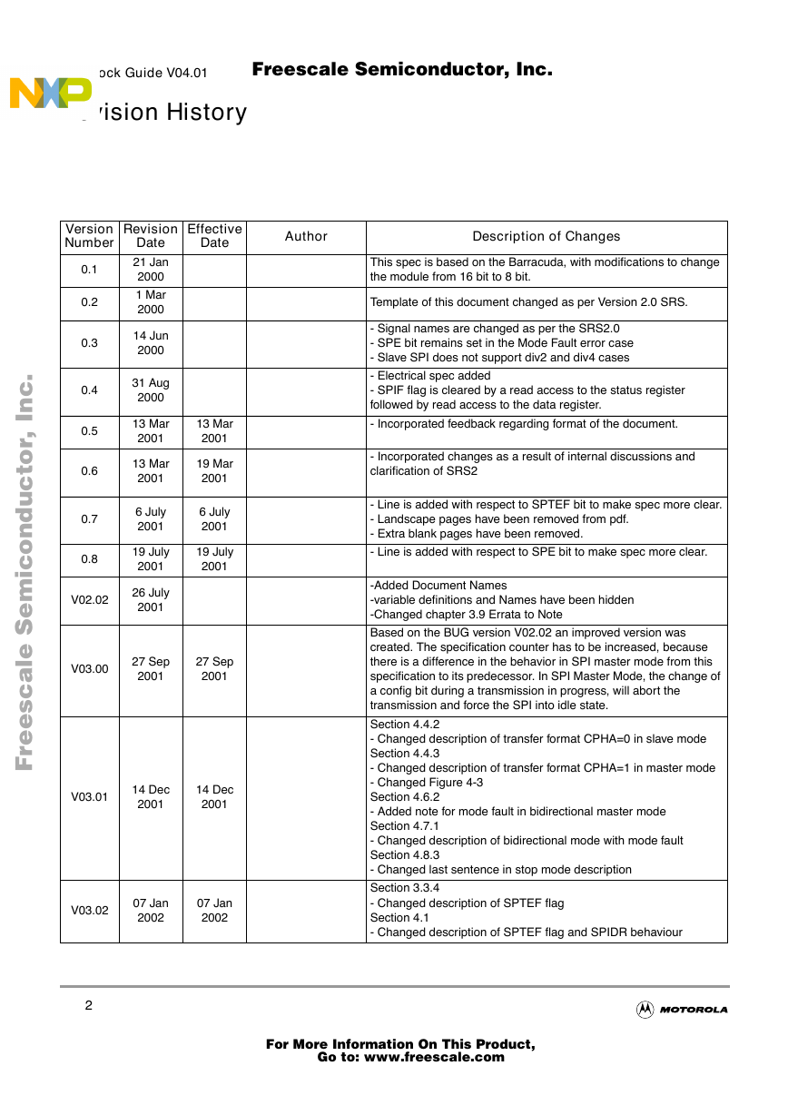
Revision History
Effective
Date
Author
Description of Changes
This spec is based on the Barracuda, with modifications to change
the module from 16 bit to 8 bit.
Template of this document changed as per Version 2.0 SRS.
- Signal names are changed as per the SRS2.0
- SPE bit remains set in the Mode Fault error case
- Slave SPI does not support div2 and div4 cases
- Electrical spec added
- SPIF flag is cleared by a read access to the status register
followed by read access to the data register.
- Incorporated feedback regarding format of the document.
- Incorporated changes as a result of internal discussions and
clarification of SRS2
- Line is added with respect to SPTEF bit to make spec more clear.
- Landscape pages have been removed from pdf.
- Extra blank pages have been removed.
- Line is added with respect to SPE bit to make spec more clear.
-Added Document Names
-variable definitions and Names have been hidden
-Changed chapter 3.9 Errata to Note
Based on the BUG version V02.02 an improved version was
created. The specification counter has to be increased, because
there is a difference in the behavior in SPI master mode from this
specification to its predecessor. In SPI Master Mode, the change of
a config bit during a transmission in progress, will abort the
transmission and force the SPI into idle state.
Section 4.4.2
- Changed description of transfer format CPHA=0 in slave mode
Section 4.4.3
- Changed description of transfer format CPHA=1 in master mode
- Changed Figure 4-3
Section 4.6.2
- Added note for mode fault in bidirectional master mode
Section 4.7.1
- Changed description of bidirectional mode with mode fault
Section 4.8.3
- Changed last sentence in stop mode description
Section 3.3.4
- Changed description of SPTEF flag
Section 4.1
- Changed description of SPTEF flag and SPIDR behaviour
Version
Number
0.1
0.2
0.3
0.4
0.5
0.6
0.7
0.8
V02.02
Revision
Date
21 Jan
2000
1 Mar
2000
14 Jun
2000
31 Aug
2000
13 Mar
2001
13 Mar
2001
6 July
2001
19 July
2001
26 July
2001
13 Mar
2001
19 Mar
2001
6 July
2001
19 July
2001
V03.00
27 Sep
2001
27 Sep
2001
V03.01
14 Dec
2001
14 Dec
2001
V03.02
07 Jan
2002
07 Jan
2002
2
Freescale Semiconductor, I Freescale Semiconductor, Inc.For More Information On This Product, Go to: www.freescale.comnc...�
SPI Block Guide V04.01
Version
Number
V03.03
V03.04
V03.05
V03.06
Revision
Date
09 Jan
2002
18 Mar
2002
03 Apr
2002
04 Feb
2003
Effective
Date
09 JAN
2002
18 Mar
2002
03 Apr
2002
04 Feb
2003
V04.00
02 Jun
2004
02 Jun
2004
Author
Description of Changes
Transferred document to SRS3.0 format
Updated Document Format.
Minor Document cleanup.
Minor Document cleanup.
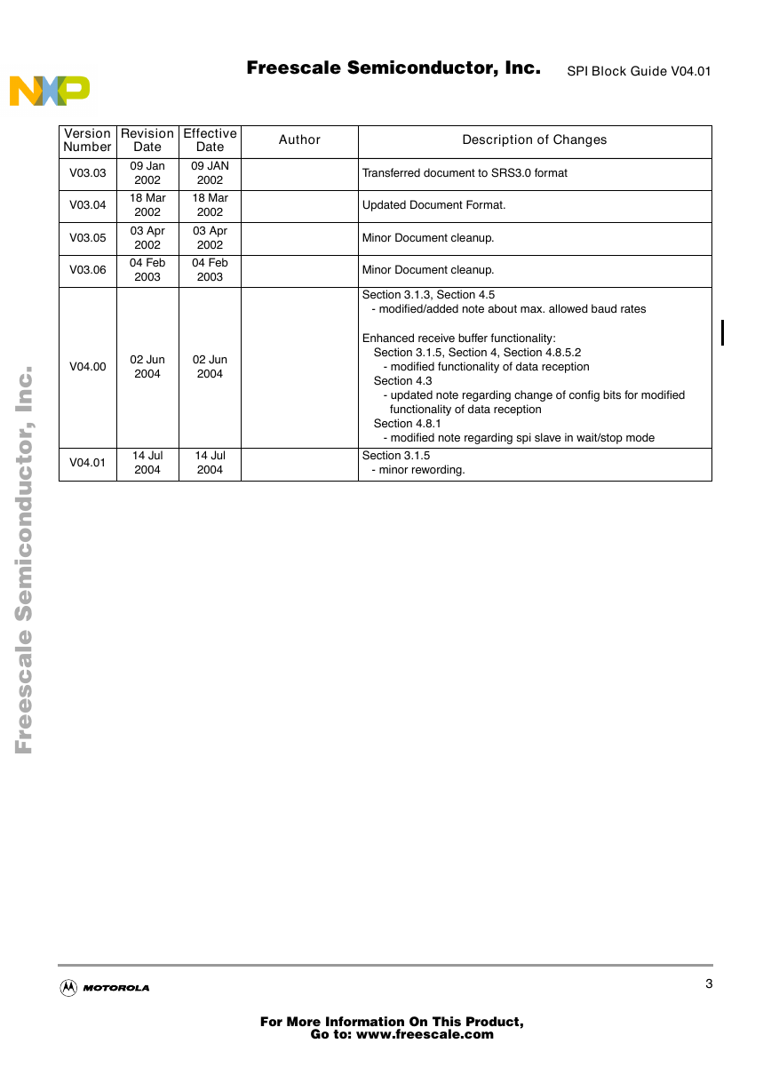
Section 3.1.3, Section 4.5
- modified/added note about max. allowed baud rates
Enhanced receive buffer functionality:
Section 3.1.5, Section 4, Section 4.8.5.2
- modified functionality of data reception
Section 4.3
- updated note regarding change of config bits for modified
functionality of data reception
Section 4.8.1
- modified note regarding spi slave in wait/stop mode
V04.01
14 Jul
2004
14 Jul
2004
Section 3.1.5
- minor rewording.
3
Freescale Semiconductor, I Freescale Semiconductor, Inc.For More Information On This Product, Go to: www.freescale.comnc...�
SPI Block Guide V04.01
4
Freescale Semiconductor, I Freescale Semiconductor, Inc.For More Information On This Product, Go to: www.freescale.comnc...�
Table of Contents
SPI Block Guide V04.01
Section 1 Introduction
1.1
Overview. . . . . . . . . . . . . . . . . . . . . . . . . . . . . . . . . . . . . . . . . . . . . . . . . . . . . . . . . . 13
1.2
Features . . . . . . . . . . . . . . . . . . . . . . . . . . . . . . . . . . . . . . . . . . . . . . . . . . . . . . . . . . 14
1.3 Modes of Operation . . . . . . . . . . . . . . . . . . . . . . . . . . . . . . . . . . . . . . . . . . . . . . . . . 14
Section 2 External Signal Description
2.1
2.2
2.2.1
2.2.2
2.2.3
2.2.4
Overview. . . . . . . . . . . . . . . . . . . . . . . . . . . . . . . . . . . . . . . . . . . . . . . . . . . . . . . . . . 15
Detailed Signal Description . . . . . . . . . . . . . . . . . . . . . . . . . . . . . . . . . . . . . . . . . . . 15
MOSI . . . . . . . . . . . . . . . . . . . . . . . . . . . . . . . . . . . . . . . . . . . . . . . . . . . . . . . . . . 15
MISO . . . . . . . . . . . . . . . . . . . . . . . . . . . . . . . . . . . . . . . . . . . . . . . . . . . . . . . . . . 15
SS . . . . . . . . . . . . . . . . . . . . . . . . . . . . . . . . . . . . . . . . . . . . . . . . . . . . . . . . . . . . 15
SCK . . . . . . . . . . . . . . . . . . . . . . . . . . . . . . . . . . . . . . . . . . . . . . . . . . . . . . . . . . . 15
Section 3 Memory Map/Register Definition
3.1
3.1.1
3.1.2
3.1.3
3.1.4
3.1.5
Register Descriptions . . . . . . . . . . . . . . . . . . . . . . . . . . . . . . . . . . . . . . . . . . . . . . . . 16
SPI Control Register 1 . . . . . . . . . . . . . . . . . . . . . . . . . . . . . . . . . . . . . . . . . . . . . 16
SPI Control Register 2 . . . . . . . . . . . . . . . . . . . . . . . . . . . . . . . . . . . . . . . . . . . . . 18
SPI Baud Rate Register . . . . . . . . . . . . . . . . . . . . . . . . . . . . . . . . . . . . . . . . . . . . 19
SPI Status Register . . . . . . . . . . . . . . . . . . . . . . . . . . . . . . . . . . . . . . . . . . . . . . . 21
SPI Data Register . . . . . . . . . . . . . . . . . . . . . . . . . . . . . . . . . . . . . . . . . . . . . . . . 22
Section 4 Functional Description
4.1
General. . . . . . . . . . . . . . . . . . . . . . . . . . . . . . . . . . . . . . . . . . . . . . . . . . . . . . . . . . . 24
4.2 Master Mode. . . . . . . . . . . . . . . . . . . . . . . . . . . . . . . . . . . . . . . . . . . . . . . . . . . . . . . 24
4.3
Slave Mode. . . . . . . . . . . . . . . . . . . . . . . . . . . . . . . . . . . . . . . . . . . . . . . . . . . . . . . . 25
Transmission Formats . . . . . . . . . . . . . . . . . . . . . . . . . . . . . . . . . . . . . . . . . . . . . . . 26
4.4
Clock Phase and Polarity Controls. . . . . . . . . . . . . . . . . . . . . . . . . . . . . . . . . . . . 27
4.4.1
4.4.2
CPHA = 0 Transfer Format . . . . . . . . . . . . . . . . . . . . . . . . . . . . . . . . . . . . . . . . . 27
CPHA = 1 Transfer Format . . . . . . . . . . . . . . . . . . . . . . . . . . . . . . . . . . . . . . . . . 29
4.4.3
SPI Baud Rate Generation . . . . . . . . . . . . . . . . . . . . . . . . . . . . . . . . . . . . . . . . . . . . 30
4.5
4.6
Special Features. . . . . . . . . . . . . . . . . . . . . . . . . . . . . . . . . . . . . . . . . . . . . . . . . . . . 31
SS Output. . . . . . . . . . . . . . . . . . . . . . . . . . . . . . . . . . . . . . . . . . . . . . . . . . . . . . . 31
4.6.1
4.6.2
Bidirectional Mode (MOMI or SISO). . . . . . . . . . . . . . . . . . . . . . . . . . . . . . . . . . . 31
5
Freescale Semiconductor, I Freescale Semiconductor, Inc.For More Information On This Product, Go to: www.freescale.comnc...�
SPI Block Guide V04.01
4.7
4.7.1
4.8
4.8.1
4.8.2
4.8.3
4.8.4
4.8.5
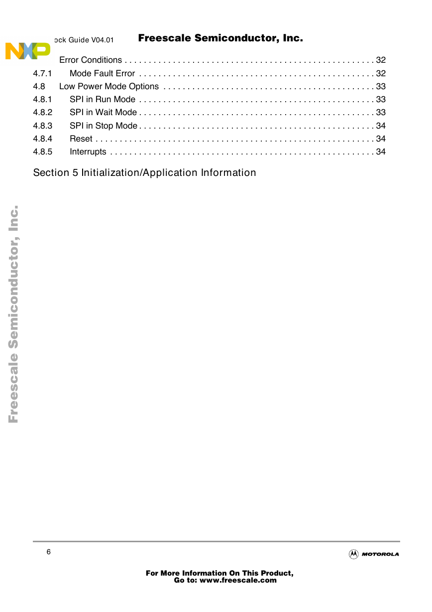
Error Conditions . . . . . . . . . . . . . . . . . . . . . . . . . . . . . . . . . . . . . . . . . . . . . . . . . . . . 32
Mode Fault Error . . . . . . . . . . . . . . . . . . . . . . . . . . . . . . . . . . . . . . . . . . . . . . . . . 32
Low Power Mode Options . . . . . . . . . . . . . . . . . . . . . . . . . . . . . . . . . . . . . . . . . . . . 33
SPI in Run Mode . . . . . . . . . . . . . . . . . . . . . . . . . . . . . . . . . . . . . . . . . . . . . . . . . 33
SPI in Wait Mode . . . . . . . . . . . . . . . . . . . . . . . . . . . . . . . . . . . . . . . . . . . . . . . . . 33
SPI in Stop Mode . . . . . . . . . . . . . . . . . . . . . . . . . . . . . . . . . . . . . . . . . . . . . . . . . 34
Reset . . . . . . . . . . . . . . . . . . . . . . . . . . . . . . . . . . . . . . . . . . . . . . . . . . . . . . . . . . 34
Interrupts . . . . . . . . . . . . . . . . . . . . . . . . . . . . . . . . . . . . . . . . . . . . . . . . . . . . . . . 34
Section 5 Initialization/Application Information
6
Freescale Semiconductor, I Freescale Semiconductor, Inc.For More Information On This Product, Go to: www.freescale.comnc...�
List of Figures
SPI Block Guide V04.01
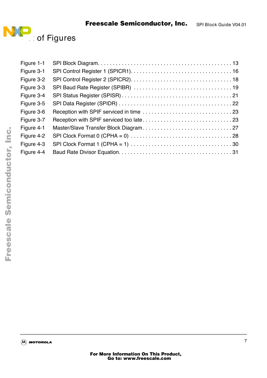
Figure 1-1
SPI Block Diagram. . . . . . . . . . . . . . . . . . . . . . . . . . . . . . . . . . . . . . . . . . . . . 13
Figure 3-1
SPI Control Register 1 (SPICR1). . . . . . . . . . . . . . . . . . . . . . . . . . . . . . . . . . 16
Figure 3-2
SPI Control Register 2 (SPICR2). . . . . . . . . . . . . . . . . . . . . . . . . . . . . . . . . . 18
Figure 3-3
SPI Baud Rate Register (SPIBR) . . . . . . . . . . . . . . . . . . . . . . . . . . . . . . . . . 19
Figure 3-4
SPI Status Register (SPISR) . . . . . . . . . . . . . . . . . . . . . . . . . . . . . . . . . . . . . 21
Figure 3-5
SPI Data Register (SPIDR) . . . . . . . . . . . . . . . . . . . . . . . . . . . . . . . . . . . . . . 22
Figure 3-6 Reception with SPIF serviced in time . . . . . . . . . . . . . . . . . . . . . . . . . . . . . . 23
Figure 3-7 Reception with SPIF serviced too late . . . . . . . . . . . . . . . . . . . . . . . . . . . . . . 23
Figure 4-1 Master/Slave Transfer Block Diagram . . . . . . . . . . . . . . . . . . . . . . . . . . . . . . 27
SPI Clock Format 0 (CPHA = 0) . . . . . . . . . . . . . . . . . . . . . . . . . . . . . . . . . . 28
Figure 4-2
Figure 4-3
SPI Clock Format 1 (CPHA = 1) . . . . . . . . . . . . . . . . . . . . . . . . . . . . . . . . . . 30
Baud Rate Divisor Equation. . . . . . . . . . . . . . . . . . . . . . . . . . . . . . . . . . . . . . 31
Figure 4-4
7
Freescale Semiconductor, I Freescale Semiconductor, Inc.For More Information On This Product, Go to: www.freescale.comnc...�
SPI Block Guide V04.01
8
Freescale Semiconductor, I Freescale Semiconductor, Inc.For More Information On This Product, Go to: www.freescale.comnc...�



 2023年江西萍乡中考道德与法治真题及答案.doc
 2012年重庆南川中考生物真题及答案.doc
 2013年江西师范大学地理学综合及文艺理论基础考研真题.doc
 2020年四川甘孜小升初语文真题及答案I卷.doc
 2020年注册岩土工程师专业基础考试真题及答案.doc
 2023-2024学年福建省厦门市九年级上学期数学月考试题及答案.doc
 2021-2022学年辽宁省沈阳市大东区九年级上学期语文期末试题及答案.doc
 2022-2023学年北京东城区初三第一学期物理期末试卷及答案.doc
 2018上半年江西教师资格初中地理学科知识与教学能力真题及答案.doc
 2012年河北国家公务员申论考试真题及答案-省级.doc
 2020-2021学年江苏省扬州市江都区邵樊片九年级上学期数学第一次质量检测试题及答案.doc
 2022下半年黑龙江教师资格证中学综合素质真题及答案.doc