11111
Electronic Emission Notices
Electronic Emission Notices
Electronic Emission Notices
Electronic Emission Notices
Electronic Emission Notices
Federal Communications Commission (FCC) Statement (425628)
Federal Communications Commission (FCC) Statement (425628)
Federal Communications Commission (FCC) Statement (425628)
Federal Communications Commission (FCC) Statement (425628)
Federal Communications Commission (FCC) Statement (425628)
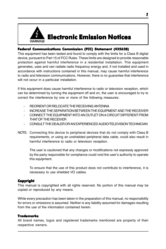
This equipment has been tested and found to comply with the limits for a Class B digital
device, pursuant to Part 15 of FCC Rules. These limits are designed to provide reasonable
protection against harmful interference in a residential installation. This equipment
generates, uses and can radiate radio frequency energy and, if not installed and used in
accordance with instructions contained in this manual, may cause harmful interference
to radio and television communications. However, there is no guarantee that interference
will not occur in a particular installation.
If this equipment does cause harmful interference to radio or television reception, which
can be determined by turning the equipment off and on, the user is encouraged to try to
correct the interference by one or more of the following measures:
- REORIENT OR RELOCATE THE RECEIVING ANTENNA
-
INCREASE THE SEPARATION BETWEEN THE EQUIPMENT AND THE RECEIVER
- CONNECT THE EQUIPMENT INTO AN OUTLET ON A CIRCUIT DIFFERENT FROM
THAT OF THE RECEIVER
- CONSULT THE DEALER OR AN EXPERIENCED AUDIO/TELEVISION TECHNICIAN
NOTE: Connecting this device to peripheral devices that do not comply with Class B
requirements, or using an unshielded peripheral data cable, could also result in
harmful interference to radio or television reception.
The user is cautioned that any changes or modifications not expressly approved
by the party responsible for compliance could void the user’s authority to operate
this equipment.
To ensure that the use of this product does not contribute to interference, it is
necessary to use shielded I/O cables.
Copyright
Copyright
Copyright
Copyright
Copyright
This manual is copyrighted with all rights reserved. No portion of this manual may be
copied or reproduced by any means.
While every precaution has been taken in the preparation of this manual, no responsibility
for errors or omissions is assumed. Neither is any liability assumed for damages resulting
from the use of the information contained herein.
Trademarks
Trademarks
Trademarks
Trademarks
Trademarks
All brand names, logos and registered trademarks mentioned are property of their
respective owners.
�
22222
able of Contents
able of Contents
TTTTTable of Contents
able of Contents
able of Contents
HARDWARE CONFIGURATION
HARDWARE CONFIGURATION
....................................................................
....................................................................
.................................................................... 33333
HARDWARE CONFIGURATION ....................................................................
....................................................................
HARDWARE CONFIGURATION
HARDWARE CONFIGURATION
Key Features ............................................................................................................... 3
Motherboard Layout .................................................................................................... 6
Jumper Settings ........................................................................................................... 7
CPU Speed Selection ............................................................................................ 7
JP1 - System Bus Frequency(only for 845G/GE/PE/GV) .................................... 7
JP2 - CMOS Clear .................................................................................................. 7
JP5 - Keyboard Power Select .............................................................................. 7
JP6 - On Board AC97 Codec Sound .................................................................... 7
SW1 - Code to Voltage Definition (optional) ......................................................... 8
Pin Assignment ..................................................................................................... 9
HARDWARE SETUP
HARDWARE SETUP
......................................................................................
......................................................................................
...................................................................................... 1010101010
HARDWARE SETUP ......................................................................................
HARDWARE SETUP
HARDWARE SETUP
......................................................................................
To Install DDR DIMMs ................................................................................................... 10
Installing a New Processor ......................................................................................... 11
To Install a Processor to ZIF Socket ........................................................................... 11
Connect the Processor Fan Connector ...................................................................... 11
Setting the Processor Speed ...................................................................................... 11
BIOS SETUP
BIOS SETUP
..................................................................................................
..................................................................................................
.................................................................................................. 1212121212
BIOS SETUP ..................................................................................................
BIOS SETUP
..................................................................................................
BIOS SETUP
Starting Setup .............................................................................................................. 12
Main Menu .................................................................................................................... 13
Standard CMOS Features ........................................................................................... 14
Advanced BIOS Features ........................................................................................... 16
Advanced Chipset Features ....................................................................................... 16
Integrated Peripherals ................................................................................................. 16
Power Management Setup .......................................................................................... 16
PNP/PCI Configurations ................................................................................................ 16
PC Health Status .......................................................................................................... 16
Frequency/Voltage Control ......................................................................................... 16
Set Supervisor/User Password .................................................................................. 16
Flash Update Procedure ............................................................................................. 18
APPENDIX
APPENDIX
....................................................................................................
....................................................................................................
.................................................................................................... 1919191919
APPENDIX ....................................................................................................
APPENDIX
APPENDIX
....................................................................................................
USB 2.0 Driver Installation for Windows 9X ........................................................... 19
Technical Reference Booklet
�
33333
ARE CONFIGURATIONTIONTIONTIONTION
ARE CONFIGURA
ARE CONFIGURA
HARDHARDHARDHARDHARDWWWWWARE CONFIGURA
ARE CONFIGURA
Key Key Key Key Key Features
Features
Features
Features : : : : :
Features
Chipset
Chipset
Chipset
Chipset
Chipset
•
Intel® 845G/GL/GE/PE/GV Chipset.
Processor
Processor
Processor
Processor
Processor
•
•
•
Supports the Intel® Pentium® 4 processors and the Northwood
processors in the 478-pin package.
Supports PSB (Processor System Bus) frequency of 400MHz
(100MHz bus clock).
Supports PSB (Processor System Bus) frequency of 533MHz
(133MHz bus clock) (only for 845G,845GE,845PE,845GV).
VRM 9.0 (V
VRM 9.0 (V
oltage R
oltage R
egulator Modules) on Board
egulator Modules) on Board
oltage Regulator Modules) on Board
VRM 9.0 (Voltage R
egulator Modules) on Board
oltage R
VRM 9.0 (V
VRM 9.0 (V
egulator Modules) on Board
•
Flexible motherboard design with on board VRM 9.0, easy to upgrade with
future Intel® Pentium® 4 and Northwood processors.
Cache
Cache
Cache
Cache
Cache
•
The Intel® Pentium® 4 and Northwood processors built-in L2 Cache.
System Memory
System Memory
System Memory
System Memory
System Memory
Supports up to two DDR DIMMs, single-sided or double-sided.
Supports DDR200/266 unregistered, 184-pin non-ECC DDR SDRAM DIMMs.
• Up to 2.0 Gbytes of 200MHz or 266MHz DDR SDRAM.
•
•
• Does not support double-sided x16 DDR DIMMs.
• Up to 2.0 Gbytes of 333MHz DDR SDRAM (only for 845GE/PE/GV).
AGP Controller (only for 845G/845GE/845PE)
AGP Controller (only for 845G/845GE/845PE)
AGP Controller (only for 845G/845GE/845PE)
AGP Controller (only for 845G/845GE/845PE)
AGP Controller (only for 845G/845GE/845PE)
•
•
Supports AGP2.0 including 1x/2x/4x AGP data transfers and 2x/4x Fast Write
protocol.
AGP 1.5V connector support only, No support for 3.3V or Universal AGP
connectors.
• High priority access support.
• Delayed transaction support for AGP reads that cannot be serviced
immediately.
On-board I/O
On-board I/O
On-board I/O
On-board I/O
On-board I/O
• On board two PCI fast IDE ports supporting up to 4 ATA, ATA2 , Ultra ATA33/
66/100 IDE HDDs, CD-ROMs, ZIP drives and LS-120 drives as boot drive.
• One ECP/EPP parallel port.
•
• One floppy port supports two FDD of 360KB, 720KB, 1.2MB , 1.44MB and
Two 16550 Compatible UART serial ports.
2.88MB capacity.
PS/2 keyboard connector.
PS/2 mouse is supported.
•
•
• One front panel sound connector.
•
Infrared (IrDA) is supported via a header.
Expanded USB Support
Expanded USB Support
Expanded USB Support
Expanded USB Support
Expanded USB Support
•
•
Includes 3 UHCI host controllers,increasing the number of external ports to six.
Includes 1 EHCI USB2.0 Host Controller that supports all six ports (Bandwidth
shared between six ports).
Hardware Configuration
�
44444
On-board VGA (only for 845G/845GE/845GL/845GV)
On-board VGA (only for 845G/845GE/845GL/845GV)
On-board VGA (only for 845G/845GE/845GL/845GV)
On-board VGA (only for 845G/845GE/845GL/845GV)
On-board VGA (only for 845G/845GE/845GL/845GV)
3D Setup Render Engine.
3D Graphics Rasterization Enhancements.
Full 2D H/W Acceleration.
• Core Frequency of 200MHz.
•
• High Quality Texture Engine.
•
•
• Motion Video Acceleration.
• Up to 1600x1200 in 8 bit Color at 85MHz Refresh.
• H/W Motion Compensation Assistance for S/W MPEG2 Decode.
•
•
Software DVD at 30fps.
Integrated 24-bit 230MHz RAMDAC.
System BIOS
System BIOS
System BIOS
System BIOS
System BIOS
•
•
•
•
PnP, APM, ATAPI and Windows 95/98/2000.
Full support of ACPI & DMI.
Auto detects and supports LBA harddisks with capacities over 8.4GB.
Easy to upgrade BIOS by end-user.
Plug and Play
Plug and Play
Plug and Play
Plug and Play
Plug and Play
•
•
•
Supports Plug and Play specification 1.1.
Plug and play for DOS, Windows 3.X, Windows 95/98/2000, as well as
Windows XP.
Fully steerable PCI interrupts.
Power Management
Power Management
Power Management
Power Management
Power Management
Supports SMM, APM and ACPI.
Break switch for instant suspend/resume on system operations.
Energy star “Green PC” compliant.
•
•
•
• Hardware monitoring circuit is supported, provide voltage, fan speed,
etc. monitoring (optional).
• WOL (Wake-On-Lan) Header support.
•
•
External Modem Ring-in Wake-up support.
Supports suspend-to-RAM(STR)(optional).
On-board AC97 Sound (optional)
On-board AC97 Sound (optional)
On-board AC97 Sound (optional)
On-board AC97 Sound (optional)
On-board AC97 Sound (optional)
Integrated AC97 controller with standard AC97 Codec.
•
• Direct Sound and Sound Blaster compatible.
•
•
• Win95/98/2000, NT drivers ready.
•
Full-Duplex 16-Bit record and play back.
PnP and APM 1.2 support.
Line-in, Line-out, Mic-in and MIDI/Game port.
Technical Reference Booklet
�
On-board PCI Sound (optional)
On-board PCI Sound (optional)
On-board PCI Sound (optional)
On-board PCI Sound (optional)
On-board PCI Sound (optional)
55555
Full DOS game support.(DDMA, PC/PCI, CLS).
PCI 2.1 Bus Master, hardware sound acceleration.
•
•
• Direct Sound and Sound Blaster compatible.
•
•
Full Duplex, Crystal 3D Enhancement, Software Wavetable.
PnP and APM 1.2 support.
Expansion Slots
Expansion Slots
Expansion Slots
Expansion Slots
Expansion Slots
•
•
•
1 CNR slot (shares 1 PCI slot) (optional).
1 AGP slot (845GL/GV supports ADD card only,
845G/GE/PE supports ADD card)(optional).
6 PCI bus master slots - ver. 2.1 compliant (1 PCI shares with 1 CNR slot).
CAUTION
Static electricity can harm delicate components of the motherboard. To prevent
damage caused by static electricity, discharge the static electricity from your
body before you touch any of the computers electronic components.
Hardware Configuration
�
66666
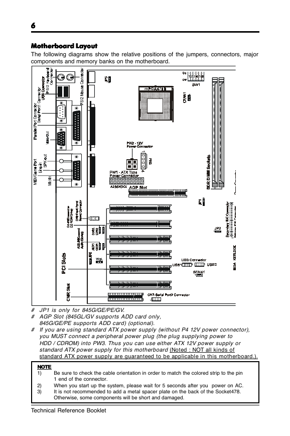
Motherboard Layout
Motherboard Layout
Motherboard Layout
Motherboard Layout
Motherboard Layout
The following diagrams show the relative positions of the jumpers, connectors, major
components and memory banks on the motherboard.
# JP1 is only for 845G/GE/PE/GV.
# AGP Slot (845GL/GV supports ADD card only,
845G/GE/PE supports ADD card) (optional).
# If you are using standard ATX power supply (without P4 12V power connector),
you MUST connect a peripheral power plug (the plug supplying power to
HDD / CDROM) into PW3. Thus you can use either ATX 12V power supply or
standard ATX power supply for this motherboard (Noted : NOT all kinds of
standard ATX power supply are guaranteed to be applicable in this motherboard.).
NOTE
1)
2)
3)
Be sure to check the cable orientation in order to match the colored strip to the pin
1 end of the connector.
When you start up the system, please wait for 5 seconds after you power on AC.
It is not recommended to add a metal spacer plate on the back of the Socket478.
Otherwise, some components will be short and damaged.
Technical Reference Booklet
�
Jumper Settings
Jumper Settings
Jumper Settings
Jumper Settings
Jumper Settings
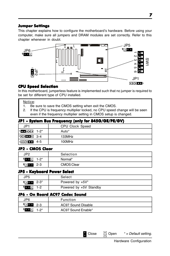
This chapter explains how to configure the motherboard’s hardware. Before using your
computer, make sure all jumpers and DRAM modules are set correctly. Refer to this
chapter whenever in doubt.
77777
JP6
1
J
P
2
JP5
S
W
1
1
2
3
4
5
6
JP1
CPU Speed Selection
CPU Speed Selection
CPU Speed Selection
CPU Speed Selection
CPU Speed Selection
In this motherboard, jumperless feature is implemented such that no jumper is required to
be set for different type of CPU installed.
1
Notice:
1. Be sure to save the CMOS setting when exit the CMOS.
2.
If the CPU is frequency multiplier locked, no CPU speed change will be seen
even if the frequency multiplier setting in CMOS setup is changed.
JP1 - System Bus Frequency (only for 845G/GE/PE/GV)
JP1 - System Bus Frequency (only for 845G/GE/PE/GV)
JP1 - System Bus Frequency (only for 845G/GE/PE/GV)
JP1 - System Bus Frequency (only for 845G/GE/PE/GV)
JP1 - System Bus Frequency (only for 845G/GE/PE/GV)
JP1
1
1
1
1-2*
3-4
4-5
JP2 - CMOS Clear
JP2 - CMOS Clear
JP2 - CMOS Clear
JP2 - CMOS Clear
JP2 - CMOS Clear
JP2
1-2*
2-3
CPU Clock Speed
Auto*
133MHz
100MHz
Selection
Normal*
CMOS Clear
JP5
JP5 - Keyboard Power Select
JP5 - Keyboard Power Select
JP5 - Keyboard Power Select
JP5 - Keyboard Power Select
JP5 - Keyboard Power Select
Select
Powered by +5V*
Powered by +5V Standby
2-3*
1-2
JP6 - On Board AC97 Codec Sound
JP6 - On Board AC97 Codec Sound
JP6 - On Board AC97 Codec Sound
JP6 - On Board AC97 Codec Sound
JP6 - On Board AC97 Codec Sound
JP6
2-3
1-2*
Function
AC97 Sound Disable
AC97 Sound Enable*
Close
Open * = Default setting.
Hardware Configuration
�
88888
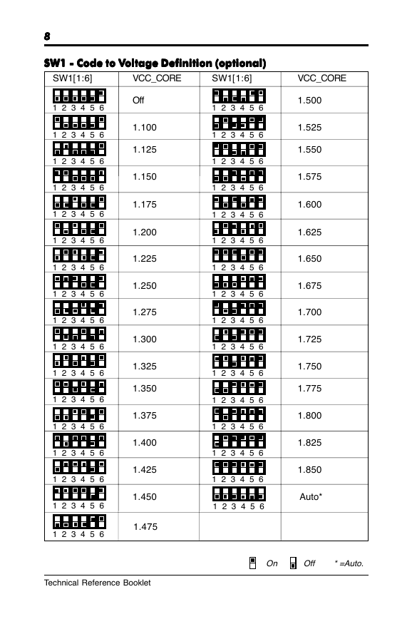
SW1 - Code to V
SW1 - Code to V
oltage Definition (optional)
oltage Definition (optional)
SW1 - Code to Voltage Definition (optional)
oltage Definition (optional)
SW1 - Code to V
SW1 - Code to V
oltage Definition (optional)
SW1[1:6]
VCC_CORE
SW1[1:6]
1 2 3 4 5 6
1 2 3 4 5 6
1 2 3 4 5 6
1 2 3 4 5 6
1 2 3 4 5 6
1 2 3 4 5 6
1 2 3 4 5 6
1 2 3 4 5 6
1 2 3 4 5 6
1 2 3 4 5 6
1 2 3 4 5 6
1 2 3 4 5 6
1 2 3 4 5 6
1 2 3 4 5 6
1 2 3 4 5 6
1 2 3 4 5 6
1 2 3 4 5 6
Off
1.100
1.125
1.150
1.175
1.200
1.225
1.250
1.275
1.300
1.325
1.350
1.375
1.400
1.425
1.450
1.475
1 2 3 4 5 6
1 2 3 4 5 6
1 2 3 4 5 6
1 2 3 4 5 6
1 2 3 4 5 6
1 2 3 4 5 6
1 2 3 4 5 6
1 2 3 4 5 6
1 2 3 4 5 6
1 2 3 4 5 6
1 2 3 4 5 6
1 2 3 4 5 6
1 2 3 4 5 6
1 2 3 4 5 6
1 2 3 4 5 6
1 2 3 4 5 6
VCC_CORE
1.500
1.525
1.550
1.575
1.600
1.625
1.650
1.675
1.700
1.725
1.750
1.775
1.800
1.825
1.850
Auto*
Technical Reference Booklet
On Off * =Auto.
�



 2023年江西萍乡中考道德与法治真题及答案.doc
 2012年重庆南川中考生物真题及答案.doc
 2013年江西师范大学地理学综合及文艺理论基础考研真题.doc
 2020年四川甘孜小升初语文真题及答案I卷.doc
 2020年注册岩土工程师专业基础考试真题及答案.doc
 2023-2024学年福建省厦门市九年级上学期数学月考试题及答案.doc
 2021-2022学年辽宁省沈阳市大东区九年级上学期语文期末试题及答案.doc
 2022-2023学年北京东城区初三第一学期物理期末试卷及答案.doc
 2018上半年江西教师资格初中地理学科知识与教学能力真题及答案.doc
 2012年河北国家公务员申论考试真题及答案-省级.doc
 2020-2021学年江苏省扬州市江都区邵樊片九年级上学期数学第一次质量检测试题及答案.doc
 2022下半年黑龙江教师资格证中学综合素质真题及答案.doc