Front Cover
Op Amps for Everyone
Op Amps for Everyone
Copyright
Dedication
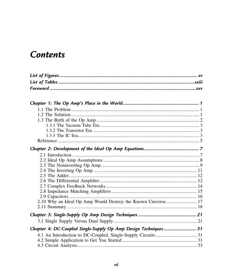
Contents
List of Figures
List of Tables
Foreword
The Changing World
1 - The Op Amp's Place in the World
1.1 The Problem
1.2 The Solution
1.3 The Birth of the Op Amp
1.3.1 The Vacuum Tube Era
1.3.2 The Transistor Era
1.3.3 The IC Era
Reference
2 - Development of the Ideal Op Amp Equations
2.1 Introduction
2.2 Ideal Op Amp Assumptions
2.3 The Noninverting Op Amp
2.4 The Inverting Op Amp
2.5 The Adder
2.6 The Differential Amplifier
2.7 Complex Feedback Networks
2.8 Impedance Matching Amplifiers
2.9 Capacitors
2.10 Why an Ideal Op Amp Would Destroy the Known Universe
2.11 Summary
3 - Single-Supply Op Amp Design Techniques
3.1 Single Supply Versus Dual Supply
4 - DC-Coupled Single-Supply Op Amp Design Techniques
4.1 An Introduction to DC-Coupled, Single-Supply Circuits
4.2 Simple Application to Get You Started
4.3 Circuit Analysis
4.4 Simultaneous Equations
4.4.1 Case 1: VOUT=+mVIN+b
4.4.2 Case 2: VOUT=+mVIN−b
4.4.3 Case 3: VOUT=−mVIN+b
4.4.4 Case 4: VOUT=−mVIN−b
4.5 Summary
5 - On Beyond Case 4
5.1 A Continuum of Applications
5.2 Noninverting Attenuator With Zero Offset
5.3 Noninverting Attenuation With Positive Offset
5.4 Noninverting Attenuation With Negative Offset
5.5 Inverting Attenuation With Zero Offset
5.6 Inverting Attenuation With Positive Offset
5.7 Inverting Attenuation With Negative Offset
5.8 Noninverting Buffer
5.9 Signal Chain Design
6 - Feedback and Stability Theory
6.1 Introduction to Feedback Theory
6.2 Block Diagram Math and Manipulations
6.3 Feedback Equation and Stability
6.4 Bode Analysis of Feedback Circuits
6.5 Bode Analysis Applied to Op Amps
6.6 Loop Gain Plots Are the Key to Understanding Stability
6.7 The Second-Order Equation and Ringing/Overshoot Predictions
References
7 - Development of the Nonideal Op Amp Equations
7.1 Introduction
7.2 Review of the Canonical Equations
7.3 Noninverting Op Amps
7.4 Inverting Op Amps
7.5 Differential Op Amps
7.6 Are You Smarter Than an Op Amp?
8 - Voltage-Feedback Op Amp Compensation
8.1 Introduction
8.2 Internal Compensation
8.3 External Compensation, Stability, and Performance
8.4 Dominant-Pole Compensation
8.5 Gain Compensation
8.6 Lead Compensation
8.7 Compensated Attenuator Applied to Op Amp
8.8 Lead-Lag Compensation
8.9 Comparison of Compensation Schemes
8.10 Conclusions
9 - Current-Feedback Op Amps
9.1 Introduction
9.2 Current-Feedback Amplifier Model
9.3 Development of the Stability Equation
9.4 The Noninverting Current-Feedback Amplifier
9.5 The Inverting Current-Feedback Amplifier
9.6 Stability Analysis
9.7 Selection of the Feedback Resistor
9.8 Stability and Input Capacitance
9.9 Stability and Feedback Capacitance
9.10 Compensation of CF and CG
9.11 Summary
10 - Voltage- and Current-Feedback Op Amp Comparison
10.1 Introduction
10.2 Precision
10.3 Bandwidth
10.4 Stability
10.5 Impedance
10.6 Equation Comparison
11 - Fully Differential Op Amps
11.1 Introduction
11.2 What Does “Fully Differential” Mean?
11.3 How is the Second Output Used?
11.4 Differential Gain Stages
11.5 Single-Ended to Differential Conversion
11.6 A New Function
11.7 Conceptualizing the Vocm Input
11.8 Instrumentation
11.9 Filter Circuits
11.9.1 Single-Pole Filters
11.9.2 Double-Pole Filters
11.9.3 Multiple Feedback Filters
11.9.4 Biquad Filter
12 - Different Types of Op Amps
12.1 Introduction
12.2 Uncompensated/Undercompensated Voltage-Feedback Op Amps
12.3 Instrumentation Amplifier
12.4 Difference Amplifier
12.5 Buffer Amplifiers
13 - Troubleshooting—What to Do When Things Go Wrong
13.1 Introduction
13.2 Simple Things First—Check the Power!
13.3 Do Not Forget That Enable Pin
13.4 Check the DC Operating Point
13.5 The Gain Is Wrong
13.6 The Output Is Noisy
13.6.1 Conducted Emissions and Radiated Emissions
13.6.2 Radiated Susceptibility
13.6.3 Conducted Susceptibility
13.7 The Output Has an Offset
13.8 Conclusion
14 - Interfacing a Transducer to an Analog to Digital Converter
14.1 Introduction
14.2 System Information
14.3 Power Supply Information
14.4 Input Signal Characteristics
14.5 Analog to Digital Converter Characteristics
14.6 Interface Characteristics
14.7 Architectural Decisions
14.8 Conclusions
15 - Interfacing D/A Converters to Loads
15.1 Introduction
15.2 Load Characteristics
15.2.1 DC Loads
15.2.2 AC Loads
15.3 Understanding the D/A Converter and Its Specifications
15.3.1 Types of D/A Converters—Understanding the Trade-offs
15.3.2 The Resistor Ladder D/A Converter
15.3.3 The Weighted Resistor D/A Converter
15.3.4 The R/2R D/A Converter
15.3.5 The Sigma Delta D/A Converter
15.4 D/A Converter Error Budget
15.4.1 Accuracy Versus Resolution
15.4.2 DC Application Error Budget
15.4.3 AC Application Error Budget
15.4.3.1 Total Harmonic Distortion
15.4.3.2 Dynamic Range
15.4.4 RF Application Error Budget
15.5 D/A Converter Errors and Parameters
15.5.1 DC Errors and Parameters
15.5.1.1 Offset Error
15.5.1.2 Gain Error
15.5.1.3 Differential Nonlinearity Error
15.5.1.4 Integral Nonlinearity Error
15.5.1.5 Power Supply Rejection Ratio
15.5.2 AC Application Errors and Parameters
15.5.2.1 THD+N
15.5.2.2 Signal-to-Noise and Distortion
15.5.2.3 Effective Number of Bits
15.5.2.4 Spurious-Free Dynamic Range
15.5.2.5 Intermodulation Distortion
15.5.2.6 Settling Time
15.6 Compensating for DAC Capacitance
15.7 Increasing Op Amp Buffer Amplifier Current and Voltage
15.7.1 Current Boosters
15.7.2 Voltage Boosters
15.7.3 Power Boosters
15.7.4 Single-Supply Operation and DC Offsets
16 - Active Filter Design Techniques
16.1 Introduction
16.2 Fundamentals of Low-Pass Filters
16.2.1 Butterworth Low-Pass Filters
16.2.2 Tschebyscheff Low-Pass Filters
16.2.3 Bessel Low-Pass Filters
16.2.4 Quality Factor Q
16.2.5 Summary
16.3 Low-Pass Filter Design
16.3.1 First-Order Low-Pass Filter
16.3.2 Second-Order Low-Pass Filter
16.3.2.1 Sallen–Key Topology
16.3.2.2 Multiple Feedback Low Pass Filter Topology
16.3.3 Higher-Order Low-Pass Filters
16.3.3.1 First Filter
16.3.3.2 Second Filter
16.3.3.3 Third Filter
16.4 High-Pass Filter Design
16.4.1 First-Order High-Pass Filter
16.4.2 Second-Order High-Pass Filter
16.4.2.1 Sallen–Key Topology
16.4.2.2 Multiple Feedback High Pass Filter Topology
16.4.3 Higher-Order High-Pass Filter
16.4.3.1 First Filter
16.4.3.2 Second Filter
16.5 Band-Pass Filter Design
16.5.1 Second-Order Band-Pass Filter
16.5.1.1 Sallen–Key Topology
16.5.1.2 Multiple Feedback Band Pass Filter Topology
16.5.2 Fourth-Order Band-Pass Filter (Staggered Tuning)
16.6 Band-Rejection Filter Design
16.6.1 Active Twin-T Filter
16.6.2 Active Wien-Robinson Filter
16.7 All-Pass Filter Design
16.7.1 First-Order All-Pass Filter
16.7.2 Second-Order All-Pass Filter
16.7.3 Higher-Order All-Pass Filter
16.8 Practical Design Hints
16.8.1 Filter Circuit Biasing
16.8.2 Capacitor Selection
16.8.3 Component Values
16.8.4 Op Amp Selection
16.9 Filter Coefficient Tables
Further Reading
17 - Fast, Simple Filter Design
17.1 Introduction
17.2 Fast, Practical Filter Design
17.3 Designing the Filter
17.3.1 Low-Pass Filter (Fig. 17.6)
17.3.2 High-Pass Filter (Fig. 17.7)
17.3.3 Narrow (Single-Frequency) Band-Pass Filter (Fig. 17.8)
17.3.4 Wide Band-Pass Filter (Fig. 17.9)
17.3.5 Notch (Single-Frequency Rejection) Filter (Fig. 17.10)
17.4 Getting the Most Out of a Single Op Amp
17.4.1 Three-Pole Low-Pass Filters
17.4.2 Three-Pole High-Pass Filters
17.4.3 Stagger-Tuned and Multiple-Peak Band-Pass Filters
17.4.4 Single-Amplifier Notch and Multiple Notch Filters
17.4.5 Combination Band-Pass and Notch Filters
17.5 Design Aids
17.5.1 Low-Pass, High-Pass, and Band-Pass Filter Design Aids
17.5.2 Notch Filter Design Aids
17.5.3 Twin-T Design Aids
17.6 Summary
18 - High-Speed Filters
18.1 Introduction
18.2 High-Speed Low-Pass Filters
18.3 High-Speed High-Pass Filters
18.4 High-Speed Band-Pass Filters
18.5 High-Speed Notch Filters
18.6 10kHz Notch Filter Results
18.7 Conclusions
19 - Using Op Amps for RF Design
19.1 Introduction
19.2 Voltage Feedback or Current Feedback?
19.3 RF Amplifier Topology
19.4 Op Amp Parameters for RF Designers
19.4.1 Stage Gain
19.4.2 Phase Linearity
19.4.3 Frequency Response Peaking
19.4.4 −1dB Compression Point
19.4.5 Noise Figure
19.5 Wireless Systems
19.5.1 Broadband Amplifiers
19.5.2 IF Amplifiers
19.6 High-Speed Analog Input Drive Circuits
19.7 Conclusions
20 - Designing Low-Voltage Op Amp Circuits
20.1 Introduction
20.2 Critical Specifications
20.2.1 Output Voltage Swing
20.2.2 Dynamic Range
20.2.3 Input Common-Mode Range
20.2.4 Signal-to-Noise Ratio
20.3 Summary
21 - Extreme Applications
21.1 Introduction
21.2 Temperature
21.2.1 Noise
21.2.2 Speed
21.2.3 Output Drive and Stage
21.2.4 DC Parameters
21.2.5 Most Important Parameter of All
21.2.6 Final Parameter Comments
21.3 Packaging
21.3.1 The Integrated Circuit Itself
21.3.2 The Integrated Circuit Package
21.3.3 Connecting the IC
21.3.3.1 PC Board Design
21.3.3.2 Solders
21.3.3.3 Adhesives and Other Methods of Component Retention
21.4 When Failure Is Not an Option
21.5 When It Has to Work for a Really Long Time
21.6 Conclusions
22 - Voltage Regulation
22.1 Introduction
22.2 Regulator Cases
22.2.1 Virtual Ground: “b”=0
22.2.2 Positive and Negative Voltage Regulators: “b”﹥0, “b”<0
22.3 Make or Buy?
22.4 Linear Regulators
22.5 Switching Power Supplies
22.6 A Companion Circuit
22.7 Another Companion Circuit
22.8 Design Aid
22.9 Conclusions
23 - Negative Voltage Regulation
23.1 Introduction
23.2 Positive Regulators
23.3 Parasitic Winding on the Inductor
23.4 Parasitic Inductor
23.5 Referencing the Regulator to −VOUT Instead of Ground
23.6 Other Techniques
23.7 A Negative Load
23.8 Conclusion
24 - Other Applications
24.1 Op Amp Oscillators
24.2 Hybrid Amplifiers and Power Boosters
25 - Common Application Mistakes
25.1 Introduction
25.2 Op Amp Operated at Less Than Unity (or Specified) Gain
25.3 Op Amp Used as a Comparator
25.3.1 The Comparator
25.3.2 The Op Amp
25.4 Improper Termination of Unused Sections
25.5 DC Gain
25.6 Current Source
25.7 Current-Feedback Amplifier: Shorted Feedback Resistor
25.8 Current-Feedback Amplifier: Capacitor in the Feedback Loop
25.9 Fully Differential Amplifier: Incorrect Single-Ended Termination
25.10 Fully Differential Amplifier: Incorrect DC Operating Point
25.11 Fully Differential Amplifier: Incorrect Common-Mode Range
25.12 The Number One Design Mistake!
A - Review of Circuit Theory
A.1 Introduction
A.2 Ohm's Law
A.3 Kirchhoff's Voltage Law
A.4 Kirchhoff's Current Law
A.5 Voltage Divider Rule
A.6 Current Divider Rule
A.7 Thevenin's Theorem
A.8 Superposition
B - Understanding Op Amp Parameters
B.1 Introduction
B.1.1 Absolute Maximum Ratings
B.1.2 Recommended Operating Conditions
B.1.3 Electrical Characteristics
B.2 Temperature Coefficient of the Input Offset Current (αIIO)
B.3 Temperature Coefficient of Input Offset Voltage (αVIO or αVIO)
B.4 Differential Gain Error (AD)
B.5 Gain Margin Parameter (Am)
B.6 Open-Loop Voltage Gain Parameter (AOL)
B.7 Large-Signal Voltage Amplification Gain Condition (AV)
B.8 Differential Large-Signal Voltage Amplification Parameter (AVD)
B.9 Unity Gain Bandwidth Parameter (B1)
B.10 Maximum-Output-Swing Bandwidth Parameter (BOM)
B.11 Bandwidth Parameter (BW)
B.12 Input Capacitance Parameter (Ci)
B.13 Common-Mode Input Capacitance Parameter (Cic or Ci(c))
B.14 Differential Input Capacitance Parameter (Cid)
B.15 Load Capacitance Condition (CL)
B.16 Supply Voltage Sensitivity (ΔVDD±(or CC±)/ΔVIO, or kSVS)
B.17 Common-Mode Rejection Ratio Parameter (CMRR or kCMR)
B.18 Frequency Condition (f)
B.19 Op Amp Gain Bandwidth Product Parameter (GBW)
B.20 Supply Current (Shutdown) Parameter (ICC(SHDN) or IDD(SHDN))
B.21 Supply Current Parameter (ICC or IDD)
B.22 Input Current Range Parameter (II)
B.23 Input Bias Current Parameter (IIB)
B.24 Input Offset Current Parameter (IIO)
B.25 Input Noise Current Parameter (In)
B.26 Output Current Parameter (IO)
B.27 Low-level Output Current Condition (IOL)
B.28 Short-Circuit Output Current Parameters (IOS or ISC)
B.29 Supply Rejection Ratio Parameter (kSVR)
B.30 Power Dissipation Parameter (PD)
B.31 Power Supply Rejection Ratio Parameter (PSRR)
B.32 Junction to Ambient Thermal Resistance Parameter (θJA)
B.33 Junction to Case Thermal Resistance Parameter (θJC)
B.34 Input Resistance Parameter (ri)
B.35 Differential Input Resistance Parameter (rid or ri(d))
B.36 Load Resistance Condition (RL)
B.37 Null Resistance Condition (RL)
B.38 Output Resistance Parameters (ro)
B.39 Signal Source Condition (RS)
B.40 Open-Loop Transresistance Parameters (Rt)
B.41 Op Amp Slew Rate Parameter (SR)
B.42 Operating Free-Air Temperature Condition (TA)
B.43 Turn-Off Time (Shutdown) Parameter (tDIS or t(off))
B.44 Turn-On Time (Shutdown) Parameters (tEN)
B.45 Fall Time Parameter (tf)
B.46 Total Harmonic Distortion Parameter (THD)
B.47 Total Harmonic Distortion Plus Noise Parameter (THD+N)
B.48 Maximum Junction Temperature Parameter (TJ)
B.49 Rise Time Parameter (tr)
B.50 Settling Time Parameter (ts)
B.51 Storage Temperature Parameter (TS or Tstg)
B.52 Supply Voltage Condition (VCC or VDD)
B.53 Input Voltage Range Condition or Parameter (VI)
B.54 Common-Mode Input Voltage Condition (Vic)
B.55 Common-Mode Input Voltage Range Parameter (VICR)
B.56 Differential Input Voltage Parameter (VID)
B.57 Differential Input Voltage Range Parameter (VDIR)
B.58 Turn-on Voltage (Shutdown) Parameter (VIH-SHDN or V(ON))
B.59 Turn-off Voltage (Shutdown) Parameters (VIL-SHDN or V(OFF))
B.60 Input Voltage Condition (VIN)
B.61 Input Offset Voltage Parameter (VIO or VOS)
B.62 Equivalent Input Noise Voltage Parameter (Vn)
B.63 High-Level Output Voltage Condition or Parameter (VOH)
B.64 Low-Level Output Voltage Condition or Parameter (VOL)
B.65 Maximum Peak-to-Peak Output Voltage Swing Parameter (VOM±)
B.66 Peak-to-Peak Output Voltage Swing Condition or Parameter (VO(PP))
B.67 Step Voltage Peak-to-Peak Condition (V(STEP)PP)
B.68 Crosstalk Parameter (XT)
B.69 Output Impedance Parameter (ZO)
B.70 Open-Loop Transimpedance Parameter (Zt)
B.71 Differential Phase Error Parameter (ΦD)
B.72 Phase Margin Parameter (Φm)
B.73 Bandwidth for 0.1dB Flatness
B.74 Case Temperature for 60s
B.75 Continuous Total Dissipation Parameter
B.76 Duration of Short-Circuit Current
B.77 Input Offset Voltage Long-Term Drift Parameter
B.78 Lead Temperature for 10 or 60s
C - Op Amp Noise Theory
C.1 Introduction
C.2 Characterization
C.2.1 Root-Mean-Square Versus P–P Noise
C.2.2 Noise Floor
C.2.3 Signal-to-Noise Ratio
C.2.4 Multiple Noise Sources
C.2.5 Noise Units
C.3 Types of Noise
C.3.1 Shot Noise
C.3.2 Thermal Noise
C.3.3 Flicker Noise
C.3.4 Burst Noise
C.3.5 Avalanche Noise
C.4 Noise Colors
C.4.1 White Noise
C.4.2 Pink Noise
C.4.3 Red/Brown Noise
C.5 Op Amp Noise
C.5.1 The Noise Corner Frequency and Total Noise
C.5.2 The Corner Frequency
D - Circuit Board Layout Techniques
D.1 General Considerations
D.1.1 The Printed Circuit Board Is a Component of the Op Amp Design
D.1.2 Prototype, Prototype, Prototype!
D.1.3 Noise Sources
D.2 Printed Circuit Board Mechanical Construction
D.2.1 Materials—Choosing the Right One for the Application
D.2.2 Cladding and Plating
D.2.3 How Many Layers Are Best?
D.2.3.1 Single-Sided
D.2.3.2 Double-Sided
D.2.3.3 Multilayer
D.3 Grounding
D.3.1 The Most Important Rule: Keep Grounds and Powers Separate
D.3.2 Other Ground Rules
D.3.3 A Good Example
D.4 The Frequency Characteristics of Passive Components
D.4.1 Resistors
D.4.2 Capacitors
D.4.3 Inductors
D.4.4 Unexpected Printed Circuit Board Passive Components
D.4.4.1 Printed Circuit Board Trace Characteristics
D.4.4.2 Trace Antennas
D.4.4.2.1 Whip Antennas
D.4.4.2.2 Loop Antennas
D.4.4.3 Trace Reflections
D.4.4.4 Trace-to-Plane Capacitors
D.4.4.5 Trace-to-Trace Capacitors and Inductors
D.4.4.6 Inductive Vias
D.4.4.7 Flux Residue Resistance
D.5 Decoupling
D.5.1 Digital Circuitry—A Major Problem for Analog Circuitry
D.5.2 Choosing the Right Capacitor
D.5.3 Decoupling at the IC Level
D.5.4 Decoupling at the Board Level
D.6 Input and Output Isolation
D.7 Packages
D.8 Summary
D.8.1 General
D.8.2 Board Structure
D.8.3 Components
D.8.4 Routing
D.8.5 Bypass
E - Single-Supply Circuit Collection
E.1 Introduction
E.2 Attenuation
E.3 Simulated Inductor
E.4 Precision Rectifier
E.5 AC to DC Converter
E.6 Full-Wave Rectifier
E.7 Tone Control
E.8 Curve Fitting Filters
Index
A
B
C
D
E
F
G
H
I
J
K
L
M
N
O
P
Q
R
S
T
U
V
W
Z
Back Cover


 2023年江西萍乡中考道德与法治真题及答案.doc
 2012年重庆南川中考生物真题及答案.doc
 2013年江西师范大学地理学综合及文艺理论基础考研真题.doc
 2020年四川甘孜小升初语文真题及答案I卷.doc
 2020年注册岩土工程师专业基础考试真题及答案.doc
 2023-2024学年福建省厦门市九年级上学期数学月考试题及答案.doc
 2021-2022学年辽宁省沈阳市大东区九年级上学期语文期末试题及答案.doc
 2022-2023学年北京东城区初三第一学期物理期末试卷及答案.doc
 2018上半年江西教师资格初中地理学科知识与教学能力真题及答案.doc
 2012年河北国家公务员申论考试真题及答案-省级.doc
 2020-2021学年江苏省扬州市江都区邵樊片九年级上学期数学第一次质量检测试题及答案.doc
 2022下半年黑龙江教师资格证中学综合素质真题及答案.doc