logo资料库

Mimaki打印机-NC-5K/5SK说明书.pdf

第1页 / 共104页
第2页 / 共104页
第3页 / 共104页
第4页 / 共104页
第5页 / 共104页
第6页 / 共104页
第7页 / 共104页
第8页 / 共104页
资料共104页,剩余部分请下载后查看
Table of contents
Preface
Caution Notes
Spindle Front Cover
Regarding the Safety Label
Daily Maintenance
The Purpose of Use and Features
Definition of Terminology
CHAPTER 1 PREPARATION
Check of Accessories
Names and Functions of Parts of Main unit
Electrical equipment box
Operation Panel
Selecting an Installation Location
Cable Connections
Types of cable
Connecting position of the cable
Power cable connection (to the outlet)
CHAPTER 2 PRIOR TO OPERATION
The Method of Emergency Stop/Emergency Stop Release
The method of emergency stop
Releasing an Emergency Stop
On the Modes
On STOP mode
On START mode
On the received data overwrite function
On the override function
On FUNCTION mode
On FUNCTION mode
List of Operations
CHAPTER 3 BASIC OPERATIONS
Basic operation Procedure
Attachment/Removal of Tool
Name of each part
Procedure for attaching end mill
Removal of end mill
Removing procedure
Turn the Power on/off
The method or power on
The method of power off
Attaching a Workpiece
Type of work
Installing the center vise
Using the plate jig
The method to mount T slot table
Regarding the clamp jig
Mounting of work on the T slot table
Setting of Z Axis Origin
Setting procedure
Setting the X・Y Origin
Setting procedures
Setting the Cut Area
Setting procedure
Cutting Conditions Setting
Guide for cutting conditions
Setting procedure
On Spindle Rotation
Turning spindle rotation on and off
When spindle rotation is on
When spindle rotation is off
Spindle rotation speed adjustment
Checking the rotation of the spindle
CHAPTER 4 PRACTICAL OPERATION AND ADJUSTMENT
Moving the Head
Moving the head
Type or head movement
Viewing
The method to perform VIEW
Setting to the head standby position
Moving to the X.Y Origin
Regarding the Moving Speed
Moving speed or X, Y and Z axis
Arrow keys
Jog dial
Automatic Z Origin Detection
Automatic Z origin detection
Finely Adjusting the X.Y Origin
On the Self-Tests
MIMAKI logo engraving
On Copying
How to copy
Errors that can occur during copying
Data Clear
Clearing Data
Switching the Operation Switches
Command
Communication Conditions Setting
Setting the External I/O Port
IN port (input port)
OUT port (output port)
Setting procedure
ERROR LOG
CHAPTER 5 OCCURRENCE OF ERRORS AND CORRECTIVE MEASURES
Error Messages and Corrective Measures
Error of which error no. is shown on the LCD
Breakers
What to do If There Seems to be Trouble
The unit cannot be powered up.
The cutter fails to come down.
The spindle fails to rotate.
Finished state of engraving is poor in quality.
CHAPTER 6 APPENDIX
Basic Specifications
Modeliong main dimensions
Table of Responding NC Code
Interface Specifications
Specifications for bi-directional parallel interface
OPERATION MANUAL for NC-5K/5SK MODELING MACHINE MIMAKI ENGINEERING Co., Ltd. 5-9-41 Kitashinagawa, Shinagawa-ku, Tokyo 141, Japan Phone: +81-3-5420-8671 Facsimile: +81-3-5420-8585 D200533
This equipment has been tested and found comply with the limits for a class A digital device, pursuant to Part 15 of the FCC Rules. These limits are designed to provide reasonable protection against harmful interference when the equipment is operated in a commercial en- vironment. This equipment generates, uses and can radiate radio frequency energy and, if not installed and used in accordance with the instruction manual, may cause harmful interference to radio communications. Operation of this equipment in a residential area is likely to cause harmful interference in which case the user will be required to correct the interference at his own expense. Requests • MANUAL has been carefully prepared. In case of doubt by any chance, however, please contact the dealer or our sales office near you. • Please note in advance that the manufacturer will not be responsible for any financial loss or lost profit by use of this unit or for any claims by a third party. • MANUAL may be modified for improvement without notice. • If MANUAL becomes illegible due to reasons of fire/damage, please purchase a new one at one of our sales offices.
Table of contents Preface ............................................................................................................................. iv Caution Notes ................................................................................................................... v Spindle Front Cover ...................................................................................................... viii Regarding the Safety Label ............................................................................................. ix Daily Maintenance ........................................................................................................... x The Purpose of Use and Features ................................................................................... xii Definition of Terminology ............................................................................................. xiii CHAPTER 1 PREPARATION ........................................................................1-1 Check of Accessories..................................................................................................... 1-3 Names and Functions of Parts of Main unit .................................................................. 1-4 Electrical equipment box .......................................................................................... 1-5 Operation Panel ........................................................................................................ 1-6 Selecting an Installation Location ................................................................................. 1-8 Cable Connections ......................................................................................................... 1-9 Types of cable ........................................................................................................... 1-9 Connecting position of the cable ............................................................................ 1-10 Power cable connection (to the outlet) ................................................................... 1-11 CHAPTER 2 PRIOR TO OPERATION ........................................................2-1 The Method of Emergency Stop/Emergency Stop Release........................................... 2-3 The method of emergency stop ................................................................................. 2-3 Releasing an Emergency Stop .................................................................................. 2-3 On the Modes ................................................................................................................ 2-4 On STOP mode ......................................................................................................... 2-5 On START mode ...................................................................................................... 2-6 On the received data overwrite function ................................................................... 2-7 On the override function ........................................................................................... 2-7 On FUNCTION mode .............................................................................................. 2-8 On FUNCTION mode .............................................................................................. 2-8 List of Operations ................................................................................................... 2-10 CHAPTER 3 BASIC OPERATIONS .............................................................3-1 Basic operation Procedure ............................................................................................. 3-3 Attachment/Removal of Tool ........................................................................................ 3-4 Name of each part ..................................................................................................... 3-4 Procedure for attaching end mill............................................................................... 3-5 — i —
Removal of end mill ................................................................................................. 3-7 Removing procedure ................................................................................................. 3-7 Turn the Power on/off .................................................................................................... 3-8 The method or power on ........................................................................................... 3-8 The method of power off ........................................................................................ 3-10 Attaching a Workpiece ................................................................................................ 3-11 Type of work ........................................................................................................... 3-11 Installing the center vise ......................................................................................... 3-12 Using the plate jig ................................................................................................... 3-12 The method to mount T slot table ........................................................................... 3-13 Regarding the clamp jig .......................................................................................... 3-13 Mounting of work on the T slot table ..................................................................... 3-14 Setting of Z Axis Origin .............................................................................................. 3-15 Setting procedure .................................................................................................... 3-15 Setting the X•Y Origin ................................................................................................ 3-16 Setting procedures .................................................................................................. 3-16 Setting the Cut Area .................................................................................................... 3-17 Setting procedure .................................................................................................... 3-17 Cutting Conditions Setting .......................................................................................... 3-18 Guide for cutting conditions ................................................................................... 3-18 Setting procedure .................................................................................................... 3-19 On Spindle Rotation .................................................................................................... 3-20 Turning spindle rotation on and off ........................................................................ 3-20 When spindle rotation is on .................................................................................... 3-20 When spindle rotation is off ................................................................................... 3-21 Spindle rotation speed adjustment .......................................................................... 3-22 Checking the rotation of the spindle ....................................................................... 3-22 CHAPTER 4 PRACTICAL OPERATION AND ADJUSTMENT ..............4-1 Moving the Head ........................................................................................................... 4-3 Moving the head ....................................................................................................... 4-3 Type or head movement ............................................................................................ 4-3 Viewing.......................................................................................................................... 4-4 The method to perform VIEW .................................................................................. 4-4 Setting to the head standby position .............................................................................. 4-4 Moving to the X.Y Origin ............................................................................................. 4-6 Regarding the Moving Speed ........................................................................................ 4-7 Moving speed or X, Y and Z axis ............................................................................. 4-7 Arrow keys ................................................................................................................ 4-7 Jog dial ...................................................................................................................... 4-7 — ii —
Automatic Z Origin Detection ....................................................................................... 4-8 Automatic Z origin detection .................................................................................... 4-8 Finely Adjusting the X.Y Origin ................................................................................... 4-9 On the Self-Tests ......................................................................................................... 4-10 MIMAKI logo engraving ........................................................................................ 4-10 On Copying ................................................................................................................. 4-11 How to copy ............................................................................................................ 4-11 Errors that can occur during copying...................................................................... 4-11 Data Clear .................................................................................................................... 4-13 Clearing Data ......................................................................................................... 4-13 Switching the Operation Switches .............................................................................. 4-14 Command .................................................................................................................... 4-16 Communication Conditions Setting ............................................................................ 4-19 Setting the External I/O Port ....................................................................................... 4-21 IN port (input port) ................................................................................................. 4-21 OUT port (output port) ........................................................................................... 4-21 Setting procedure .................................................................................................... 4-22 ERROR LOG............................................................................................................... 4-23 CHAPTER 5 OCCURRENCE OF ERRORS AND CORRECTIVE MEA- SURES ......................................................................................5-1 Error Messages and Corrective Measures ..................................................................... 5-3 Error of which error no. is shown on the LCD ......................................................... 5-3 Breakers ......................................................................................................................... 5-6 What to do If There Seems to be Trouble...................................................................... 5-7 The unit cannot be powered up. ................................................................................ 5-7 The cutter fails to come down................................................................................... 5-7 The spindle fails to rotate. ........................................................................................ 5-7 Finished state of engraving is poor in quality. .......................................................... 5-8 CHAPTER 6 APPENDIX ................................................................................6-1 Basic Specifications....................................................................................................... 6-3 Modeliong main dimensions .................................................................................... 6-4 Table of Responding NC Code ...................................................................................... 6-5 Interface Specifications ................................................................................................. 6-6 Specifications for bi-directional parallel interface ........................................................ 6-6 — iii —
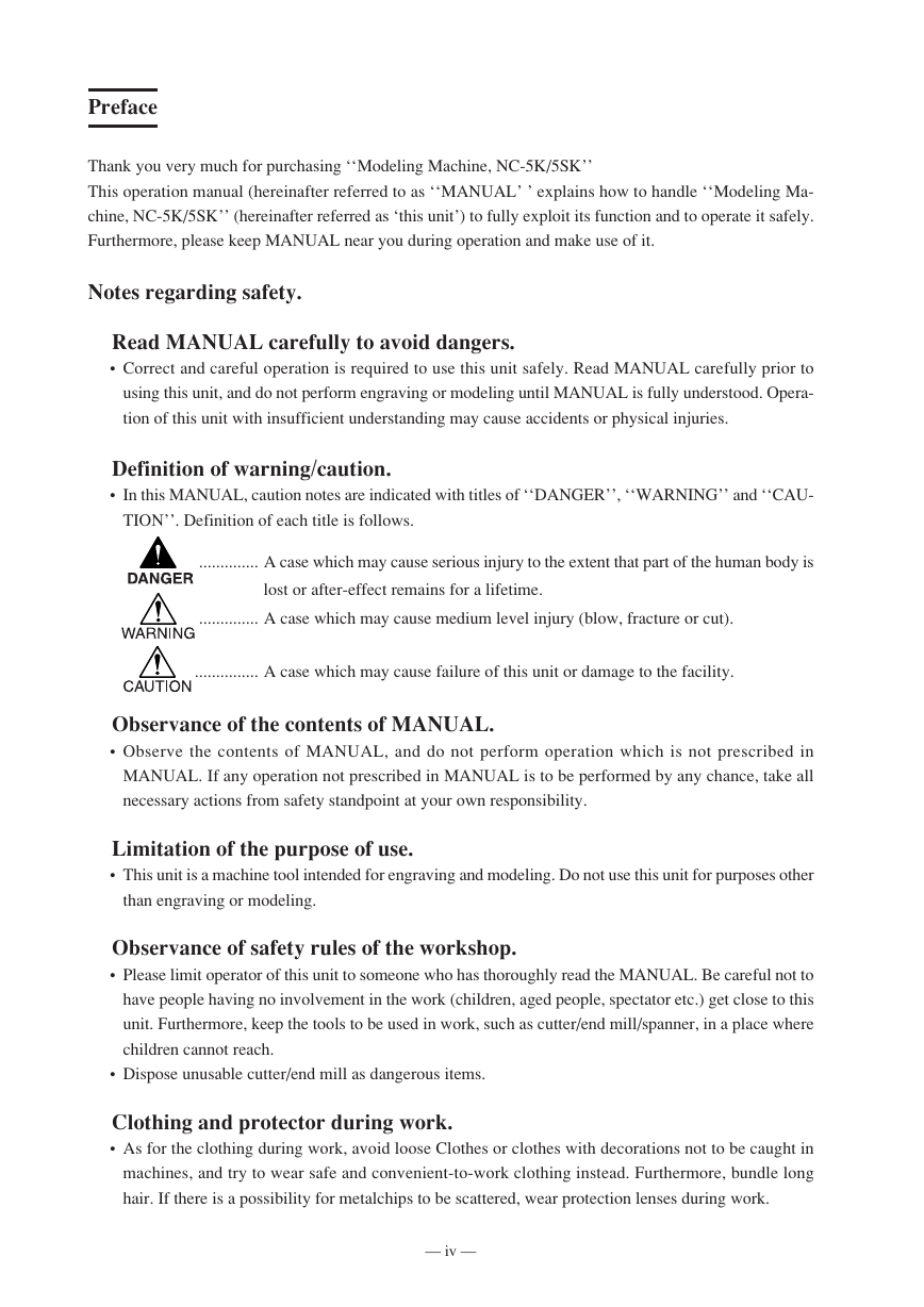
Preface Thank you very much for purchasing ‘‘Modeling Machine, NC-5K/5SK’’ This operation manual (hereinafter referred to as ‘‘MANUAL’ ’ explains how to handle ‘‘Modeling Ma- chine, NC-5K/5SK’’ (hereinafter referred as ‘this unit’) to fully exploit its function and to operate it safely. Furthermore, please keep MANUAL near you during operation and make use of it. Notes regarding safety. Read MANUAL carefully to avoid dangers. • Correct and careful operation is required to use this unit safely. Read MANUAL carefully prior to using this unit, and do not perform engraving or modeling until MANUAL is fully understood. Opera- tion of this unit with insufficient understanding may cause accidents or physical injuries. Definition of warning/caution. • In this MANUAL, caution notes are indicated with titles of ‘‘DANGER’’, ‘‘WARNING’’ and ‘‘CAU- TION’’. Definition of each title is follows. .............. A case which may cause serious injury to the extent that part of the human body is lost or after-effect remains for a lifetime. .............. A case which may cause medium level injury (blow, fracture or cut). ............... A case which may cause failure of this unit or damage to the facility. Observance of the contents of MANUAL. • Observe the contents of MANUAL, and do not perform operation which is not prescribed in MANUAL. If any operation not prescribed in MANUAL is to be performed by any chance, take all necessary actions from safety standpoint at your own responsibility. Limitation of the purpose of use. • This unit is a machine tool intended for engraving and modeling. Do not use this unit for purposes other than engraving or modeling. Observance of safety rules of the workshop. • Please limit operator of this unit to someone who has thoroughly read the MANUAL. Be careful not to have people having no involvement in the work (children, aged people, spectator etc.) get close to this unit. Furthermore, keep the tools to be used in work, such as cutter/end mill/spanner, in a place where children cannot reach. • Dispose unusable cutter/end mill as dangerous items. Clothing and protector during work. • As for the clothing during work, avoid loose Clothes or clothes with decorations not to be caught in machines, and try to wear safe and convenient-to-work clothing instead. Furthermore, bundle long hair. If there is a possibility for metalchips to be scattered, wear protection lenses during work. — iv —
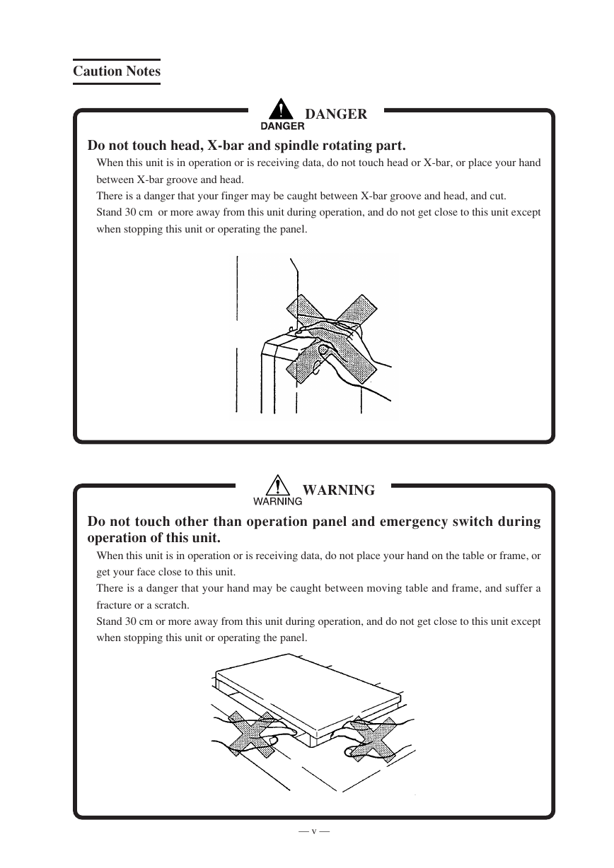
Caution Notes DANGER Do not touch head, X-bar and spindle rotating part. When this unit is in operation or is receiving data, do not touch head or X-bar, or place your hand between X-bar groove and head. There is a danger that your finger may be caught between X-bar groove and head, and cut. Stand 30 cm or more away from this unit during operation, and do not get close to this unit except when stopping this unit or operating the panel. WARNING Do not touch other than operation panel and emergency switch during operation of this unit. When this unit is in operation or is receiving data, do not place your hand on the table or frame, or get your face close to this unit. There is a danger that your hand may be caught between moving table and frame, and suffer a fracture or a scratch. Stand 30 cm or more away from this unit during operation, and do not get close to this unit except when stopping this unit or operating the panel. — v —
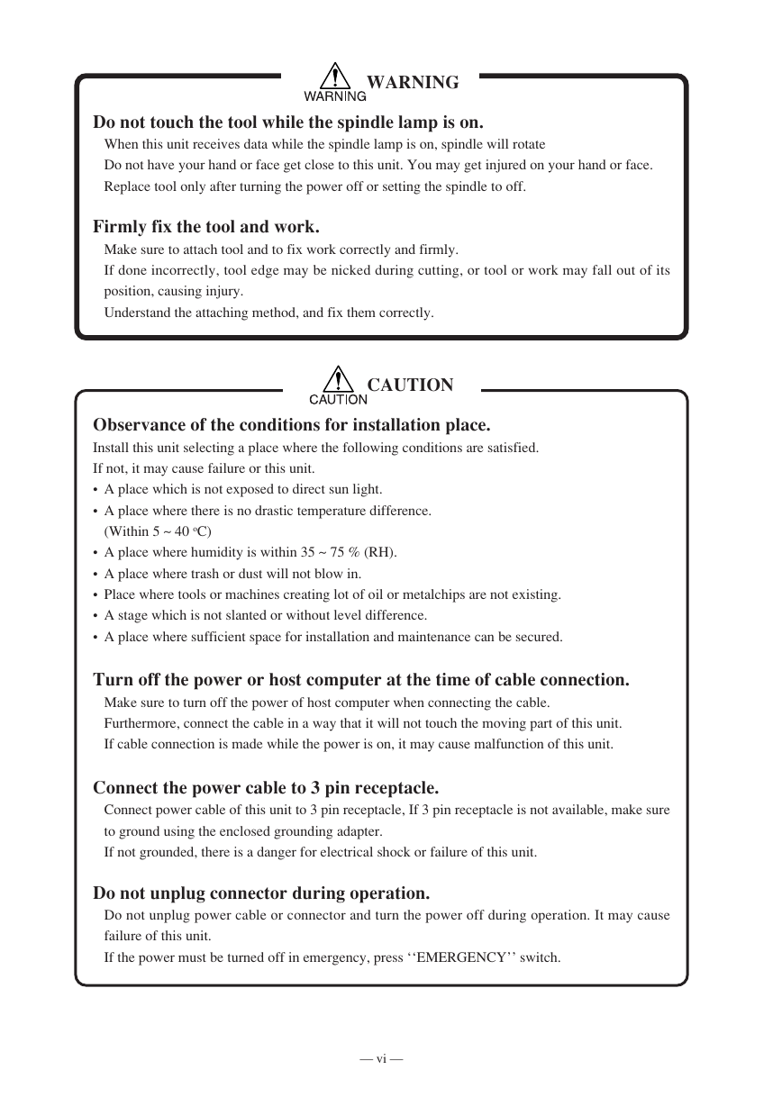
WARNING Do not touch the tool while the spindle lamp is on. When this unit receives data while the spindle lamp is on, spindle will rotate Do not have your hand or face get close to this unit. You may get injured on your hand or face. Replace tool only after turning the power off or setting the spindle to off. Firmly fix the tool and work. Make sure to attach tool and to fix work correctly and firmly. If done incorrectly, tool edge may be nicked during cutting, or tool or work may fall out of its position, causing injury. Understand the attaching method, and fix them correctly. CAUTION Observance of the conditions for installation place. Install this unit selecting a place where the following conditions are satisfied. If not, it may cause failure or this unit. • A place which is not exposed to direct sun light. • A place where there is no drastic temperature difference. (Within 5 ~ 40 oC) • A place where humidity is within 35 ~ 75 % (RH). • A place where trash or dust will not blow in. • Place where tools or machines creating lot of oil or metalchips are not existing. • A stage which is not slanted or without level difference. • A place where sufficient space for installation and maintenance can be secured. Turn off the power or host computer at the time of cable connection. Make sure to turn off the power of host computer when connecting the cable. Furthermore, connect the cable in a way that it will not touch the moving part of this unit. If cable connection is made while the power is on, it may cause malfunction of this unit. Connect the power cable to 3 pin receptacle. Connect power cable of this unit to 3 pin receptacle, If 3 pin receptacle is not available, make sure to ground using the enclosed grounding adapter. If not grounded, there is a danger for electrical shock or failure of this unit. Do not unplug connector during operation. Do not unplug power cable or connector and turn the power off during operation. It may cause failure of this unit. If the power must be turned off in emergency, press ‘‘EMERGENCY’’ switch. — vi —
分享到:
收藏