logo资料库

库卡机器人编程手册.pdf

第1页 / 共499页
第2页 / 共499页
第3页 / 共499页
第4页 / 共499页
第5页 / 共499页
第6页 / 共499页
第7页 / 共499页
第8页 / 共499页
资料共499页,剩余部分请下载后查看
KUKA System Software 8.3
1 Introduction
1.1 Target group
1.2 Industrial robot documentation
1.3 Representation of warnings and notes
1.4 Trademarks
2 Product description
2.1 Overview of the industrial robot
2.2 Overview of KUKA System Software (KSS)
2.3 System requirements
2.4 Intended use of the KUKA System Software
2.5 KUKA USB sticks
3 Safety
3.1 General
3.1.1 Liability
3.1.2 Intended use of the industrial robot
3.1.3 EC declaration of conformity and declaration of incorporation
3.1.4 Terms used
3.2 Personnel
3.3 Workspace, safety zone and danger zone
3.3.1 Determining stopping distances
3.4 Triggers for stop reactions
3.5 Safety functions
3.5.1 Overview of the safety functions
3.5.2 Safety controller
3.5.3 Selecting the operating mode
3.5.4 “Operator safety” signal
3.5.5 EMERGENCY STOP device
3.5.6 Logging off from the higher-level safety controller
3.5.7 External EMERGENCY STOP device
3.5.8 Enabling device
3.5.9 External enabling device
3.5.10 External safe operational stop
3.5.11 External safety stop 1 and external safety stop 2
3.5.12 Velocity monitoring in T1
3.6 Additional protective equipment
3.6.1 Jog mode
3.6.2 Software limit switches
3.6.3 Mechanical end stops
3.6.4 Mechanical axis range limitation (optional)
3.6.5 Axis range monitoring (optional)
3.6.6 Options for moving the manipulator without drive energy
3.6.7 Labeling on the industrial robot
3.6.8 External safeguards
3.7 Overview of operating modes and safety functions
3.8 Safety measures
3.8.1 General safety measures
3.8.2 Transportation
3.8.3 Start-up and recommissioning
3.8.3.1 Checking machine data and safety configuration
3.8.3.2 Start-up mode
3.8.4 Manual mode
3.8.5 Simulation
3.8.6 Automatic mode
3.8.7 Maintenance and repair
3.8.8 Decommissioning, storage and disposal
3.8.9 Safety measures for “single point of control”
3.9 Applied norms and regulations
4 Operation
4.1 KUKA smartPAD teach pendant
4.1.1 Front view
4.1.2 Rear view
4.1.3 Disconnecting and connecting the smartPAD
4.2 KUKA smartHMI user interface
4.2.1 Keypad
4.2.2 Status bar
4.2.3 Drives status indicator and Motion conditions window
4.2.4 Minimizing KUKA smartHMI (displaying Windows interface)
4.3 Switching on the robot controller and starting the KSS
4.4 Calling the main menu
4.5 Defining the start type for KSS
4.6 Exiting or restarting KSS
4.6.1 Shutting down after power failure
4.7 Switching drives on/off
4.8 Switching the robot controller off
4.9 Setting the user interface language
4.10 Online documentation and online help
4.10.1 Calling online documentation
4.10.2 Calling online help
4.11 Changing user group
4.12 Changing operating mode
4.13 Coordinate systems
4.14 Jogging the robot
4.14.1 “Jog options” window
4.14.1.1 “General” tab
4.14.1.2 “Keys” tab
4.14.1.3 “Mouse” tab
4.14.1.4 “KCP pos.” tab
4.14.1.5 “Cur. tool/base” tab
4.14.2 Activating the jog mode
4.14.3 Setting the jog override (HOV)
4.14.4 Selecting the tool and base
4.14.5 Axis-specific jogging with the jog keys
4.14.6 Cartesian jogging with the jog keys
4.14.7 Configuring the Space Mouse
4.14.8 Defining the alignment of the Space Mouse
4.14.9 Cartesian jogging with the Space Mouse
4.14.10 Incremental jogging
4.15 Jogging external axes
4.16 Bypassing workspace monitoring
4.17 Display functions
4.17.1 Measuring and displaying energy consumption
4.17.2 Displaying the actual position
4.17.3 Displaying digital inputs/outputs
4.17.4 Displaying analog inputs/outputs
4.17.5 Displaying inputs/outputs for Automatic External
4.17.6 Displaying and modifying the value of a variable
4.17.7 Displaying the state of a variable
4.17.8 Displaying the variable overview and modifying variables
4.17.9 Displaying cyclical flags
4.17.10 Displaying flags
4.17.11 Displaying counters
4.17.12 Displaying timers
4.17.13 Displaying calibration data
4.17.14 Displaying information about the robot and robot controller
4.17.15 Displaying/editing robot data
4.18 Resetting safe input/output errors
4.19 Displaying the battery state
5 Start-up and recommissioning
5.1 Start-up wizard
5.2 Checking the machine data
5.3 Modifying the machine data configuration
5.4 Defining hardware options
5.5 Changing the safety ID of the PROFINET device
5.6 Jogging the robot without a higher-level safety controller
5.7 Checking the activation of the positionally accurate robot model
5.8 Activating palletizing mode
5.9 Mastering
5.9.1 Mastering methods
5.9.2 Moving axes to the pre-mastering position using mastering marks
5.9.3 Moving axes to the pre-mastering position using the probe
5.9.4 Mastering LEDs
5.9.5 Mastering with the SEMD
5.9.5.1 First mastering (with SEMD)
5.9.5.2 Teach offset (with SEMD)
5.9.5.3 Check load mastering with offset (with SEMD)
5.9.6 Mastering with the dial gauge
5.9.7 Mastering external axes
5.9.8 Reference mastering
5.9.9 Mastering with the MEMD and mark
5.9.9.1 Moving A6 to the mastering position (with line mark)
5.9.9.2 First mastering (with MEMD)
5.9.9.3 Teach offset (with MEMD)
5.9.9.4 Check load mastering with offset (with MEMD)
5.9.10 Manually unmastering axes
5.10 Modifying software limit switches
5.11 Calibration
5.11.1 Defining the tool direction
5.11.2 Tool calibration
5.11.2.1 TCP calibration: XYZ 4-point method
5.11.2.2 TCP calibration: XYZ Reference method
5.11.2.3 Defining the orientation: ABC World method
5.11.2.4 Defining the orientation: ABC 2-point method
5.11.2.5 Numeric input
5.11.3 Base calibration
5.11.3.1 Base calibration: 3-point method
5.11.3.2 Base calibration: indirect method
5.11.3.3 Entering the base numerically
5.11.4 Fixed tool calibration
5.11.4.1 Calibrating an external TCP
5.11.4.2 Entering the external TCP numerically
5.11.4.3 Workpiece calibration: direct method
5.11.4.4 Workpiece calibration: indirect method
5.11.5 Renaming the tool/base
5.11.6 Linear unit
5.11.6.1 Checking whether the linear unit needs to be calibrated
5.11.6.2 Calibrating the linear unit
5.11.6.3 Entering the linear unit numerically
5.11.7 Calibrating an external kinematic system
5.11.7.1 Calibrating the root point
5.11.7.2 Entering the root point numerically
5.11.7.3 Calibrating a workpiece base
5.11.7.4 Entering the workpiece base numerically
5.11.7.5 Calibrating an external tool
5.11.7.6 Entering the external tool numerically
5.12 Load data
5.12.1 Checking loads with KUKA.Load
5.12.2 Calculating payloads with KUKA.LoadDataDetermination
5.12.3 Entering payload data
5.12.4 Entering supplementary load data
5.12.5 Online load data check (OLDC)
5.13 Exporting/importing long texts
5.14 Maintenance handbook
5.14.1 Logging maintenance
5.14.2 Displaying a maintenance log
6 Configuration
6.1 Configuring the KUKA Line Interface (KLI)
6.1.1 Configuring the Windows interface (without field bus)
6.1.2 Configuring the field bus interface and creating the Windows interface
6.1.3 Displaying ports of the Windows interface or enabling an additional port
6.1.4 Displaying or modifying filters
6.1.5 Displaying the subnet configuration of the robot controller
6.1.6 Error display in the Address and Subnet boxes
6.2 Reconfiguring the I/O driver
6.3 Configuring safe axis monitoring functions
6.3.1 Parameter Braking time
6.4 Checking safe axis monitoring functions
6.5 Checking the safety configuration of the robot controller
6.6 Checksum of the safety configuration
6.7 Exporting the safety configuration (XML export)
6.8 Configuring the variable overview
6.9 Changing the password
6.10 Energy saving mode ($ECO_LEVEL)
6.11 Configuring workspaces
6.11.1 Configuring Cartesian workspaces
6.11.2 Configuring axis-specific workspaces
6.11.3 Mode for workspaces
6.12 Defining limits for reteaching
6.13 Warm-up
6.13.1 Warm-up sequence
6.13.2 Configuring warm-up
6.14 Collision detection
6.14.1 Calculating the tolerance range and activating collision detection
6.14.2 Defining an offset for the tolerance range
6.14.3 Option window “Collision detection”
6.14.4 Editing the program tm_useraction
6.14.5 Torque monitoring
6.14.5.1 Determining values for torque monitoring
6.14.5.2 Programming torque monitoring
6.15 Defining calibration tolerances
6.16 Configuring backward motion
6.17 Configuring Automatic External
6.17.1 Configuring CELL.SRC
6.17.2 Configuring Automatic External inputs/outputs
6.17.2.1 Automatic External inputs
6.17.2.2 Odd / even parity
6.17.2.3 Automatic External outputs
6.17.3 Transmitting error numbers to the higher-level controller
6.17.4 Signal diagrams
6.18 Torque mode
6.18.1 Overview of torque mode
6.18.1.1 Using torque mode
6.18.1.2 Robot program example: setting A1 to “soft” in both directions
6.18.2 Activating torque mode: SET_TORQUE_LIMITS()
6.18.3 Deactivating torque mode: RESET_TORQUE_LIMITS()
6.18.4 Interpreter specifics
6.18.5 Diagnostic variables for torque mode
6.18.5.1 $TORQUE_AXIS_ACT
6.18.5.2 $TORQUE_AXIS_MAX_0
6.18.5.3 $TORQUE_AXIS_MAX
6.18.5.4 $TORQUE_AXIS_LIMITS
6.18.5.5 $HOLDING_TORQUE
6.18.5.6 Comparison: $TORQUE_AXIS_ACT and $HOLDING_TORQUE
6.18.6 Other examples
6.18.6.1 Robot program: setting axis to “soft” in both directions
6.18.6.2 Robot program: avoiding damage in the event of collisions
6.18.6.3 Robot program: torque mode in the interrupt
6.18.6.4 Robot program: servo gun builds up pressure
6.18.6.5 Submit program: servo gun builds up pressure
6.19 Event planner
6.19.1 Configuring a data comparison
6.19.2 Configuring T1 and T2 Consistency, AUT and EXT Consistency
6.19.3 Configuring Logic Consistency
6.20 Brake test
6.20.1 Overview of the brake test
6.20.2 Activating the brake test
6.20.3 Programs for the brake test
6.20.4 Configuring input and output signals for the brake test
6.20.4.1 Signal diagram of the brake test – examples
6.20.5 Teaching positions for the brake test
6.20.6 Performing a manual brake test
6.20.7 Checking that the brake test is functioning correctly
7 Program and project management
7.1 Creating a new program
7.2 Creating a new folder
7.3 Renaming a file or folder
7.4 Navigator file manager
7.4.1 Selecting filters
7.4.2 Displaying or modifying properties of files and folders
7.5 Selecting or opening a program
7.5.1 Selecting and deselecting a program
7.5.2 Opening a program
7.5.3 Toggling between the Navigator and the program
7.6 Structure of a KRL program
7.6.1 HOME position
7.7 Displaying/hiding program sections
7.7.1 Displaying/hiding the DEF line
7.7.2 Activating detail view
7.7.3 Activating/deactivating the line break function
7.7.4 Displaying Folds
7.8 Editing programs
7.8.1 Inserting a comment or stamp
7.8.2 Deleting program lines
7.8.3 Creating folds
7.8.4 Additional editing functions
7.9 Printing a program
7.10 Archiving and restoring data
7.10.1 Archiving overview
7.10.2 Archiving to a USB stick
7.10.3 Archiving on the network
7.10.4 Archiving the logbook
7.10.5 Restoring data
7.11 Project management
7.11.1 Pinning a project on the robot controller
7.11.2 Activating a project
7.11.3 Project management window
7.12 Backup Manager
7.12.1 Overview of Backup Manager
7.12.2 Backing up projects, option packages and RDC data manually
7.12.3 Manually restoring projects and option packages
7.12.4 Restoring RDC data manually
7.12.5 Configuring Backup Manager
7.12.5.1 “Backup configuration” tab
7.12.5.2 “Signal interface” tab
8 Program execution
8.1 Selecting the program run mode
8.2 Program run modes
8.3 Advance run
8.4 Block pointer
8.5 Setting the program override (POV)
8.6 Robot interpreter status indicator
8.7 Starting a program forwards (manual)
8.8 Starting a program forwards (automatic)
8.9 Carrying out a block selection
8.10 Resetting a program
8.11 Starting Automatic External mode
8.12 Backward motion using the Start backwards key
8.12.1 Executing motions backwards (using the “Start backwards” key)
8.12.2 Functional principle and characteristics of backward motion
8.12.2.1 Response in the case of subprograms
8.12.2.2 Approximate positioning response
8.12.2.3 Response in the case of weave motions
8.12.2.4 Switching from backwards to forwards
8.12.3 System variables with changed meaning
9 Basic principles of motion programming
9.1 Overview of motion types
9.2 Motion type PTP
9.3 Motion type LIN
9.4 Motion type CIRC
9.5 Approximate positioning
9.6 Orientation control LIN, CIRC
9.6.1 Combinations of $ORI_TYPE and $CIRC_TYPE
9.7 Spline motion type
9.7.1 Velocity profile for spline motions
9.7.2 Block selection with spline motions
9.7.3 Modifications to spline blocks
9.7.4 Approximation of spline motions
9.7.5 Replacing an approximated CP motion with a spline block
9.7.5.1 SLIN-SPL-SLIN transition
9.8 Orientation control for CP spline motions
9.8.1 SCIRC: reference system for the orientation control
9.8.2 SCIRC: orientation behavior
9.8.2.1 SCIRC: Orientation behavior – example: auxiliary point
9.8.2.2 SCIRC: Orientation behavior – example: end point
9.9 Circular angle
9.10 Status and Turn
9.10.1 Status
9.10.2 Turn
9.11 Singularities
10 Programming for user group “User” (inline forms)
10.1 Names in inline forms
10.2 Programming PTP, LIN and CIRC motions
10.2.1 Programming a PTP motion
10.2.2 Inline form “PTP”
10.2.3 Programming a LIN motion
10.2.4 Inline form “LIN”
10.2.5 Programming a CIRC motion
10.2.6 Inline form “CIRC”
10.2.7 Option window “Frames”
10.2.8 Option window “Motion parameters” (LIN, CIRC, PTP)
10.3 Programming spline motions
10.3.1 Programming tips for spline motions
10.3.2 Programming a spline block
10.3.2.1 Inline form for CP spline block
10.3.2.2 Inline form “PTP SPLINE block”
10.3.2.3 Option window “Frames” (CP and PTP spline block)
10.3.2.4 Option window “Motion parameters” (CP spline block)
10.3.2.5 Option window “Motion parameters” (PTP spline block)
10.3.3 Programming segments for a spline block
10.3.3.1 Programming an SPL or SLIN segment
10.3.3.2 Programming an SCIRC segment
10.3.3.3 Inline form for CP spline segment
10.3.3.4 Programming an SPTP segment
10.3.3.5 Inline form for SPTP segment
10.3.3.6 Option window “Frames” (CP and PTP spline segments)
10.3.3.7 Option window “Motion parameters” (CP spline segment)
10.3.3.8 Option window “Motion parameters” (SPTP)
10.3.3.9 Option window “Logic parameters”
10.3.3.10 Teaching the shift in space for logic parameters
10.3.4 Programming individual spline motions
10.3.4.1 Programming an individual SLIN motion
10.3.4.2 Inline form “SLIN”
10.3.4.3 Option window “Motion parameters” (SLIN)
10.3.4.4 Programming an individual SCIRC motion
10.3.4.5 Inline form “SCIRC”
10.3.4.6 Option window “Motion parameters” (SCIRC)
10.3.4.7 Programming an individual SPTP motion
10.3.4.8 Inline form “SPTP”
10.3.5 Conditional stop
10.3.5.1 Inline form “Spline Stop Condition”
10.3.5.2 Stop condition: example and braking characteristics
10.3.6 Constant velocity range in the CP spline block
10.3.6.1 Block selection to the constant velocity range
10.3.6.2 Maximum limits
10.4 Displaying the distance between points
10.5 Modifying programmed motions
10.5.1 Modifying motion parameters
10.5.2 Modifying blocks of motion parameters
10.5.3 Re-teaching a point
10.5.4 Transforming blocks of coordinates
10.5.4.1 “Axis mirroring” window
10.5.4.2 “Transform - Axis Specific” window
10.5.4.3 “Transform - Cartesian Base” window
10.6 Programming logic instructions
10.6.1 Inputs/outputs
10.6.2 Setting a digital output - OUT
10.6.3 Inline form “OUT”
10.6.4 Setting a pulse output - PULSE
10.6.5 Inline form “PULSE”
10.6.6 Setting an analog output - ANOUT
10.6.7 Inline form “ANOUT” (static)
10.6.8 Inline form “ANOUT” (dynamic)
10.6.9 Programming a wait time - WAIT
10.6.10 Inline form “WAIT”
10.6.11 Programming a signal-dependent wait function - WAITFOR
10.6.12 Inline form “WAITFOR”
10.6.13 Switching on the path - SYN OUT
10.6.14 Inline form “SYN OUT”, option “START/END”
10.6.15 Inline form “SYN OUT”, option “PATH”
10.6.16 Setting a pulse on the path - SYN PULSE
10.6.17 Inline form “SYN PULSE”
10.6.18 Modifying a logic instruction
11 Programming for user group “Expert” (KRL syntax)
11.1 Overview of KRL syntax
11.2 Symbols and fonts
11.3 Important KRL terms
11.3.1 SRC files and DAT files
11.3.2 Naming conventions and keywords
11.3.3 Data types
11.3.4 Areas of validity
11.3.4.1 Making subprograms, functions and interrupts available globally
11.3.4.2 Making variables, constants, signals and user data types available globally
11.3.5 Constants
11.4 Variables and declarations
11.4.1 DECL
11.4.2 ENUM
11.4.3 STRUC
11.5 Motion programming: PTP, LIN, CIRC
11.5.1 PTP
11.5.2 PTP_REL
11.5.3 LIN, CIRC
11.5.4 LIN_REL, CIRC_REL
11.5.5 Approximation parameters for PTP, LIN CIRC and …_REL
11.5.6 REL motions for infinitely rotating axes
11.6 Motion programming: spline
11.6.1 SPLINE ... ENDSPLINE
11.6.2 PTP_SPLINE ... ENDSPLINE
11.6.3 SLIN, SCIRC, SPL
11.6.4 SLIN_REL, SCIRC_REL, SPL_REL
11.6.5 SPTP
11.6.6 SPTP_REL
11.6.7 System variables for WITH
11.6.8 TIME_BLOCK
11.6.9 CONST_VEL
11.6.9.1 System variables for CONST_VEL
11.6.10 STOP WHEN PATH
11.6.11 $EX_AX_IGNORE
11.7 Program execution control
11.7.1 CONTINUE
11.7.2 EXIT
11.7.3 FOR ... TO ... ENDFOR
11.7.4 GOTO
11.7.5 HALT
11.7.6 IF ... THEN ... ENDIF
11.7.7 LOOP ... ENDLOOP
11.7.8 ON_ERROR_PROCEED
11.7.8.1 $ERR
11.7.8.2 Examples of $ERR, ON_ERROR_PROCEED and ERR_RAISE()
11.7.9 REPEAT ... UNTIL
11.7.10 SWITCH ... CASE ... ENDSWITCH
11.7.11 WAIT FOR …
11.7.12 WAIT SEC …
11.7.13 WHILE ... ENDWHILE
11.8 Inputs/outputs
11.8.1 ANIN
11.8.2 ANOUT
11.8.3 PULSE
11.8.4 SIGNAL
11.9 Subprograms and functions
11.9.1 Calling a subprogram
11.9.2 Calling a function
11.9.3 DEFFCT ... ENDFCT
11.9.4 RETURN
11.9.5 Transferring parameters to a subprogram or function
11.9.6 Transferring a parameter to a different data type
11.10 Interrupt programming
11.10.1 BRAKE
11.10.2 INTERRUPT ... DECL ... WHEN ... DO
11.10.3 INTERRUPT
11.10.4 RESUME
11.11 Path-related switching actions (=Trigger)
11.11.1 TRIGGER WHEN DISTANCE
11.11.2 TRIGGER WHEN PATH
11.11.2.1 Reference point for approximate positioning – overview
11.11.2.2 Reference point for homogenous approximate positioning
11.11.2.3 Reference point for mixed approximate positioning (spline)
11.11.2.4 Reference point for mixed approximate positioning (LIN/CIRC/PTP)
11.11.3 Constraints for functions in the trigger
11.11.4 Useful system variables for working with PATH triggers
11.11.4.1 $DIST_NEXT
11.11.4.2 $DIST_LAST
11.12 Communication
11.13 Operators
11.13.1 Arithmetic operators
11.13.2 Geometric operator
11.13.2.1 Sequence of the operands
11.13.2.2 Example of a double operation
11.13.3 Relational operators
11.13.4 Logic operators
11.13.5 Bit operators
11.13.6 Priority of the operators
11.14 System functions
11.14.1 DELETE_BACKWARD_BUFFER()
11.14.2 ROB_STOP() and ROB_STOP_RELEASE()
11.14.3 SET_BRAKE_DELAY()
11.14.4 VARSTATE()
11.15 Editing string variables
11.15.1 String variable length in the declaration
11.15.2 String variable length after initialization
11.15.3 Deleting the contents of a string variable
11.15.4 Extending a string variable
11.15.5 Searching a string variable
11.15.6 Comparing the contents of string variables
11.15.7 Copying a string variable
12 Submit interpreter
12.1 Function of the submit interpreter
12.2 Manually stopping or deselecting the Submit interpreter
12.3 Manually starting the Submit interpreter
12.4 Editing the program SPS.SUB
12.5 Creating a new SUB program
12.6 Programming
13 Diagnosis
13.1 Logbook
13.1.1 Displaying the logbook
13.1.2 “Log” tab
13.1.3 “Filter” tab
13.1.4 Configuring the logbook
13.2 Displaying the caller stack
13.3 Displaying interrupts
13.4 Displaying diagnostic data about the kernel system
13.5 Automatically compressing data for error analysis (KrcDiag)
14 Installation
14.1 System requirements
14.2 Installing Windows and the KUKA System Software (KSS) (from image)
14.3 Changing the computer name
14.4 Installing additional software
14.5 KSS update
14.5.1 Update from USB stick
14.5.2 Update from the network
15 KUKA Service
15.1 Requesting support
15.2 KUKA Customer Support
Index
KUKA System Software KUKA Roboter GmbH KUKA System Software 8.3 Operating and Programming Instructions for System Integrators KUKA System Software 8.3 Issued: 11.05.2016 Version: KSS 8.3 SI V5
KUKA System Software 8.3 © Copyright 2016 KUKA Roboter GmbH Zugspitzstraße 140 D-86165 Augsburg Germany This documentation or excerpts therefrom may not be reproduced or disclosed to third parties without the express permission of KUKA Roboter GmbH. Other functions not described in this documentation may be operable in the controller. The user has no claims to these functions, however, in the case of a replacement or service work. We have checked the content of this documentation for conformity with the hardware and software described. Nevertheless, discrepancies cannot be precluded, for which reason we are not able to guarantee total conformity. The information in this documentation is checked on a regular basis, how- ever, and necessary corrections will be incorporated in the subsequent edition. Subject to technical alterations without an effect on the function. Translation of the original documentation KIM-PS5-DOC Publication: Book structure: Version: Pub KSS 8.3 SI (PDF) en KSS 8.3 SI V5.5 KSS 8.3 SI V5 2 / 499 Issued: 11.05.2016 Version: KSS 8.3 SI V5
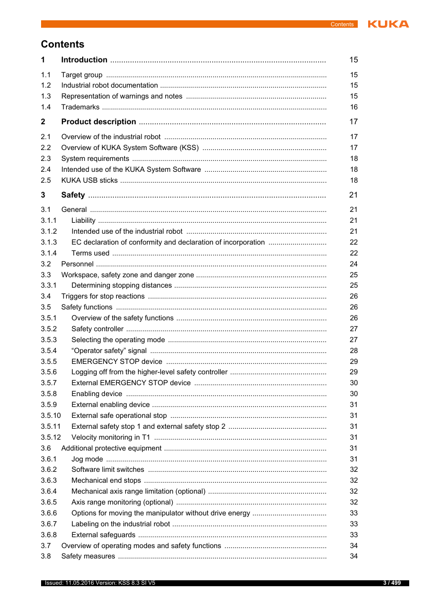
Contents 1 Introduction .................................................................................................. Target group .............................................................................................................. 1.1 Industrial robot documentation ................................................................................... 1.2 Representation of warnings and notes ...................................................................... 1.3 Trademarks ................................................................................................................ 1.4 Product description ..................................................................................... 2 2.1 Overview of the industrial robot ................................................................................. 2.2 Overview of KUKA System Software (KSS) .............................................................. System requirements ................................................................................................. 2.3 2.4 Intended use of the KUKA System Software ............................................................. KUKA USB sticks ....................................................................................................... 2.5 3 Safety ............................................................................................................ 3.1 General ...................................................................................................................... Liability .................................................................................................................. 3.1.1 Intended use of the industrial robot ...................................................................... 3.1.2 3.1.3 EC declaration of conformity and declaration of incorporation ............................. Terms used ........................................................................................................... 3.1.4 3.2 Personnel ................................................................................................................... 3.3 Workspace, safety zone and danger zone ................................................................. Determining stopping distances ............................................................................ 3.3.1 Triggers for stop reactions ......................................................................................... 3.4 3.5 Safety functions ......................................................................................................... Overview of the safety functions ........................................................................... 3.5.1 Safety controller .................................................................................................... 3.5.2 Selecting the operating mode ............................................................................... 3.5.3 3.5.4 “Operator safety” signal ........................................................................................ EMERGENCY STOP device ................................................................................ 3.5.5 Logging off from the higher-level safety controller ................................................ 3.5.6 3.5.7 External EMERGENCY STOP device .................................................................. Enabling device .................................................................................................... 3.5.8 External enabling device ....................................................................................... 3.5.9 3.5.10 External safe operational stop .............................................................................. External safety stop 1 and external safety stop 2 ................................................. 3.5.11 Velocity monitoring in T1 ...................................................................................... 3.5.12 Additional protective equipment ................................................................................. 3.6 3.6.1 Jog mode .............................................................................................................. Software limit switches ......................................................................................... 3.6.2 Mechanical end stops ........................................................................................... 3.6.3 3.6.4 Mechanical axis range limitation (optional) ........................................................... Axis range monitoring (optional) ........................................................................... 3.6.5 Options for moving the manipulator without drive energy ..................................... 3.6.6 3.6.7 Labeling on the industrial robot ............................................................................. 3.6.8 External safeguards .............................................................................................. 3.7 Overview of operating modes and safety functions ................................................... 3.8 Safety measures ........................................................................................................ Contents 15 15 15 15 16 17 17 17 18 18 18 21 21 21 21 22 22 24 25 25 26 26 26 27 27 28 29 29 30 30 31 31 31 31 31 31 32 32 32 32 33 33 33 34 34 Issued: 11.05.2016 Version: KSS 8.3 SI V5 3 / 499
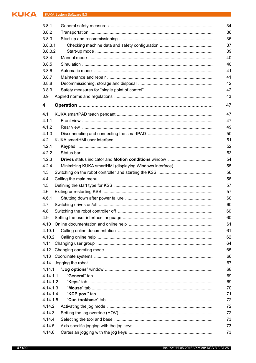
KUKA System Software 8.3 General safety measures ..................................................................................... 3.8.1 Transportation ...................................................................................................... 3.8.2 Start-up and recommissioning .............................................................................. 3.8.3 Checking machine data and safety configuration ............................................ 3.8.3.1 Start-up mode .................................................................................................. 3.8.3.2 Manual mode ........................................................................................................ 3.8.4 Simulation ............................................................................................................. 3.8.5 Automatic mode ................................................................................................... 3.8.6 Maintenance and repair ........................................................................................ 3.8.7 Decommissioning, storage and disposal .............................................................. 3.8.8 Safety measures for “single point of control” ........................................................ 3.8.9 Applied norms and regulations .................................................................................. 3.9 Operation ...................................................................................................... 4 KUKA smartPAD teach pendant ................................................................................ 4.1 Front view ............................................................................................................. 4.1.1 Rear view ............................................................................................................. 4.1.2 Disconnecting and connecting the smartPAD ...................................................... 4.1.3 KUKA smartHMI user interface ................................................................................. 4.2 Keypad ................................................................................................................. 4.2.1 Status bar ............................................................................................................. 4.2.2 Drives status indicator and Motion conditions window ..................................... 4.2.3 Minimizing KUKA smartHMI (displaying Windows interface) ............................... 4.2.4 Switching on the robot controller and starting the KSS ............................................. 4.3 Calling the main menu ............................................................................................... 4.4 Defining the start type for KSS .................................................................................. 4.5 Exiting or restarting KSS ........................................................................................... 4.6 Shutting down after power failure ......................................................................... 4.6.1 Switching drives on/off ............................................................................................... 4.7 Switching the robot controller off ............................................................................... 4.8 4.9 Setting the user interface language ........................................................................... 4.10 Online documentation and online help ...................................................................... 4.10.1 Calling online documentation ............................................................................... 4.10.2 Calling online help ................................................................................................ 4.11 Changing user group ................................................................................................. 4.12 Changing operating mode ......................................................................................... 4.13 Coordinate systems ................................................................................................... 4.14 Jogging the robot ....................................................................................................... “Jog options” window .......................................................................................... 4.14.1 “General” tab ................................................................................................... 4.14.1.1 “Keys” tab ....................................................................................................... 4.14.1.2 “Mouse” tab ..................................................................................................... 4.14.1.3 “KCP pos.” tab ................................................................................................ 4.14.1.4 “Cur. tool/base” tab ........................................................................................ 4.14.1.5 Activating the jog mode ........................................................................................ 4.14.2 4.14.3 Setting the jog override (HOV) ............................................................................. Selecting the tool and base .................................................................................. 4.14.4 Axis-specific jogging with the jog keys ................................................................. 4.14.5 4.14.6 Cartesian jogging with the jog keys ...................................................................... 34 36 36 37 39 40 40 41 41 42 42 43 47 47 47 49 50 51 52 53 54 55 56 56 57 57 60 60 60 60 61 61 62 64 65 66 67 68 69 69 70 71 72 72 72 73 73 73 4 / 499 Issued: 11.05.2016 Version: KSS 8.3 SI V5
Configuring the Space Mouse .............................................................................. 4.14.7 Defining the alignment of the Space Mouse ......................................................... 4.14.8 4.14.9 Cartesian jogging with the Space Mouse ............................................................. 4.14.10 Incremental jogging .............................................................................................. 4.15 Jogging external axes ................................................................................................ 4.16 Bypassing workspace monitoring .............................................................................. 4.17 Display functions ........................................................................................................ 4.17.1 Measuring and displaying energy consumption .................................................... 4.17.2 Displaying the actual position ............................................................................... Displaying digital inputs/outputs ........................................................................... 4.17.3 Displaying analog inputs/outputs .......................................................................... 4.17.4 4.17.5 Displaying inputs/outputs for Automatic External ................................................. Displaying and modifying the value of a variable .................................................. 4.17.6 Displaying the state of a variable .......................................................................... 4.17.7 4.17.8 Displaying the variable overview and modifying variables .................................... 4.17.9 Displaying cyclical flags ........................................................................................ 4.17.10 Displaying flags ..................................................................................................... 4.17.11 Displaying counters .............................................................................................. 4.17.12 Displaying timers .................................................................................................. 4.17.13 Displaying calibration data .................................................................................... 4.17.14 Displaying information about the robot and robot controller ................................. 4.17.15 Displaying/editing robot data ................................................................................ 4.18 Resetting safe input/output errors .............................................................................. 4.19 Displaying the battery state ........................................................................................ 5 Start-up and recommissioning ................................................................... Start-up wizard ........................................................................................................... 5.1 5.2 Checking the machine data ....................................................................................... 5.3 Modifying the machine data configuration ................................................................. Defining hardware options ......................................................................................... 5.4 Changing the safety ID of the PROFINET device ...................................................... 5.5 Jogging the robot without a higher-level safety controller .......................................... 5.6 5.7 Checking the activation of the positionally accurate robot model .............................. 5.8 Activating palletizing mode ........................................................................................ 5.9 Mastering ................................................................................................................... 5.9.1 Mastering methods ............................................................................................... Moving axes to the pre-mastering position using mastering marks ...................... 5.9.2 Moving axes to the pre-mastering position using the probe ................................. 5.9.3 5.9.4 Mastering LEDs .................................................................................................... Mastering with the SEMD ..................................................................................... 5.9.5 First mastering (with SEMD) ............................................................................ 5.9.5.1 Teach offset (with SEMD) ................................................................................ 5.9.5.2 5.9.5.3 Check load mastering with offset (with SEMD) ................................................ Mastering with the dial gauge ............................................................................... 5.9.6 Mastering external axes ........................................................................................ 5.9.7 5.9.8 Reference mastering ............................................................................................ Mastering with the MEMD and mark ..................................................................... 5.9.9 Moving A6 to the mastering position (with line mark) ...................................... 5.9.9.1 5.9.9.2 First mastering (with MEMD) ........................................................................... Contents 74 76 77 77 78 78 79 79 81 81 83 83 84 85 86 87 88 89 90 91 92 92 94 95 97 97 97 98 98 99 100 101 102 103 104 105 107 108 109 109 112 113 114 115 115 116 117 118 Issued: 11.05.2016 Version: KSS 8.3 SI V5 5 / 499
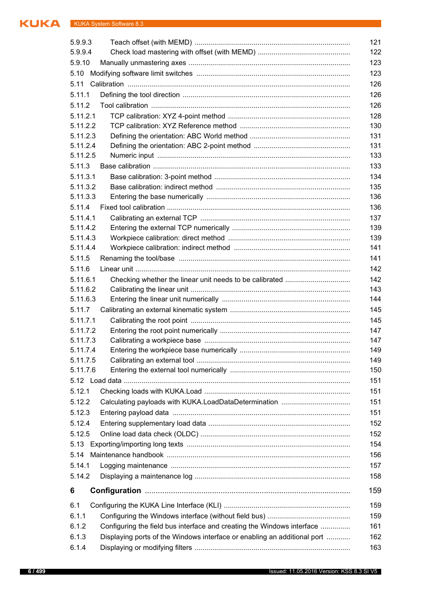
KUKA System Software 8.3 Teach offset (with MEMD) ............................................................................... 5.9.9.3 Check load mastering with offset (with MEMD) ............................................... 5.9.9.4 5.9.10 Manually unmastering axes .................................................................................. 5.10 Modifying software limit switches .............................................................................. 5.11 Calibration ................................................................................................................. 5.11.1 Defining the tool direction ..................................................................................... Tool calibration ..................................................................................................... 5.11.2 TCP calibration: XYZ 4-point method .............................................................. 5.11.2.1 5.11.2.2 TCP calibration: XYZ Reference method ........................................................ Defining the orientation: ABC World method ................................................... 5.11.2.3 Defining the orientation: ABC 2-point method ................................................. 5.11.2.4 5.11.2.5 Numeric input .................................................................................................. Base calibration .................................................................................................... 5.11.3 Base calibration: 3-point method ..................................................................... 5.11.3.1 Base calibration: indirect method .................................................................... 5.11.3.2 5.11.3.3 Entering the base numerically ......................................................................... Fixed tool calibration ............................................................................................. 5.11.4 Calibrating an external TCP ............................................................................ 5.11.4.1 Entering the external TCP numerically ............................................................ 5.11.4.2 5.11.4.3 Workpiece calibration: direct method .............................................................. 5.11.4.4 Workpiece calibration: indirect method ........................................................... Renaming the tool/base ....................................................................................... 5.11.5 5.11.6 Linear unit ............................................................................................................. Checking whether the linear unit needs to be calibrated ................................. 5.11.6.1 Calibrating the linear unit ................................................................................. 5.11.6.2 5.11.6.3 Entering the linear unit numerically ................................................................. Calibrating an external kinematic system ............................................................. 5.11.7 Calibrating the root point ................................................................................. 5.11.7.1 Entering the root point numerically .................................................................. 5.11.7.2 5.11.7.3 Calibrating a workpiece base .......................................................................... Entering the workpiece base numerically ........................................................ 5.11.7.4 Calibrating an external tool .............................................................................. 5.11.7.5 5.11.7.6 Entering the external tool numerically ............................................................. 5.12 Load data ................................................................................................................... Checking loads with KUKA.Load .......................................................................... 5.12.1 Calculating payloads with KUKA.LoadDataDetermination ................................... 5.12.2 5.12.3 Entering payload data .......................................................................................... 5.12.4 Entering supplementary load data ........................................................................ 5.12.5 Online load data check (OLDC) ............................................................................ 5.13 Exporting/importing long texts ................................................................................... 5.14 Maintenance handbook ............................................................................................. Logging maintenance ........................................................................................... 5.14.1 5.14.2 Displaying a maintenance log ............................................................................... Configuration ............................................................................................... 6 Configuring the KUKA Line Interface (KLI) ................................................................ 6.1 6.1.1 Configuring the Windows interface (without field bus) .......................................... Configuring the field bus interface and creating the Windows interface ............... 6.1.2 Displaying ports of the Windows interface or enabling an additional port ............ 6.1.3 6.1.4 Displaying or modifying filters ............................................................................... 121 122 123 123 126 126 126 128 130 131 131 133 133 134 135 136 136 137 139 139 141 141 142 142 143 144 145 145 147 147 149 149 150 151 151 151 151 152 152 154 156 157 158 159 159 159 161 162 163 6 / 499 Issued: 11.05.2016 Version: KSS 8.3 SI V5
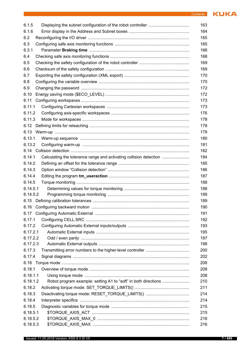
Displaying the subnet configuration of the robot controller ................................... 6.1.5 Error display in the Address and Subnet boxes .................................................... 6.1.6 Reconfiguring the I/O driver ....................................................................................... 6.2 Configuring safe axis monitoring functions ................................................................ 6.3 Parameter Braking time ...................................................................................... 6.3.1 Checking safe axis monitoring functions .................................................................... 6.4 Checking the safety configuration of the robot controller ........................................... 6.5 Checksum of the safety configuration ........................................................................ 6.6 Exporting the safety configuration (XML export) ........................................................ 6.7 Configuring the variable overview .............................................................................. 6.8 6.9 Changing the password ............................................................................................. 6.10 Energy saving mode ($ECO_LEVEL) ........................................................................ 6.11 Configuring workspaces ............................................................................................. Configuring Cartesian workspaces ....................................................................... 6.11.1 6.11.2 Configuring axis-specific workspaces ................................................................... 6.11.3 Mode for workspaces ............................................................................................ 6.12 Defining limits for reteaching ...................................................................................... 6.13 Warm-up .................................................................................................................... 6.13.1 Warm-up sequence .............................................................................................. 6.13.2 Configuring warm-up ............................................................................................ 6.14 Collision detection ...................................................................................................... 6.14.1 Calculating the tolerance range and activating collision detection ....................... 6.14.2 Defining an offset for the tolerance range ............................................................. 6.14.3 Option window “Collision detection” ...................................................................... Editing the program tm_useraction ..................................................................... 6.14.4 6.14.5 Torque monitoring ................................................................................................. Determining values for torque monitoring ........................................................ 6.14.5.1 6.14.5.2 Programming torque monitoring ...................................................................... 6.15 Defining calibration tolerances ................................................................................... 6.16 Configuring backward motion .................................................................................... 6.17 Configuring Automatic External ................................................................................. 6.17.1 Configuring CELL.SRC ......................................................................................... Configuring Automatic External inputs/outputs ..................................................... 6.17.2 Automatic External inputs ................................................................................ 6.17.2.1 Odd / even parity ............................................................................................. 6.17.2.2 6.17.2.3 Automatic External outputs .............................................................................. Transmitting error numbers to the higher-level controller ..................................... 6.17.3 6.17.4 Signal diagrams .................................................................................................... 6.18 Torque mode .............................................................................................................. 6.18.1 Overview of torque mode ...................................................................................... Using torque mode .......................................................................................... 6.18.1.1 6.18.1.2 Robot program example: setting A1 to “soft” in both directions ....................... Activating torque mode: SET_TORQUE_LIMITS() ............................................... 6.18.2 Deactivating torque mode: RESET_TORQUE_LIMITS() ..................................... 6.18.3 Interpreter specifics .............................................................................................. 6.18.4 6.18.5 Diagnostic variables for torque mode ................................................................... $TORQUE_AXIS_ACT .................................................................................... 6.18.5.1 $TORQUE_AXIS_MAX_0 ............................................................................... 6.18.5.2 6.18.5.3 $TORQUE_AXIS_MAX ................................................................................... Contents 163 164 165 165 166 168 169 169 170 170 172 172 173 173 176 178 178 179 180 181 182 184 185 186 187 188 188 189 189 190 191 192 193 195 197 198 200 202 208 208 208 210 211 214 214 215 215 216 216 Issued: 11.05.2016 Version: KSS 8.3 SI V5 7 / 499
KUKA System Software 8.3 $TORQUE_AXIS_LIMITS ............................................................................... 6.18.5.4 $HOLDING_TORQUE ..................................................................................... 6.18.5.5 6.18.5.6 Comparison: $TORQUE_AXIS_ACT and $HOLDING_TORQUE ................. 6.18.6 Other examples .................................................................................................... Robot program: setting axis to “soft” in both directions ................................... 6.18.6.1 6.18.6.2 Robot program: avoiding damage in the event of collisions ............................ Robot program: torque mode in the interrupt .................................................. 6.18.6.3 Robot program: servo gun builds up pressure ................................................ 6.18.6.4 6.18.6.5 Submit program: servo gun builds up pressure ............................................... 6.19 Event planner ............................................................................................................ Configuring a data comparison ............................................................................. 6.19.1 6.19.2 Configuring T1 and T2 Consistency, AUT and EXT Consistency ........................ 6.19.3 Configuring Logic Consistency ............................................................................. 6.20 Brake test .................................................................................................................. 6.20.1 Overview of the brake test .................................................................................... 6.20.2 Activating the brake test ....................................................................................... Programs for the brake test .................................................................................. 6.20.3 Configuring input and output signals for the brake test ........................................ 6.20.4 6.20.4.1 Signal diagram of the brake test – examples .................................................. Teaching positions for the brake test .................................................................... 6.20.5 Performing a manual brake test ........................................................................... 6.20.6 6.20.7 Checking that the brake test is functioning correctly ............................................ Program and project management ............................................................ 7 Creating a new program ............................................................................................ 7.1 7.2 Creating a new folder ................................................................................................ Renaming a file or folder ........................................................................................... 7.3 Navigator file manager ............................................................................................. 7.4 Selecting filters ..................................................................................................... 7.4.1 7.4.2 Displaying or modifying properties of files and folders ......................................... Selecting or opening a program ................................................................................ 7.5 Selecting and deselecting a program ................................................................... 7.5.1 7.5.2 Opening a program .............................................................................................. Toggling between the Navigator and the program ............................................... 7.5.3 Structure of a KRL program ....................................................................................... 7.6 7.6.1 HOME position ..................................................................................................... Displaying/hiding program sections ........................................................................... 7.7 Displaying/hiding the DEF line .............................................................................. 7.7.1 Activating detail view ............................................................................................ 7.7.2 7.7.3 Activating/deactivating the line break function ...................................................... Displaying Folds ................................................................................................... 7.7.4 Editing programs ....................................................................................................... 7.8 7.8.1 Inserting a comment or stamp .............................................................................. Deleting program lines .......................................................................................... 7.8.2 Creating folds ....................................................................................................... 7.8.3 7.8.4 Additional editing functions ................................................................................... 7.9 Printing a program ..................................................................................................... 7.10 Archiving and restoring data ...................................................................................... 7.10.1 Archiving overview ................................................................................................ 216 217 217 218 218 219 220 221 222 223 223 223 224 225 225 227 227 228 229 230 231 232 235 235 235 235 236 237 237 241 241 242 243 243 244 245 245 245 246 246 247 248 249 249 250 251 251 251 8 / 499 Issued: 11.05.2016 Version: KSS 8.3 SI V5
分享到:
收藏