logo资料库

tms320f28035寄存器速查手册.pdf

第1页 / 共234页
第2页 / 共234页
第3页 / 共234页
第4页 / 共234页
第5页 / 共234页
第6页 / 共234页
第7页 / 共234页
第8页 / 共234页
资料共234页,剩余部分请下载后查看
Flash and OTP Registers.pdf
Flash and OTP Registers
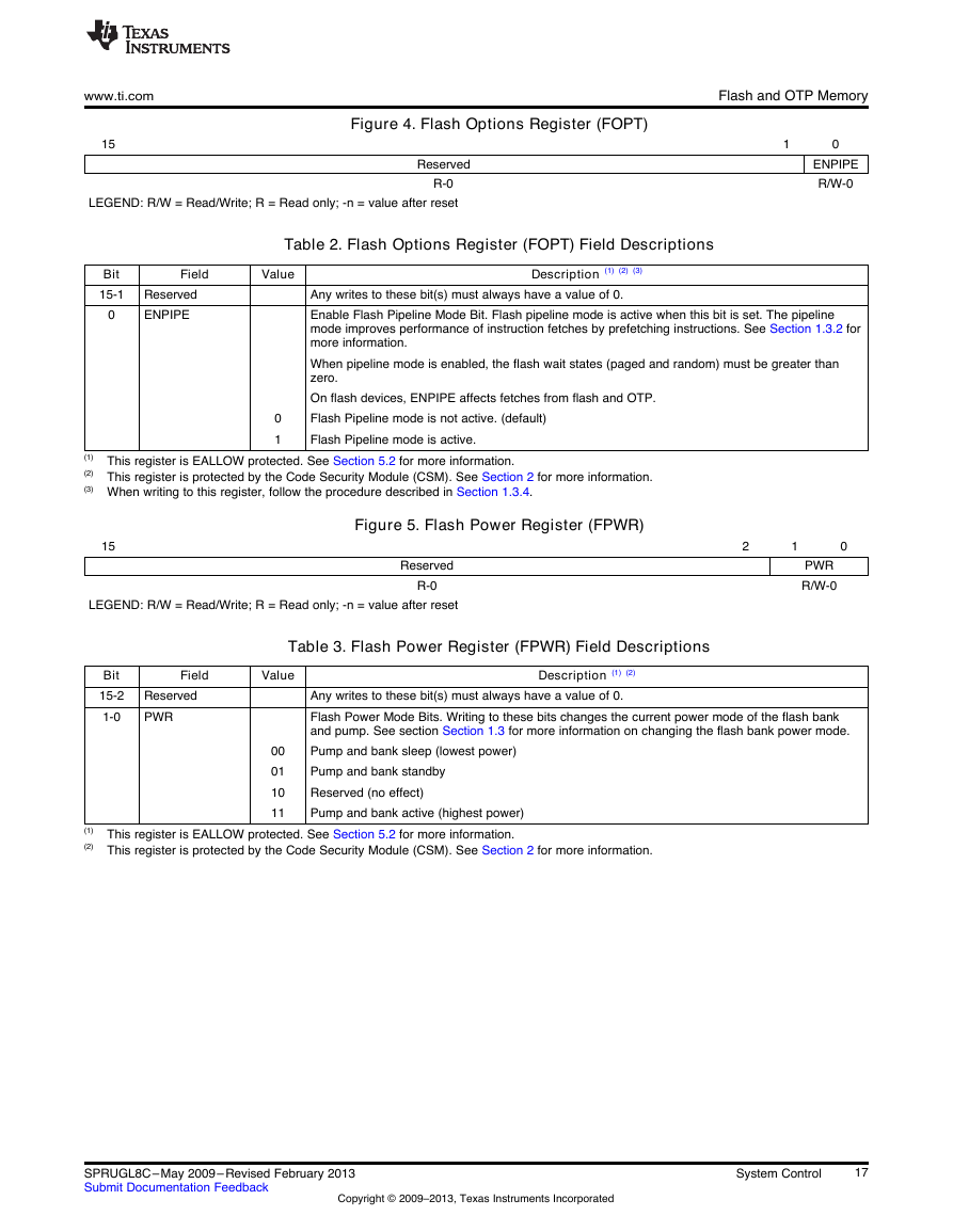
Figure 4. Flash Options Register (FOPT)
Figure 5. Flash Power Register (FPWR)
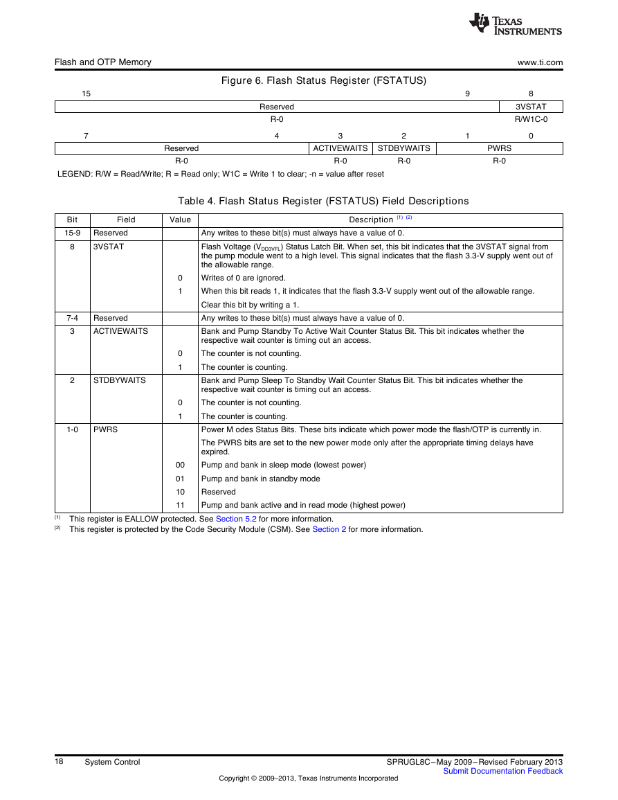
Figure 6. Flash Status Register (FSTATUS)
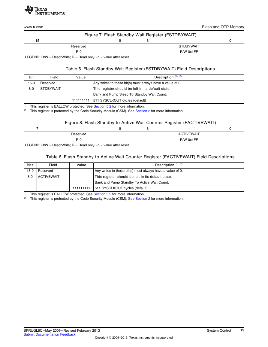
Figure 7. Flash Standby Wait Register (FSTDBYWAIT)
Figure 8. Flash Standby to Active Wait Counter Register (FACTIVEWAIT)
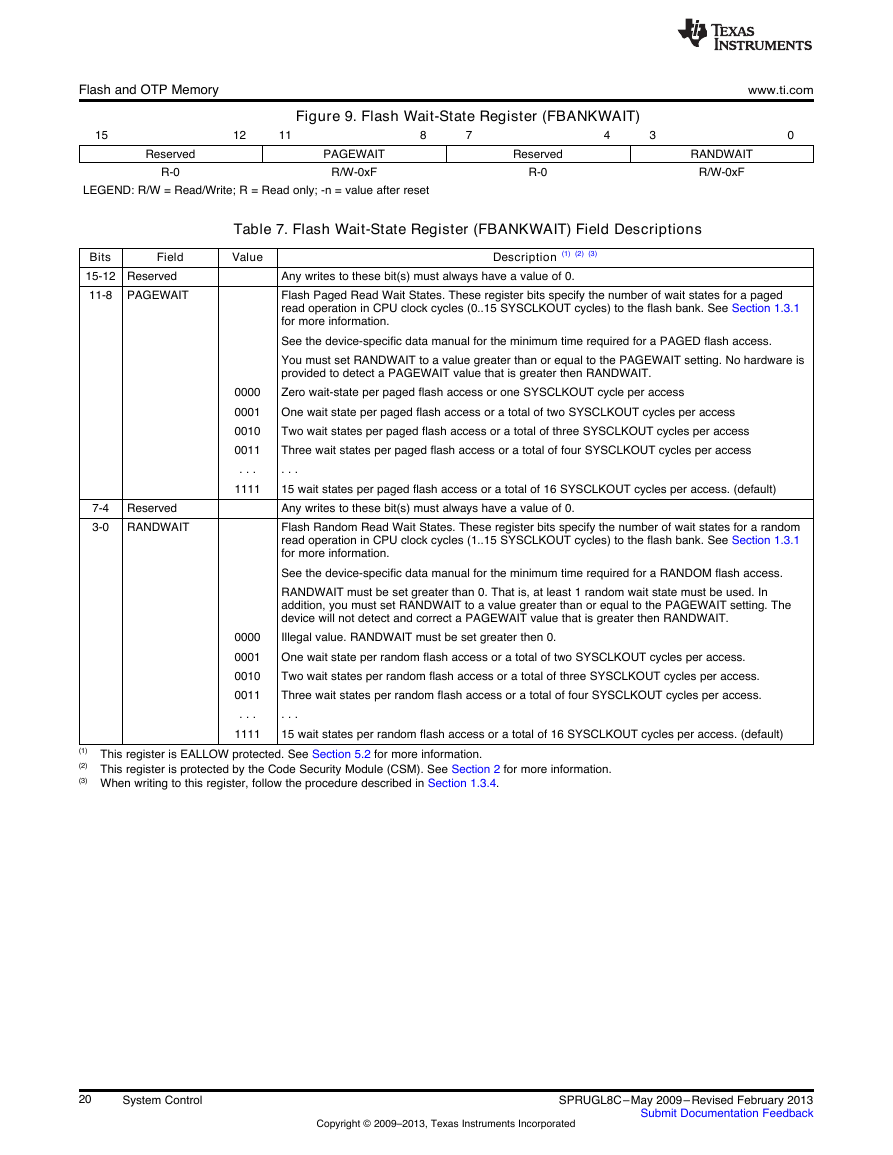
Figure 9. Flash Wait-State Register (FBANKWAIT)
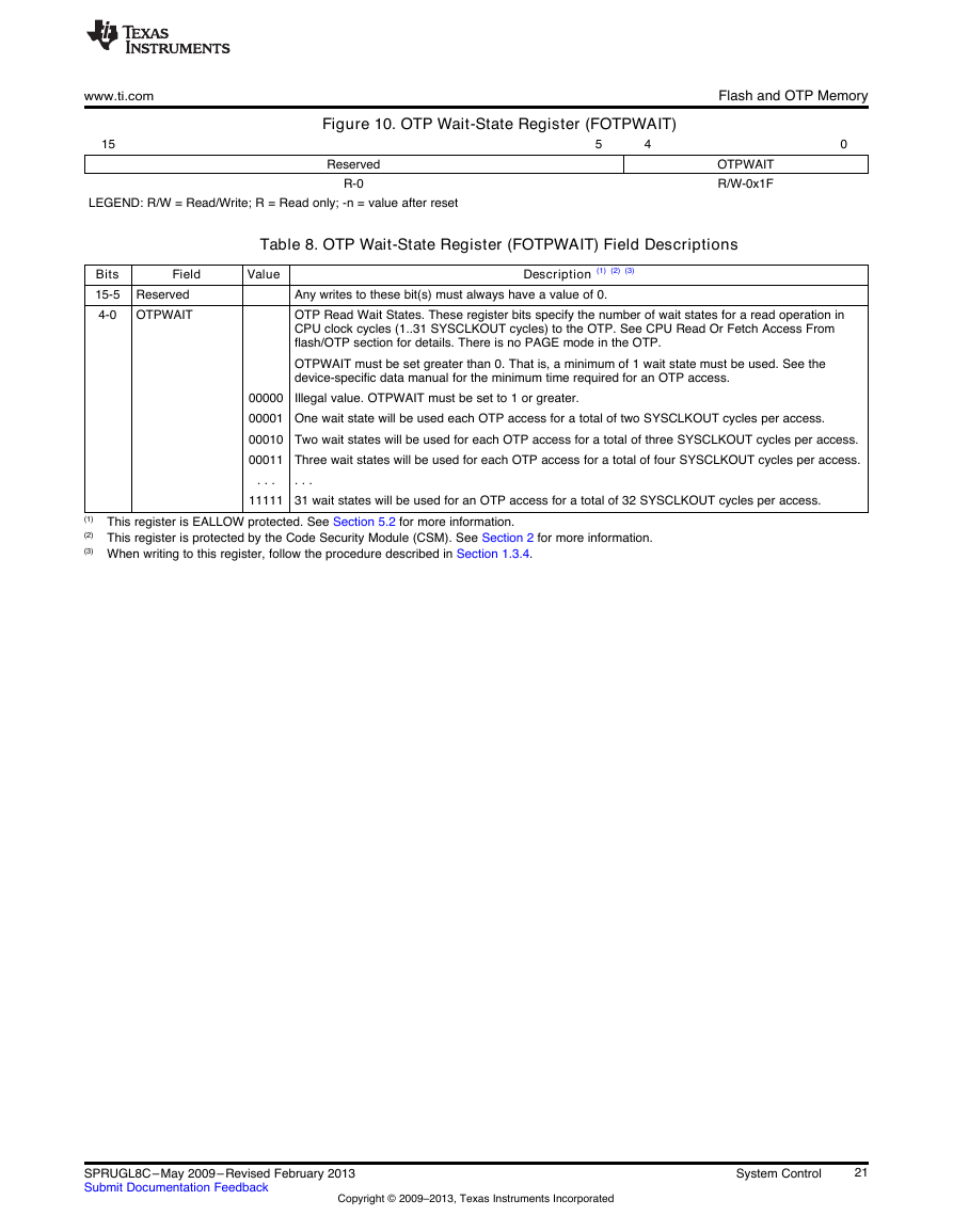
Figure 10. OTP Wait-State Register (FOTPWAIT)
CPU Timers Register.pdf
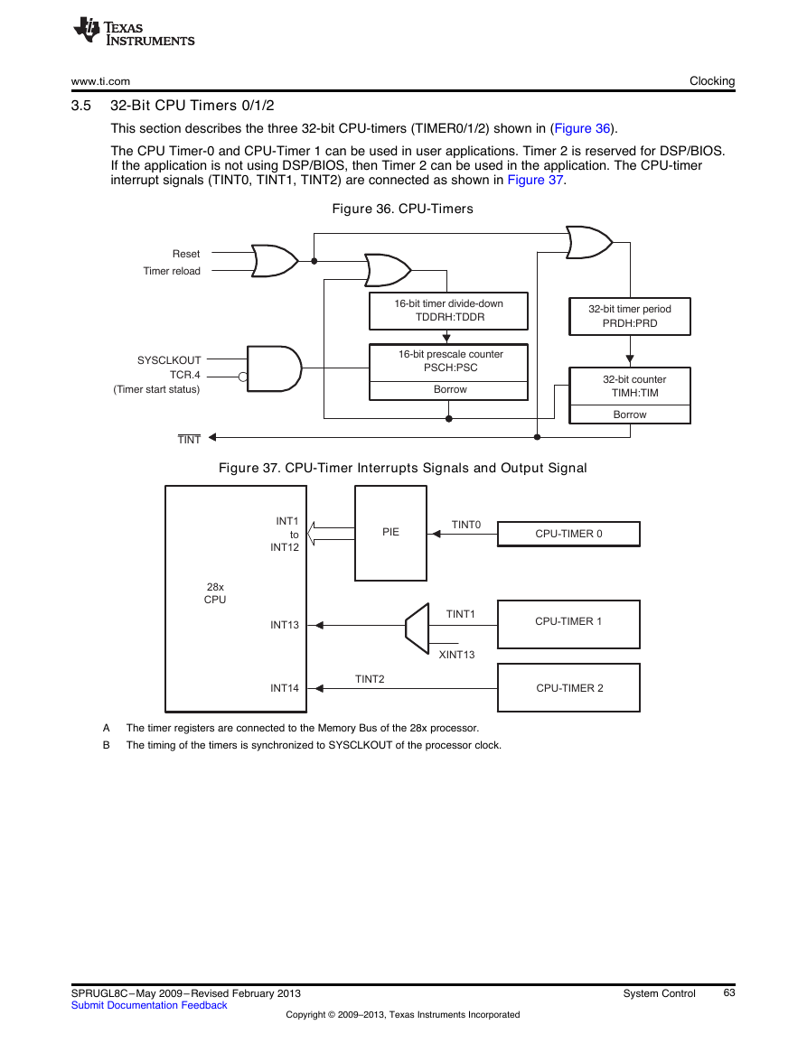
32-Bit CPU Timers 0/1/2
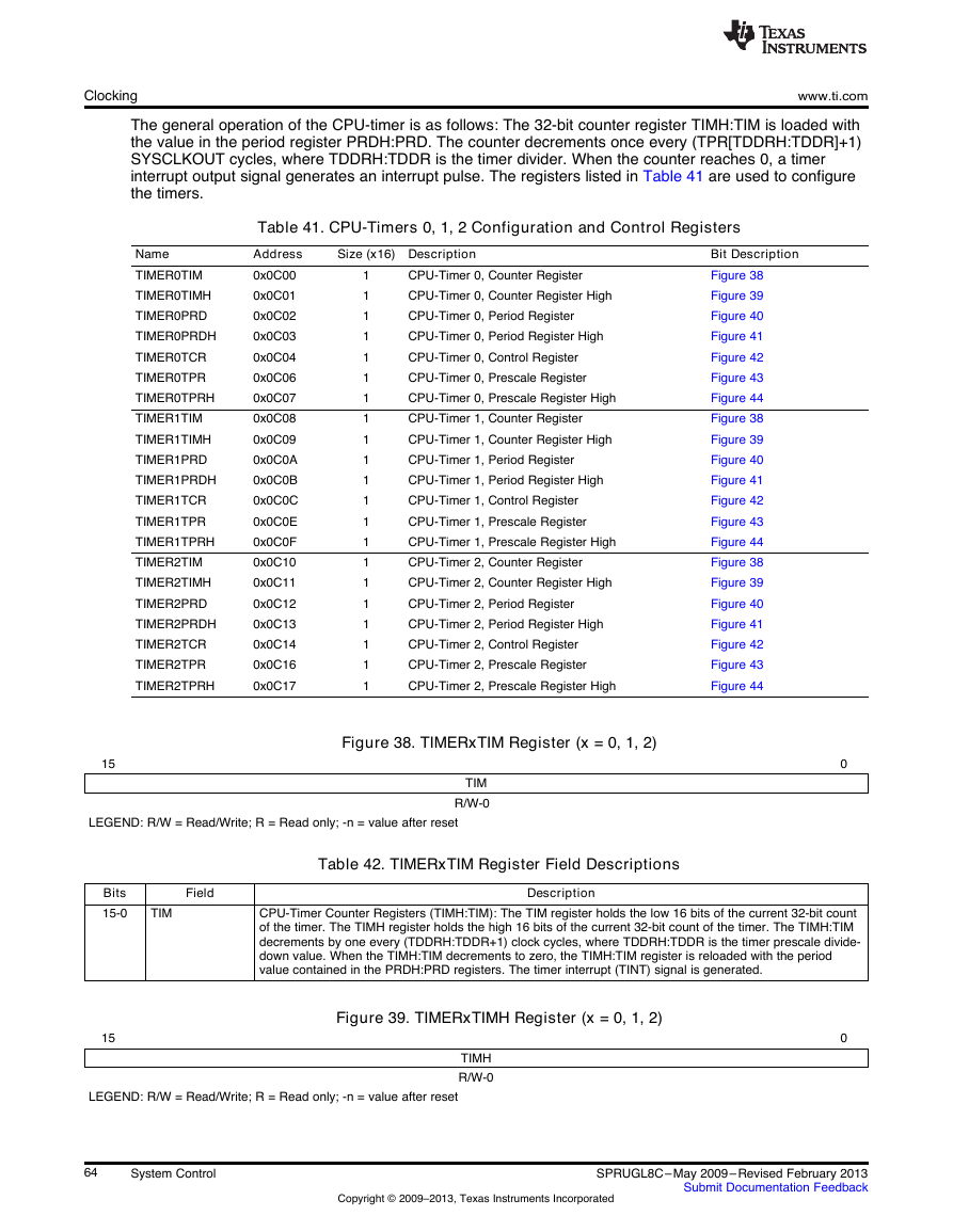
Figure 38. TIMERxTIM Register (x = 0, 1, 2)
Figure 39. TIMERxTIMH Register (x = 0, 1, 2)
Figure 40. TIMERxPRD Register (x = 0, 1, 2)
Figure 41. TIMERxPRDH Register (x = 0, 1, 2)
Figure 42. TIMERxTCR Register (x = 0, 1, 2)
Figure 43. TIMERxTPR Register (x = 0, 1, 2)
Figure 44. TIMERxTPRH Register (x = 0, 1, 2)
Clocking and System Control Register.pdf
Enabling/Disabling Clocks to the Peripheral Modules
Figure 14. Peripheral Clock Control 0 Register (PCLKCR0)
Figure 15. Peripheral Clock Control 1 Register (PCLKCR1)
Figure 16. Peripheral Clock Control 3 Register (PCLKCR3)
Figure 17. Low-Speed Peripheral Clock Prescaler Register (LOSPCP)
PLL and XCLKOUT Register.pdf
PLL Control, Status and XCLKOUT Register Descriptions
Figure 28. PLL Status Register (PLLSTS)
Figure 29. PLL Lock Period (PLLLOCKPRD) Register
PIE Interrupt Registers.pdf
PIE Interrupt Registers
Figure 81. PIECTRL Register (Address 0xCE0)
Figure 82. PIE Interrupt Acknowledge Register (PIEACK) Register (Address 0xCE1)
Figure 83. PIEIFRx Register (x = 1 to 12)
Figure 84. PIEIERx Register (x = 1 to 12)
Figure 85. Interrupt Flag Register (IFR) — CPU Register
Figure 86. Interrupt Enable Register (IER) — CPU Register
Figure 87. Debug Interrupt Enable Register (DBGIER) — CPU Register
The PIE Vector Table.pdf
Watchdog Registers.pdf
Watchdog Registers
Figure 32. System Control and Status Register (SCSR)
Figure 33. Watchdog Counter Register (WDCNTR)
Figure 34. Watchdog Reset Key Register (WDKEY)
Figure 35. Watchdog Control Register (WDCR)
External Interrupt Control Registers.pdf
External Interrupt Control Registers
Figure 88. External Interrupt n Control Register (XINTnCR)
Figure 89. External Interrupt n Counter (XINTnCTR) (Address 7078h)
GPIO Register.pdf
GPIO Register Bit Definitions
Figure 51. GPIO Port A MUX 1 (GPAMUX1) Register
Figure 52. GPIO Port A MUX 2 (GPAMUX2) Register
Figure 53. GPIO Port B MUX 1 (GPBMUX1) Register
Figure 54. Analog I/O MUX (AIOMUX1) Register
Figure 55. GPIO Port A Qualification Control (GPACTRL) Register
Figure 56. GPIO Port B Qualification Control (GPBCTRL) Register
Figure 57. GPIO Port A Qualification Select 1 (GPAQSEL1) Register
Figure 58. GPIO Port A Qualification Select 2 (GPAQSEL2) Register
Figure 59. GPIO Port B Qualification Select 1 (GPBQSEL1) Register
Figure 60. GPIO Port A Direction (GPADIR) Register
Figure 61. GPIO Port B Direction (GPBDIR) Register
Figure 62. Analog I/O DIR (AIODIR) Register
Figure 63. GPIO Port A Pullup Disable (GPAPUD) Registers
Figure 64. GPIO Port B Pullup Disable (GPBPUD) Registers
Figure 65. GPIO Port A Data (GPADAT) Register
Figure 66. GPIO Port B Data (GPBDAT) Register
Figure 67. Analog I/O DAT (AIODAT) Register
Figure 68. GPIO Port A Set, Clear and Toggle (GPASET, GPACLEAR, GPATOGGLE) Registers
Figure 69. GPIO Port B Set, Clear and Toggle (GPBSET, GPBCLEAR, GPBTOGGLE) Registers
Figure 70. Analog I/O Toggle (AIOSET, AIOCLEAR, AIOTOGGLE) Register
Figure 71. GPIO XINTn Interrupt Select (GPIOXINTnSEL) Registers
Figure 72. GPIO Low Power Mode Wakeup Select (GPIOLPMSEL) Register
EPWM Registers.pdf
4.1 Time-Base Submodule Registers
Time-Base Period Register (TBPRD)
Time Base Period High Resolution Register (TBPRDHR)
Time Base Period Mirror Register (TBPRDM)
Time-Base Period High Resolution Mirror Register (TBPRDHRM)
Time-Base Phase Register (TBPHS)
Time-Base Phase High Resolution Register (TBPHSHR)
Time-Base Counter Register (TBCTR)
Time-Base Control Register (TBCTL)
Time-Base Status Register (TBSTS)
High Resolution Period Control Register (HRPCTL)
4.2 Counter-Compare Submodule Registers
Counter-Compare A Register (CMPA)
Counter-Compare B Register (CMPB)
Counter-Compare Control Register (CMPCTL)
Counter-Compare A Mirror Register (CMPAM)
Compare A High Resolution Mirror Register(CMPAHRM)
4.3 Action-Qualifier Submodule Registers
Action-Qualifier Output A Control Register (AQCTLA)
Action-Qualifier Output B Control Register (AQCTLB)
Action-Qualifier Software Force Register (AQSFRC)
Action-Qualifier Continuous Software Force Register (AQCSFRC)
4.4 Dead-Band Submodule Registers
Dead-Band Generator Control Register (DBCTL)
Dead-Band Generator Rising Edge Delay Register (DBRED)
Dead-Band Generator Falling Edge Delay Register (DBFED
4.5 PWM-Chopper Submodule Control Register
PWM-Chopper Control Register (PCCTL)
4.6 Trip-Zone Submodule Control and Status Registers
Trip-Zone Select Register (TZSEL)
Trip-Zone Control Register (TZCTL)
Trip-Zone Enable Interrupt Register (TZEINT)
Trip-Zone Flag Register (TZFLG)
Trip-Zone Clear Register (TZCLR)
Trip-Zone Force Register (TZFRC)
Trip Zone Digital Compare Event Select Register (TZDCSEL)
4.7 Digital Compare Submodule Registers
Digital Compare Trip Select (DCTRIPSEL)
Digital Compare A Control Register (DCACTL)
Digital Compare B Control Register (DCBCTL)
Digital Compare Filter Control Register (DCFCTL)
Digital Compare Capture Control Register (DCCAPCTL)
Digital Compare Counter Capture Register (DCCAP)
Digital Compare Filter Offset Register (DCFOFFSET)
Digital Compare Filter Offset Counter Register (DCFOFFSETCNT)
Digital Compare Filter Window Register (DCFWINDOW)
Digital Compare Filter Window Counter Register (DCFWINDOWCNT)
4.8 Event-Trigger Submodule Registers
Event-Trigger Selection Register (ETSEL)
Event-Trigger Prescale Register (ETPS)
Event-Trigger Flag Register (ETFLG)15
Event-Trigger Clear Register (ETCLR)
Event-Trigger Force Register (ETFRC)
HRPWM Register.pdf
HRPWM Register
Figure 15. HRPWM Configuration Register (HRCNFG)
Figure 16. Counter Compare A High Resolution Register (CMPAHR)
Figure 17. TB Phase High Resolution Register (TBPHSHR)
Figure 18. Time Base Period High Resolution Register
Figure 19. Compare A High Resolution Mirror Register
Figure 20. Time-Base Period High Resolution Mirror Register15
Figure 21. High Resolution Period Control Register (HRPCTL)
Figure 22. High Resolution Micro Step Register (HRMSTEP) (EALLOW protected)
Figure 23. High Resolution Power Register (HRPWR) (EALLOW protected)
ECap Registers.pdf
Capture Module - Control and Status Registers
Figure 9. Time-Stamp Counter Register (TSCTR)
Figure 10. Counter Phase Control Register (CTRPHS)
Figure 11. Capture-1 Register (CAP1)
Figure 12. Capture-2 Register (CAP2)31
Figure 13. Capture-3 Register (CAP3)
Figure 14. Capture-4 Register (CAP4)
Figure 15. ECAP Control Register 1 (ECCTL1)
Figure 16. ECAP Control Register 2 (ECCTL2)
Figure 17. ECAP Interrupt Enable Register (ECEINT)
Figure 18. ECAP Interrupt Flag Register (ECFLG)
Figure 19. ECAP Interrupt Clear Register (ECCLR)
Figure 20. ECAP Interrupt Forcing Register (ECFRC)
Register Mapping
EQEP Registers.pdf
eQEP Registers
Figure 21. QEP Decoder Control (QDECCTL) Register
Figure 22. eQEP Control (QEPCTL) Register
Figure 23. eQEP Position-compare Control (QPOSCTL) Register
Figure 24. eQEP Capture Control (QCAPCTL) Register
Figure 25. eQEP Position Counter (QPOSCNT) Register
Figure 26. eQEP Position Counter Initialization (QPOSINIT) Register
Figure 27. eQEP Maximum Position Count Register (QPOSMAX) Register
Figure 28. eQEP Position-compare (QPOSCMP) Register
Figure 29. eQEP Index Position Latch (QPOSILAT) Register
Figure 30. eQEP Strobe Position Latch (QPOSSLAT) Register
Figure 31. eQEP Position Counter Latch (QPOSLAT) Register
Figure 32. eQEP Unit Timer (QUTMR) Register
Figure 33. eQEP Register Unit Period (QUPRD) Register
Figure 34. eQEP Watchdog Timer (QWDTMR) Register
Figure 35. eQEP Watchdog Period (QWDPRD) Register
Figure 36. eQEP Interrupt Enable (QEINT) Register
Figure 37. eQEP Interrupt Flag (QFLG) Register
Figure 38. eQEP Interrupt Clear (QCLR) Register
Figure 39. eQEP Interrupt Force (QFRC) Register
Figure 40. eQEP Status (QEPSTS) Register
Figure 41. eQEP Capture Timer (QCTMR) Register
Figure 42. eQEP Capture Period (QCPRD) Register
Figure 43. eQEP Capture Timer Latch (QCTMRLAT) Register
Figure 44. eQEP Capture Period Latch (QCPRDLAT) Register
ADC Registers.pdf
ADC Registers
ADC Control Register 1 (ADCCTL1)
Figure 8. ADC Control Register 1 (ADCCTL1)
ADC Control Register 2 (ADCCTL2)
Figure 9. ADC Control Register 2 (ADCCTL2)
ADC Interrupt Registers
Figure 10. ADC Interrupt Flag Register (ADCINTFLG)
Figure 11. ADC Interrupt Flag Clear Register (ADCINTFLGCLR)
Figure 12. ADC Interrupt Overflow Register (ADCINTOVF)
Figure 13. ADC Interrupt Overflow Clear Register (ADCINTOVFCLR)
Figure 14. Interrupt Select 1 And 2 Register (INTSEL1N2)
Figure 15. Interrupt Select 3 And 4 Register (INTSEL3N4)
Figure 16. Interrupt Select 5 And 6 Register (INTSEL5N6)
Figure 17. Interrupt Select 7 And 8 Register (INTSEL7N8)
Figure 18. Interrupt Select 9 And 10 Register (INTSEL9N10)
Table 9. INTSELxNy Register Field Descriptions
ADC Priority Register
Figure 19. ADC Start of Conversion Priority Control Register (SOCPRICTL)
ADC SOC Registers
Figure 20. ADC Sample Mode Register (ADCSAMPLEMODE)
Figure 21. ADC Interrupt Trigger SOC Select 1 Register (ADCINTSOCSEL1)
Figure 22. ADC Interrupt Trigger SOC Select 2 Register (ADCINTSOCSEL2)
Figure 23. ADC SOC Flag 1 Register (ADCSOCFLG1)
Figure 24. ADC SOC Force 1 Register (ADCSOCFRC1)
Figure 25. ADC SOC Overflow 1 Register (ADCSOCOVF1)
Figure 26. ADC SOC Overflow Clear 1 Register (ADCSOCOVFCLR1)
Figure 27. ADC SOC0 - SOC15 Control Registers (ADCSOCxCTL)
ADC Calibration Registers
Figure 28. ADC Reference/Gain Trim Register (ADCREFTRIM)
Figure 29. ADC Offset Trim Register (ADCOFFTRIM)
Comparator Hysteresis Control Register
Figure 30. Comparator Hysteresis Control Register (COMPHYSTCTL)
ADC Revision Register
Figure 31. ADC Revision Register (ADCREV)
ADC Result Registers
Figure 32. ADC RESULT0 - RESULT15 Registers (ADCRESULTx)
Comparator Registers.pdf
Comparator Registers
Comparator Control (COMPCTL) Register
Compare Output Status (COMPSTS) Register
DAC Control (DACCTL) Register
DAC Value (DACVAL) Register
Ramp Generator Maximum Reference Active (RAMPMAXREF_ACTIVE) Register
Ramp Generator Maximum Reference Shadow (RAMPMAXREF_SHDW) Register
Ramp Generator Decrement Value Active (RAMPDECVAL_ACTIVE) Register
Ramp Generator Decrement Value Shadow (RAMPDECVAL_SHDW) Register
Ramp Generator Status (RAMPSTS) Register
SPI Registers.pdf
SPI Control Registers
SPI Configuration Control Register (SPICCR)
SPI Operation Control Register (SPICTL)
SPI Status Register (SPIST)
SPI Baud Rate Register (SPIBRR)
SPI Emulation Buffer Register (SPIRXEMU)
SPI Serial Receive Buffer Register (SPIRXBUF)
SPI Serial Transmit Buffer Register (SPITXBUF)
SPI Serial Data Register (SPIDAT)
SPI FIFO Transmit, Receive, and Control Registers
SPI Priority Control Register (SPIPRI)
SCI Registers.pdf
SCI Registers
SCI Communication Control Register (SCICCR)
SCI Control Register 1 (SCICTL1)
SCI Baud-Select Registers (SCIHBAUD, SCILBAUD)
SCI Control Register 2 (SCICTL2)
SCI Receiver Status Register (SCIRXST)
Receiver Data Buffer Registers (SCIRXEMU, SCIRXBUF)
SCI Transmit Data Buffer Register (SCITXBUF)
SCI FIFO Registers (SCIFFTX, SCIFFRX, SCIFFCT)
Priority Control Register (SCIPRI)
I2C Module Registers.pdf
I2C Module Registers
I2C Mode Register (I2CMDR)
I2C Extended Mode Register (I2CEMDR)
I2C Interrupt Enable Register (I2CIER)
I2C Status Register (I2CSTR)
I2C Interrupt Source Register (I2CISRC)
I2C Prescaler Register (I2CPSC)
I2C Clock Divider Registers (I2CCLKL and I2CCLKH)
I2C Slave Address Register (I2CSAR)
I2C Own Address Register (I2COAR)
I2C Data Count Register (I2CCNT)
I2C Data Receive Register (I2CDRR)
I2C Data Transmit Register (I2CDXR)
I2C Transmit FIFO Register (I2CFFTX)
I2C Receive FIFO Register (I2CFFRX)
ECAN Registers.pdf
eCAN Registers
Mailbox Enable Register (CANME)
Mailbox-Direction Register (CANMD)
Transmission-Request Set Register (CANTRS
Transmission-Request-Reset Register (CANTRR)
Transmission-Acknowledge Register (CANTA)
Abort-Acknowledge Register (CANAA)
Received-Message-Pending Register (CANRMP)
Received-Message-Lost Register (CANRML)
Remote-Frame-Pending Register (CANRFP)
Global Acceptance Mask Register (CANGAM)
Master Control Register (CANMC)
Bit-Timing Configuration Register (CANBTC)
Error and Status Register (CANES)
CAN Error Counter Registers (CANTEC/CANREC)
Figure 18. Transmit-Error-Counter Register (CANTEC)
Figure 19. Receive-Error-Counter Register (CANREC
Interrupt Registers
Global Interrupt Flag Registers (CANGIF0/CANGIF1)
Figure 20. Global Interrupt Flag 0 Register (CANGIF0)
Figure 21. Global Interrupt Flag 1 Register (CANGIF1)
Global Interrupt Mask Register (CANGIM)
Mailbox Interrupt Mask Register (CANMIM)
Mailbox Interrupt Level Register (CANMIL)
Overwrite Protection Control Register (CANOPC)
eCAN I/O Control Registers (CANTIOC, CANRIOC)
Figure 26. TX I/O Control Register (CANTIOC)
Figure 27. RX I/O Control Register (CANRIOC)
Timer Management Unit
Time-Stamp Counter Register (CANTSC)
Message Object Time Stamp Registers (MOTS)
Message-Object Time-Out Registers (MOTO)
Time-Out Control Register (CANTOC)
Time-Out Status Register (CANTOS)
Mailbox Layout
Message Identifier Register (MSGID)
Message-Control Register (MSGCTRL)
Message Data Registers (CANMDL, CANMDH)
CLA register.pdf
CLA Register
Task Interrupt Vector Registers
Figure 2. Task Interrupt Vector (MVECT1/2/3/4/5/6/7/8) Register
Configuration Registers
Control Register (MCTL)
Memory Configuration Register (MMEMCFG)
CLA Peripheral Interrupt Source Select 1 Register (MPISRCSEL1)
Interrupt Enable Register (MIER)
Interrupt Flag Register (MIFR)
Interrupt Overflow Flag Register (MIOVF)
Interrupt Run Status Register (MIRUN)
Interrupt Force Register (MIFRC)
Interrupt Flag Clear Register (MICLR)
Interrupt Overflow Flag Clear Register (MICLROVF)
Execution Registers
MPC Register
Figure 13. Program Counter (MPC)
MSTF Register
Figure 14. CLA Status Register (MSTF)
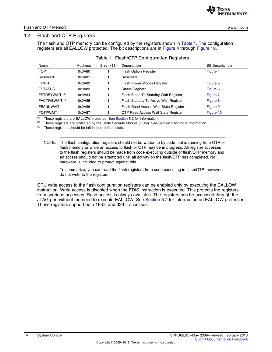
Flash and OTP Memory 1.4 Flash and OTP Registers The flash and OTP memory can be configured by the registers shown in Table 1. The configuration registers are all EALLOW protected. The bit descriptions are in Figure 4 through Figure 10. www.ti.com Table 1. Flash/OTP Configuration Registers Size (x16) Description Address 0x0A80 0x0A81 0x0A82 0x0A83 0x0A84 0x0A85 0x0A86 0x0A87 Name (1) (2) FOPT Reserved FPWR FSTATUS FSTDBYWAIT (3) FACTIVEWAIT (3) FBANKWAIT FOTPWAIT (1) These registers are EALLOW protected. See Section 5.2 for information. (2) These registers are protected by the Code Security Module (CSM). See Section 2 for more information. (3) These registers should be left in their default state. Flash Option Register Reserved Flash Power Modes Register Status Register Flash Sleep To Standby Wait Register Flash Standby To Active Wait Register Flash Read Access Wait State Register OTP Read Access Wait State Register 1 1 1 1 1 1 1 1 Bit Description Figure 4 Figure 5 Figure 6 Figure 7 Figure 8 Figure 9 Figure 10 NOTE: The flash configuration registers should not be written to by code that is running from OTP or flash memory or while an access to flash or OTP may be in progress. All register accesses to the flash registers should be made from code executing outside of flash/OTP memory and an access should not be attempted until all activity on the flash/OTP has completed. No hardware is included to protect against this. To summarize, you can read the flash registers from code executing in flash/OTP; however, do not write to the registers. CPU write access to the flash configuration registers can be enabled only by executing the EALLOW instruction. Write access is disabled when the EDIS instruction is executed. This protects the registers from spurious accesses. Read access is always available. The registers can be accessed through the JTAG port without the need to execute EALLOW. See Section 5.2 for information on EALLOW protection. These registers support both 16-bit and 32-bit accesses. 16 System Control Copyright © 2009–2013, Texas Instruments Incorporated SPRUGL8C–May 2009– Revised February 2013 Submit Documentation Feedback
www.ti.com 15 Figure 4. Flash Options Register (FOPT) R-0 LEGEND: R/W = Read/Write; R = Read only; -n = value after reset Reserved Flash and OTP Memory 1 0 ENPIPE R/W-0 Bit 15-1 0 Table 2. Flash Options Register (FOPT) Field Descriptions Field Value Description (1) (2) (3) Reserved ENPIPE Any writes to these bit(s) must always have a value of 0. Enable Flash Pipeline Mode Bit. Flash pipeline mode is active when this bit is set. The pipeline mode improves performance of instruction fetches by prefetching instructions. See Section 1.3.2 for more information. When pipeline mode is enabled, the flash wait states (paged and random) must be greater than zero. On flash devices, ENPIPE affects fetches from flash and OTP. Flash Pipeline mode is not active. (default) Flash Pipeline mode is active. 0 1 (1) This register is EALLOW protected. See Section 5.2 for more information. (2) This register is protected by the Code Security Module (CSM). See Section 2 for more information. (3) When writing to this register, follow the procedure described in Section 1.3.4. Figure 5. Flash Power Register (FPWR) 15 LEGEND: R/W = Read/Write; R = Read only; -n = value after reset Reserved R-0 2 1 0 PWR R/W-0 Bit 15-2 1-0 Table 3. Flash Power Register (FPWR) Field Descriptions Field Value Description (1) (2) Reserved PWR Any writes to these bit(s) must always have a value of 0. Flash Power Mode Bits. Writing to these bits changes the current power mode of the flash bank and pump. See section Section 1.3 for more information on changing the flash bank power mode. Pump and bank sleep (lowest power) Pump and bank standby Reserved (no effect) Pump and bank active (highest power) 00 01 10 11 (1) This register is EALLOW protected. See Section 5.2 for more information. (2) This register is protected by the Code Security Module (CSM). See Section 2 for more information. SPRUGL8C–May 2009– Revised February 2013 Submit Documentation Feedback Copyright © 2009–2013, Texas Instruments Incorporated System Control 17
Flash and OTP Memory 15 7 Figure 6. Flash Status Register (FSTATUS) Reserved R-0 4 3 2 ACTIVEWAITS STDBYWAITS R-0 R-0 Reserved R-0 www.ti.com 8 3VSTAT R/W1C-0 0 9 1 PWRS R-0 LEGEND: R/W = Read/Write; R = Read only; W1C = Write 1 to clear; -n = value after reset Table 4. Flash Status Register (FSTATUS) Field Descriptions Field Value Description (1) (2) Any writes to these bit(s) must always have a value of 0. Flash Voltage (VDD3VFL) Status Latch Bit. When set, this bit indicates that the 3VSTAT signal from the pump module went to a high level. This signal indicates that the flash 3.3-V supply went out of the allowable range. Writes of 0 are ignored. When this bit reads 1, it indicates that the flash 3.3-V supply went out of the allowable range. Clear this bit by writing a 1. Any writes to these bit(s) must always have a value of 0. Bank and Pump Standby To Active Wait Counter Status Bit. This bit indicates whether the respective wait counter is timing out an access. The counter is not counting. The counter is counting. Bank and Pump Sleep To Standby Wait Counter Status Bit. This bit indicates whether the respective wait counter is timing out an access. The counter is not counting. The counter is counting. Power M odes Status Bits. These bits indicate which power mode the flash/OTP is currently in. The PWRS bits are set to the new power mode only after the appropriate timing delays have expired. Pump and bank in sleep mode (lowest power) Pump and bank in standby mode Reserved Pump and bank active and in read mode (highest power) 0 1 0 1 0 1 00 01 10 11 Bit 15-9 8 Reserved 3VSTAT 7-4 3 Reserved ACTIVEWAITS 2 STDBYWAITS 1-0 PWRS (1) This register is EALLOW protected. See Section 5.2 for more information. (2) This register is protected by the Code Security Module (CSM). See Section 2 for more information. 18 System Control Copyright © 2009–2013, Texas Instruments Incorporated SPRUGL8C–May 2009– Revised February 2013 Submit Documentation Feedback
www.ti.com 15 Figure 7. Flash Standby Wait Register (FSTDBYWAIT) 9 8 Reserved R-0 STDBYWAIT R/W-0x1FF LEGEND: R/W = Read/Write; R = Read only; -n = value after reset Table 5. Flash Standby Wait Register (FSTDBYWAIT) Field Descriptions Bit 15-9 8-0 Field Value Reserved STDBYWAIT Description (1) (2) Any writes to these bit(s) must always have a value of 0. This register should be left in its default state. Bank and Pump Sleep To Standby Wait Count. 111111111 511 SYSCLKOUT cycles (default) (1) This register is EALLOW protected. See Section 5.2 for more information. (2) This register is protected by the Code Security Module (CSM). See Section 2 for more information. Figure 8. Flash Standby to Active Wait Counter Register (FACTIVEWAIT) 7 9 8 Reserved R-0 ACTIVEWAIT R/W-0x1FF LEGEND: R/W = Read/Write; R = Read only; -n = value after reset Flash and OTP Memory 0 0 Table 6. Flash Standby to Active Wait Counter Register (FACTIVEWAIT) Field Descriptions Field Bits 15-9 Reserved 8-0 ACTIVEWAIT Value 111111111 Description (1) (2) Any writes to these bit(s) must always have a value of 0. This register should be left in its default state. Bank and Pump Standby To Active Wait Count: 511 SYSCLKOUT cycles (default) (1) This register is EALLOW protected. See Section 5.2 for more information. (2) This register is protected by the Code Security Module (CSM). See Section 2 for more information. SPRUGL8C–May 2009– Revised February 2013 Submit Documentation Feedback Copyright © 2009–2013, Texas Instruments Incorporated System Control 19
Flash and OTP Memory www.ti.com Figure 9. Flash Wait-State Register (FBANKWAIT) 15 12 11 8 7 4 3 0 Reserved R-0 PAGEWAIT R/W-0xF Reserved R-0 RANDWAIT R/W-0xF LEGEND: R/W = Read/Write; R = Read only; -n = value after reset Field Bits 15-12 Reserved 11-8 PAGEWAIT 7-4 3-0 Reserved RANDWAIT Table 7. Flash Wait-State Register (FBANKWAIT) Field Descriptions Value Description (1) (2) (3) Any writes to these bit(s) must always have a value of 0. Flash Paged Read Wait States. These register bits specify the number of wait states for a paged read operation in CPU clock cycles (0..15 SYSCLKOUT cycles) to the flash bank. See Section 1.3.1 for more information. See the device-specific data manual for the minimum time required for a PAGED flash access. You must set RANDWAIT to a value greater than or equal to the PAGEWAIT setting. No hardware is provided to detect a PAGEWAIT value that is greater then RANDWAIT. Zero wait-state per paged flash access or one SYSCLKOUT cycle per access One wait state per paged flash access or a total of two SYSCLKOUT cycles per access Two wait states per paged flash access or a total of three SYSCLKOUT cycles per access Three wait states per paged flash access or a total of four SYSCLKOUT cycles per access . . . 15 wait states per paged flash access or a total of 16 SYSCLKOUT cycles per access. (default) Any writes to these bit(s) must always have a value of 0. Flash Random Read Wait States. These register bits specify the number of wait states for a random read operation in CPU clock cycles (1..15 SYSCLKOUT cycles) to the flash bank. See Section 1.3.1 for more information. See the device-specific data manual for the minimum time required for a RANDOM flash access. RANDWAIT must be set greater than 0. That is, at least 1 random wait state must be used. In addition, you must set RANDWAIT to a value greater than or equal to the PAGEWAIT setting. The device will not detect and correct a PAGEWAIT value that is greater then RANDWAIT. Illegal value. RANDWAIT must be set greater then 0. One wait state per random flash access or a total of two SYSCLKOUT cycles per access. Two wait states per random flash access or a total of three SYSCLKOUT cycles per access. Three wait states per random flash access or a total of four SYSCLKOUT cycles per access. . . . 15 wait states per random flash access or a total of 16 SYSCLKOUT cycles per access. (default) 0000 0001 0010 0011 . . . 1111 0000 0001 0010 0011 . . . 1111 (1) This register is EALLOW protected. See Section 5.2 for more information. (2) This register is protected by the Code Security Module (CSM). See Section 2 for more information. (3) When writing to this register, follow the procedure described in Section 1.3.4. 20 System Control Copyright © 2009–2013, Texas Instruments Incorporated SPRUGL8C–May 2009– Revised February 2013 Submit Documentation Feedback
www.ti.com 15 Figure 10. OTP Wait-State Register (FOTPWAIT) Reserved R-0 5 4 0 OTPWAIT R/W-0x1F Flash and OTP Memory LEGEND: R/W = Read/Write; R = Read only; -n = value after reset Field Bits 15-5 Reserved 4-0 OTPWAIT Table 8. OTP Wait-State Register (FOTPWAIT) Field Descriptions Value Description (1) (2) (3) Any writes to these bit(s) must always have a value of 0. OTP Read Wait States. These register bits specify the number of wait states for a read operation in CPU clock cycles (1..31 SYSCLKOUT cycles) to the OTP. See CPU Read Or Fetch Access From flash/OTP section for details. There is no PAGE mode in the OTP. OTPWAIT must be set greater than 0. That is, a minimum of 1 wait state must be used. See the device-specific data manual for the minimum time required for an OTP access. 00000 Illegal value. OTPWAIT must be set to 1 or greater. 00001 One wait state will be used each OTP access for a total of two SYSCLKOUT cycles per access. 00010 Two wait states will be used for each OTP access for a total of three SYSCLKOUT cycles per access. 00011 Three wait states will be used for each OTP access for a total of four SYSCLKOUT cycles per access. . . . . . . 11111 31 wait states will be used for an OTP access for a total of 32 SYSCLKOUT cycles per access. (1) This register is EALLOW protected. See Section 5.2 for more information. (2) This register is protected by the Code Security Module (CSM). See Section 2 for more information. (3) When writing to this register, follow the procedure described in Section 1.3.4. SPRUGL8C–May 2009– Revised February 2013 Submit Documentation Feedback Copyright © 2009–2013, Texas Instruments Incorporated System Control 21
www.ti.com 3.5 32-Bit CPU Timers 0/1/2 This section describes the three 32-bit CPU-timers (TIMER0/1/2) shown in (Figure 36). The CPU Timer-0 and CPU-Timer 1 can be used in user applications. Timer 2 is reserved for DSP/BIOS. If the application is not using DSP/BIOS, then Timer 2 can be used in the application. The CPU-timer interrupt signals (TINT0, TINT1, TINT2) are connected as shown in Figure 37. Clocking Figure 36. CPU-Timers Figure 37. CPU-Timer Interrupts Signals and Output Signal A B The timer registers are connected to the Memory Bus of the 28x processor. The timing of the timers is synchronized to SYSCLKOUT of the processor clock. SPRUGL8C–May 2009– Revised February 2013 Submit Documentation Feedback Copyright © 2009–2013, Texas Instruments Incorporated System Control 63 INT1toINT12INT1428xCPUTINT2TINT0PIECPU-TIMER 0CPU-TIMER 2INT13TINT1CPU-TIMER 1XINT13BorrowResetTimer reloadSYSCLKOUTTCR.4(Timer start status)TINT16-bit timer divide-down TDDRH:TDDR32-bit timer periodPRDH:PRD32-bit counterTIMH:TIM16-bit prescale counterPSCH:PSCBorrow
Clocking www.ti.com The general operation of the CPU-timer is as follows: The 32-bit counter register TIMH:TIM is loaded with the value in the period register PRDH:PRD. The counter decrements once every (TPR[TDDRH:TDDR]+1) SYSCLKOUT cycles, where TDDRH:TDDR is the timer divider. When the counter reaches 0, a timer interrupt output signal generates an interrupt pulse. The registers listed in Table 41 are used to configure the timers. Table 41. CPU-Timers 0, 1, 2 Configuration and Control Registers Name TIMER0TIM TIMER0TIMH TIMER0PRD TIMER0PRDH TIMER0TCR TIMER0TPR TIMER0TPRH TIMER1TIM TIMER1TIMH TIMER1PRD TIMER1PRDH TIMER1TCR TIMER1TPR TIMER1TPRH TIMER2TIM TIMER2TIMH TIMER2PRD TIMER2PRDH TIMER2TCR TIMER2TPR TIMER2TPRH Address 0x0C00 0x0C01 0x0C02 0x0C03 0x0C04 0x0C06 0x0C07 0x0C08 0x0C09 0x0C0A 0x0C0B 0x0C0C 0x0C0E 0x0C0F 0x0C10 0x0C11 0x0C12 0x0C13 0x0C14 0x0C16 0x0C17 Size (x16) Description 1 1 1 1 1 1 1 1 1 1 1 1 1 1 1 1 1 1 1 1 1 CPU-Timer 0, Counter Register CPU-Timer 0, Counter Register High CPU-Timer 0, Period Register CPU-Timer 0, Period Register High CPU-Timer 0, Control Register CPU-Timer 0, Prescale Register CPU-Timer 0, Prescale Register High CPU-Timer 1, Counter Register CPU-Timer 1, Counter Register High CPU-Timer 1, Period Register CPU-Timer 1, Period Register High CPU-Timer 1, Control Register CPU-Timer 1, Prescale Register CPU-Timer 1, Prescale Register High CPU-Timer 2, Counter Register CPU-Timer 2, Counter Register High CPU-Timer 2, Period Register CPU-Timer 2, Period Register High CPU-Timer 2, Control Register CPU-Timer 2, Prescale Register CPU-Timer 2, Prescale Register High Bit Description Figure 38 Figure 39 Figure 40 Figure 41 Figure 42 Figure 43 Figure 44 Figure 38 Figure 39 Figure 40 Figure 41 Figure 42 Figure 43 Figure 44 Figure 38 Figure 39 Figure 40 Figure 41 Figure 42 Figure 43 Figure 44 15 0 Figure 38. TIMERxTIM Register (x = 0, 1, 2) LEGEND: R/W = Read/Write; R = Read only; -n = value after reset TIM R/W-0 Bits 15-0 TIM Field Table 42. TIMERxTIM Register Field Descriptions Description CPU-Timer Counter Registers (TIMH:TIM): The TIM register holds the low 16 bits of the current 32-bit count of the timer. The TIMH register holds the high 16 bits of the current 32-bit count of the timer. The TIMH:TIM decrements by one every (TDDRH:TDDR+1) clock cycles, where TDDRH:TDDR is the timer prescale divide- down value. When the TIMH:TIM decrements to zero, the TIMH:TIM register is reloaded with the period value contained in the PRDH:PRD registers. The timer interrupt (TINT) signal is generated. 15 0 Figure 39. TIMERxTIMH Register (x = 0, 1, 2) LEGEND: R/W = Read/Write; R = Read only; -n = value after reset TIMH R/W-0 64 System Control Copyright © 2009–2013, Texas Instruments Incorporated SPRUGL8C–May 2009– Revised February 2013 Submit Documentation Feedback
分享到:
收藏