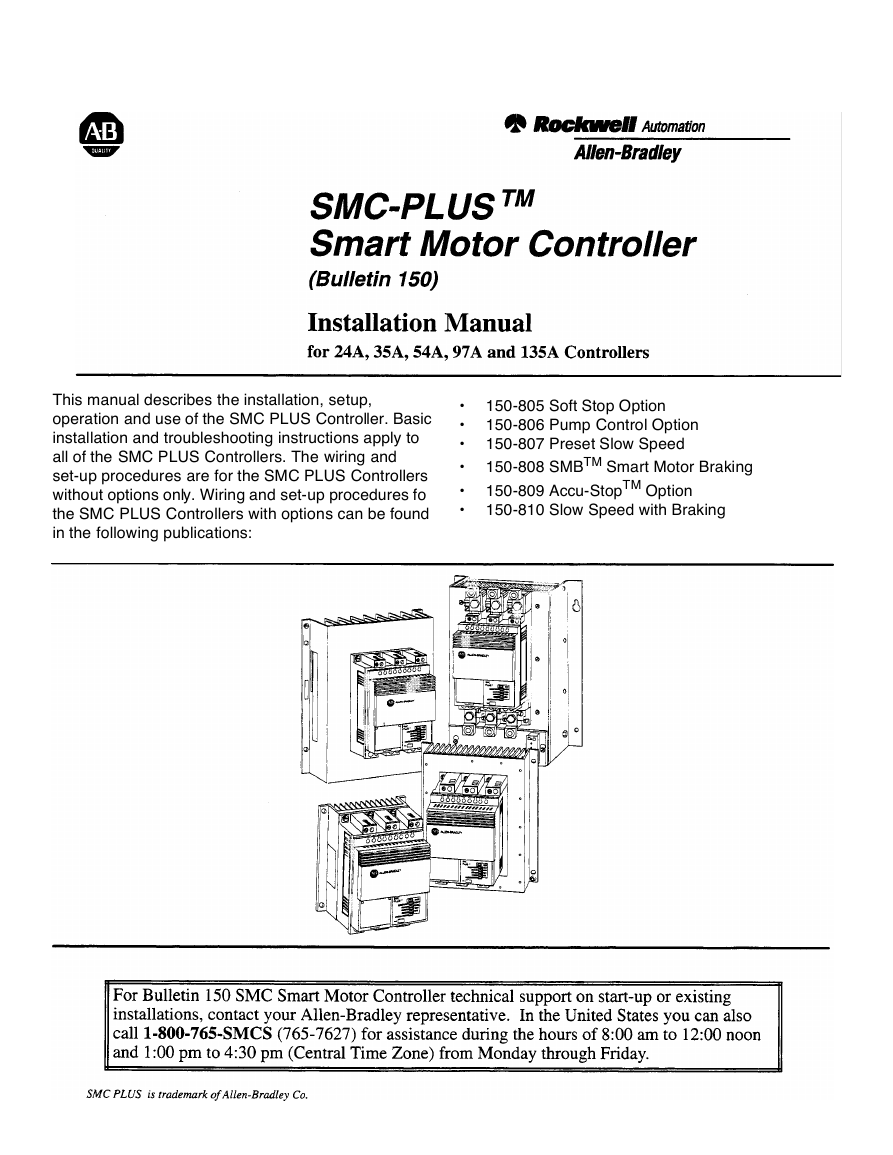
This manual describes the installation, setup,
operation and use of the SMC PLUS Controller. Basic
installation and troubleshooting instructions apply to
all of the SMC PLUS Controllers. The wiring and
set-up procedures are for the SMC PLUS Controllers
without options only. Wiring and set-up procedures fo
the SMC PLUS Controllers with options can be found
in the following publications:
•
•
•
•
•
•
150-805 Soft Stop Option
150-806 Pump Control Option
150-807 Preset Slow Speed
150-808 SMBTM Smart Motor Braking
150-809 Accu-StopTM Option
150-810 Slow Speed with Braking
�
�
Chapter
1
Catalog Number
Identification
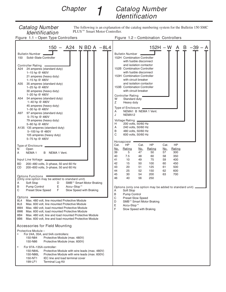
The following is an explanation of the catalog numbering system for the Bulletin 150 SMC
PLUS Smart Motor Controller.
Catalog Number
Identification
Figure 1.1 – Open Type Controllers
Figure 1.2 – Combination Controllers
150 –
A24 N
BD
A
–
8L4
152H – W A
39–B
A–
Bulletin Number
152H Combination Controller
with fusible disconnect
and isolation contactor
152B Combination Controller
with fusible disconnect
153H Combination Controller
with circuit breaker
and isolation contactor
153B Combination Controller
with circuit breaker
Controller Rating
W
Z
Standard duty
Heavy duty
Type of Enclosure
A
J
NEMA1 B NEMA 1 Vent.
NEMA12
Voltage Rating
H
A
B
C
200 volts, 50/60 Hz
240 volts, 50/60 Hz
480 volts, 50/60 Hz
600 volts, 50/60 Hz
HP
Horsepower
Cat.
No. Rating
39
40
41
42
43
44
45
46
5
7.5
10
15
20
25
30
40
HP
Cat.
No. Rating
47
48
49
50
51
52
54
56
50
60
75
100
125
150
200
250
HP
Cat.
No. Rating
57
58
59
60
61
62
63
300
350
400
450
500
600
700
Options (only one option may be added to standard unit)
A
B
C
D
E
F
Soft Stop
Pump Control
Preset Slow Speed
SMB Smart Motor Braking
Accu-Stop
Slow Speed with Braking
Bulletin Number
150 Solid–State Controller
Controller Rating
A24
24 amperes (standard duty)
1–15 hp @ 480V
21 amperes (heavy duty)
1–15 hp @ 480V
35 amperes (standard duty)
1–25 hp @ 480V
30 amperes (heavy duty)
1–20 hp @ 480V
54 amperes (standard duty)
1–40 hp @ 480V
45 amperes (heavy duty)
1–30 hp @ 480V
97 amperes (standard duty)
5–75 hp @ 480V
79 amperes (heavy duty)
5–60 hp @ 480V
A35
A54
A97
A135 135 amperes (standard duty)
5–100 hp @ 480V
105 amperes (heavy duty)
5–75 hp @ 480V
Type of Enclosure
N
A
Open
NEMA 1
B NEMA 1 Vent.
Input Line Voltage
BD
CD
200–480 volts, 3–phase, 50 and 60 Hz
200–600 volts, 3–phase, 50 and 60 Hz
Options Functions
(Only one option may be added to standard unit)
A
B
C
Soft Stop
Pump Control
Preset Slow Speed
SMB Smart Motor Braking
Accu–Stop
Slow Speed with Braking
D
E
F
Options
8L4 Max. 480 volt, line mounted Protective Module
8L6 Max. 600 volt, line mounted Protective Module
8M4 Max. 480 volt, load mounted Protective Module
8M6 Max. 600 volt, load mounted Protective Module
8B4 Max. 480 volt, line and load mounted Protective Module
8B6 Max. 600 volt, line and load mounted Protective Module
Accessories for Field Mounting
Protective Module –
•
For 24A, 35A, and 54A controllers:
150-N84
150-N86
Protective Module (max. 480V)
Protective Module (max. 600V)
•
For 97A–135A controller:
150-N84L
150-N86L
150-NT1
199-LF1
Protective Module with wire leads (max. 480V)
Protective Module with wire leads (max. 600V)
IEC line and load terminal cover
Terminal Lug Kit
�
1-2
Chapter
1
Catalog Number Identification
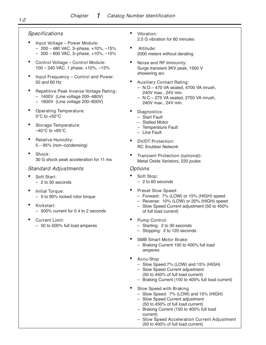
Specifications
• Input Voltage – Power Module:
– 200 – 480 VAC, 3–phase, +10%, –15%
– 200 – 600 VAC, 3–phase, +10%, –15%
• Control Voltage – Control Module:
100 – 240 VAC, 1 phase, +10%, –15%
• Input Frequency – Control and Power:
50 and 60 Hz
• Repetitive Peak Inverse Voltage Rating:
– 1400V (Line voltage 200–480V)
– 1600V (Line voltage 200–600V)
• Operating Temperature:
0°C to +50°C
• Storage Temperature:
–40°C to +85°C
• Relative Humidity:
5 – 95% (non–condensing)
• Shock:
30 G shock peak acceleration for 11 ms
Standard Adjustments
• Soft Start:
– 2 to 30 seconds
• Initial Torque:
– 5 to 90% locked rotor torque
• Kickstart:
– 500% current for 0.4 to 2 seconds
• Current Limit:
– 50 to 500% full load amperes
• Vibration:
2.5 G vibration for 60 minutes
• Altitude:
2000 meters without derating
• Noise and RF Immunity:
Surge transient 3KV peak, 1500 V
showering arc
• Auxiliary Contact Rating:
– N.O.– 470 VA sealed, 4700 VA inrush,
240V max., 24V min.
– N.C.– 275 VA sealed, 2750 VA inrush,
240V max., 24V min.
• Diagnostics:
– Start Fault
– Stalled Motor
– Temperature Fault
– Line Fault
• DV/DT Protection:
RC Snubber Network
• Transient Protection (optional):
Metal Oxide Varistors, 220 joules
Options
• Soft Stop:
– 2 to 60 seconds
• Preset Slow Speed:
– Forward: 7% (LOW) or 15% (HIGH) speed
– Reverse: 10% (LOW) or 20% (HIGH) speed
– Slow Speed Current adjustment (50 to 450%
of full load current)
• Pump Control:
– Starting: 2 to 30 seconds
– Stopping: 2 to 120 seconds
• SMB Smart Motor Brake:
– Braking Current 150 to 400% full load
amperes
• Accu-Stop
– Slow Speed:7% (LOW) and 15% (HIGH)
– Slow Speed Current adjustment
(50 to 450% of full load current)
– Braking Current (150 to 400% full load current)
• Slow Speed with Braking
– Slow Speed: 7% (LOW) and 15% (HIGH)
– Slow Speed Current adjustment
(50 to 450% of full load current)
– Braking Current (150 to 400% full load
current)
– Slow Speed Acceleration Current Adjustment
(50 to 400% of full load current)
�
Chapter
2
Installation and
Wiring
Inspection
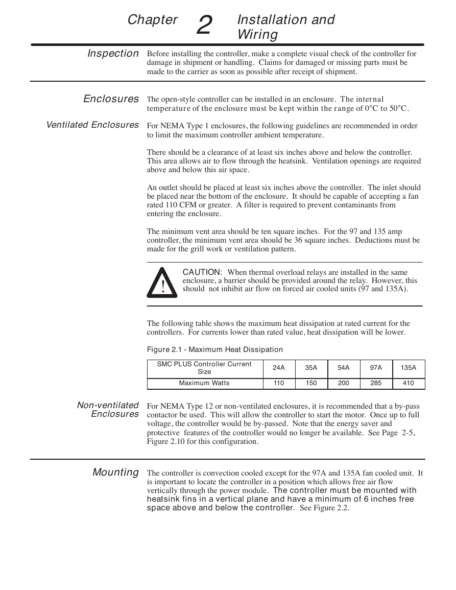
Before installing the controller, make a complete visual check of the controller for
damage in shipment or handling. Claims for damaged or missing parts must be
made to the carrier as soon as possible after receipt of shipment.
Enclosures
The open-style controller can be installed in an enclosure. The internal
temperature of the enclosure must be kept within the range of 0°C to 50°C.
Ventilated Enclosures
For NEMA Type 1 enclosures, the following guidelines are recommended in order
to limit the maximum controller ambient temperature.
There should be a clearance of at least six inches above and below the controller.
This area allows air to flow through the heatsink. Ventilation openings are required
above and below this air space.
An outlet should be placed at least six inches above the controller. The inlet should
be placed near the bottom of the enclosure. It should be capable of accepting a fan
rated 110 CFM or greater. A filter is required to prevent contaminants from
entering the enclosure.
The minimum vent area should be ten square inches. For the 97 and 135 amp
controller, the minimum vent area should be 36 square inches. Deductions must be
made for the grill work or ventilation pattern.
CAUTION: When thermal overload relays are installed in the same
enclosure, a barrier should be provided around the relay. However, this
should not inhibit air flow on forced air cooled units (97 and 135A).
!
The following table shows the maximum heat dissipation at rated current for the
controllers. For currents lower than rated value, heat dissipation will be lower.
Figure 2.1 - Maximum Heat Dissipation
SMC PLUS Controller Current
Size
Maximum Watts
24A
110
35A
150
54A
200
97A
285
135A
410
Non-ventilated
Enclosures
For NEMA Type 12 or non-ventilated enclosures, it is recommended that a by-pass
contactor be used. This will allow the controller to start the motor. Once up to full
voltage, the controller would be by-passed. Note that the energy saver and
protective features of the controller would no longer be available. See Page 2-5,
Figure 2.10 for this configuration.
Mounting
The controller is convection cooled except for the 97A and 135A fan cooled unit. It
is important to locate the controller in a position which allows free air flow
vertically through the power module. The controller must be mounted with
heatsink fins in a vertical plane and have a minimum of 6 inches free
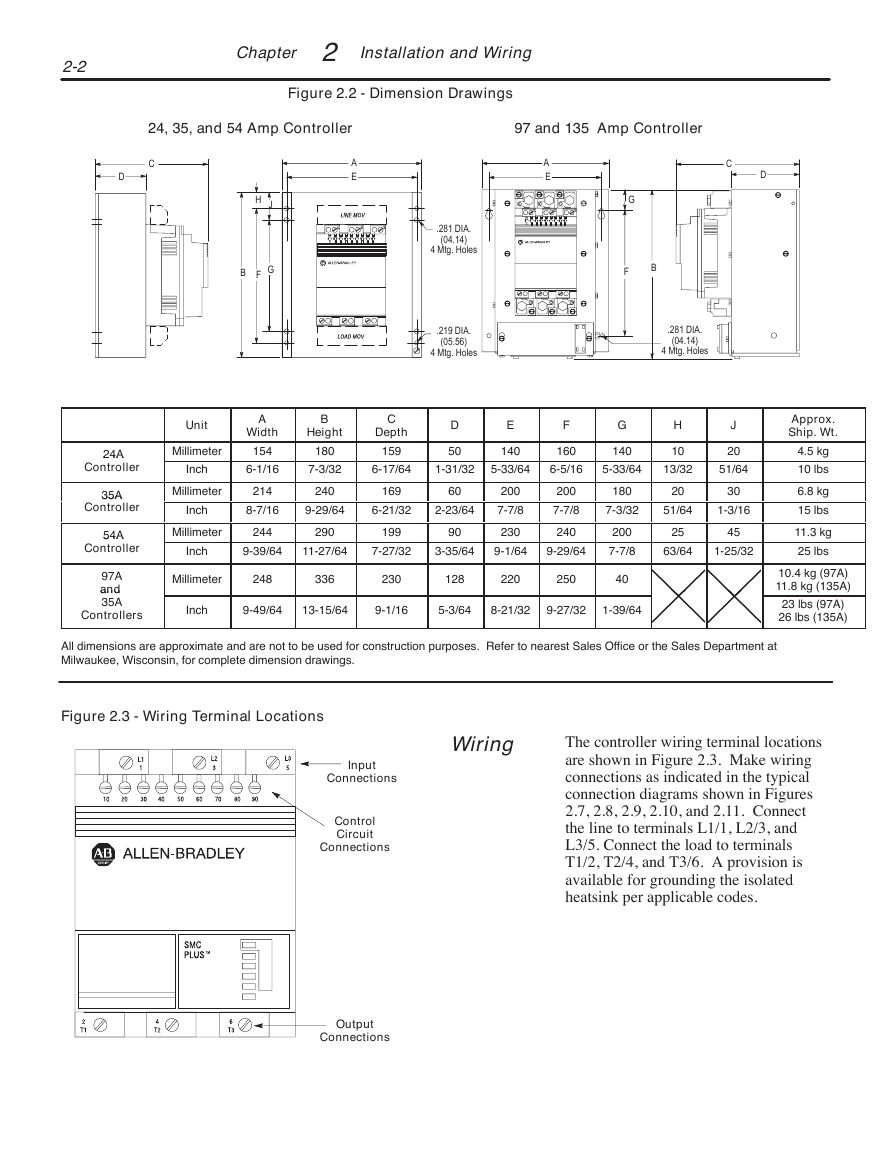
space above and below the controller. See Figure 2.2.
�
2-2
Chapter
2
Installation and Wiring
Figure 2.2 - Dimension Drawings
24, 35, and 54 Amp Controller
97 and 135 Amp Controller
C
D
A
E
A
E
C
D
H J
B F G
Unit
Millimeter
Inch
Millimeter
Inch
A
Width
154
6-1/16
214
8-7/16
B
Height
180
7-3/32
240
.281 DIA.
(04.14)
4 Mtg. Holes
.219 DIA.
(05.56)
4 Mtg. Holes
G
F
B
.281 DIA.
(04.14)
4 Mtg. Holes
C
Depth
159
D
50
E
140
F
160
G
140
H
10
J
20
6-17/64
1-31/32
5-33/64
6-5/16
5-33/64
13/32
51/64
169
60
9-29/64
6-21/32
2-23/64
200
7-7/8
230
200
7-7/8
240
180
20
30
7-3/32
51/64
1-3/16
200
7-7/8
25
45
63/64
1-25/32
Millimeter
244
290
199
90
Inch
9-39/64
11-27/64
7-27/32
3-35/64
9-1/64
9-29/64
Millimeter
248
336
230
128
220
250
40
Inch
9-49/64
13-15/64
9-1/16
5-3/64
8-21/32
9-27/32
1-39/64
Approx.
Ship. Wt.
4.5 kg
10 lbs
6.8 kg
15 lbs
11.3 kg
25 lbs
10.4 kg (97A)
11.8 kg (135A)
23 lbs (97A)
26 lbs (135A)
24A
24A
Controller
35A
35A
Controller
54A
54A
Controller
97A
and
and
35A
Controllers
All dimensions are approximate and are not to be used for construction purposes. Refer to nearest Sales Office or the Sales Department at
Milwaukee, Wisconsin, for complete dimension drawings.
Figure 2.3 - Wiring Terminal Locations
Wiring
Input
Connections
Control
Circuit
Connections
Output
Connections
The controller wiring terminal locations
are shown in Figure 2.3. Make wiring
connections as indicated in the typical
connection diagrams shown in Figures
2.7, 2.8, 2.9, 2.10, and 2.11. Connect
the line to terminals L1/1, L2/3, and
L3/5. Connect the load to terminals
T1/2, T2/4, and T3/6. A provision is
available for grounding the isolated
heatsink per applicable codes.
�
Chapter
2
Installation & Wiring
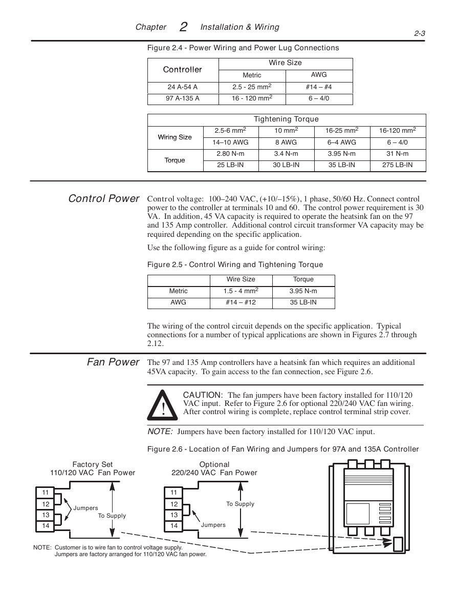
Figure 2.4 - Power Wiring and Power Lug Connections
2-3
Controller
Controller
24 A-54 A
97 A-135 A
Wire Size
Metric
2.5 - 25 mm2
16 - 120 mm2
AWG
#14 – #4
6 – 4/0
Tightening Torque
Wiring Size
Wiring Size
Torque
Torque
2.5-6 mm2
14–10 AWG
2.80 N-m
25 LB-IN
10 mm2
8 AWG
3.4 N-m
30 LB-IN
16-25 mm2
6–4 AWG
3.95 N-m
35 LB-IN
16-120 mm2
6 – 4/0
31 N-m
275 LB-IN
Control Power
Control voltage: 100–240 VAC, (+10/–15%), 1 phase, 50/60 Hz. Connect control
power to the controller at terminals 10 and 60. The control power requirement is 30
VA. In addition, 45 VA capacity is required to operate the heatsink fan on the 97
and 135 Amp controller. Additional control circuit transformer VA capacity may be
required depending on the specific application.
Use the following figure as a guide for control wiring:
Figure 2.5 - Control Wiring and Tightening Torque
Metric
AWG
Wire Size
1.5 - 4 mm2
#14 – #12
Torque
3.95 N-m
35 LB-IN
The wiring of the control circuit depends on the specific application. Typical
connections for a number of typical applications are shown in Figures 2.7 through
2.12.
Fan Power
The 97 and 135 Amp controllers have a heatsink fan which requires an additional
45VA capacity. To gain access to the fan connection, see Figure 2.6.
CAUTION: The fan jumpers have been factory installed for 110/120
VAC input. Refer to Figure 2.6 for optional 220/240 VAC fan wiring.
After control wiring is complete, replace control terminal strip cover.
!
NOTE: Jumpers have been factory installed for 110/120 VAC input.
Figure 2.6 - Location of Fan Wiring and Jumpers for 97A and 135A Controller
Factory Set
110/120 VAC Fan Power
Optional
220/240 VAC Fan Power
11
12
13
14
Jumpers
To Supply
11
12
13
14
To Supply
Jumpers
NOTE: Customer is to wire fan to control voltage supply.
Jumpers are factory arranged for 110/120 VAC fan power.
�
2-4
Chapter
2
Installation and Wiring
Typical Connection
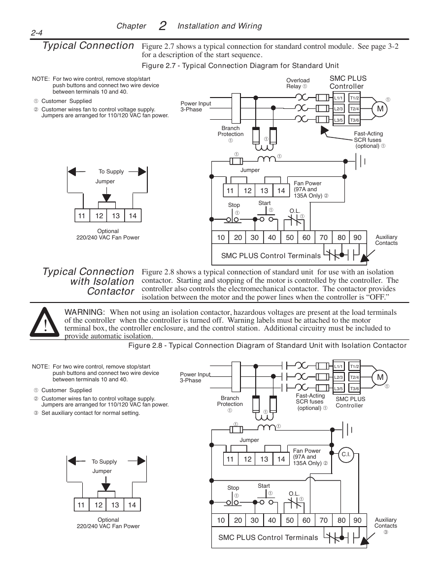
Figure 2.7 shows a typical connection for standard control module. See page 3-2
for a description of the start sequence.
Figure 2.7 - Typical Connection Diagram for Standard Unit
NOTE: For two wire control, remove stop/start
push buttons and connect two wire device
between terminals 10 and 40.
Customer Supplied
` Customer wires fan to control voltage supply.
Jumpers are arranged for 110/120 VAC fan power.
Power Input
3-Phase
To Supply
Jumper
11
12
13
14
Optional
220/240 VAC Fan Power
Overload
Relay
SMC PLUS
Controller
L1/1
T1/2
L2/3
T2/4
L3/5
T3/6
M
Fast-Acting
SCR fuses
(optional)
Branch
Protection
Jumper
11
12
13
14
Stop
Start
Fan Power
(97A and
135A Only) `
O.L.
10
20
30
40
50
60
70
80 90
Auxiliary
Contacts
SMC PLUS Control Terminals
Typical Connection
with Isolation
Contactor
Figure 2.8 shows a typical connection of standard unit for use with an isolation
contactor. Starting and stopping of the motor is controlled by the controller. The
controller also controls the electromechanical contactor. The contactor provides
isolation between the motor and the power lines when the controller is “OFF.”
!
WARNING: When not using an isolation contactor, hazardous voltages are present at the load terminals
of the controller when the controller is turned off. Warning labels must be attached to the motor
terminal box, the controller enclosure, and the control station. Additional circuitry must be included to
provide automatic isolation.
Figure 2.8 - Typical Connection Diagram of Standard Unit with Isolation Contactor
NOTE: For two wire control, remove stop/start
push buttons and connect two wire device
between terminals 10 and 40.
Power Input
3-Phase
Customer Supplied
` Customer wires fan to control voltage supply.
Jumpers are arranged for 110/120 VAC fan power.
´ Set auxiliary contact for normal setting.
L1/1
T1/2
L2/3
T2/4
L3/5
T3/6
M
Branch
Protection
Fast-Acting
SCR fuses
(optional)
SMC PLUS
Controller
To Supply
Jumper
11
12
13
14
Optional
220/240 VAC Fan Power
Jumper
11
12
13
14
Fan Power
(97A and
135A Only) `
C.I.
Stop
Start
O.L.
10
20
30
40
50
60
70
80 90
SMC PLUS Control Terminals
Auxiliary
Contacts
´
�


 2023年江西萍乡中考道德与法治真题及答案.doc
 2012年重庆南川中考生物真题及答案.doc
 2013年江西师范大学地理学综合及文艺理论基础考研真题.doc
 2020年四川甘孜小升初语文真题及答案I卷.doc
 2020年注册岩土工程师专业基础考试真题及答案.doc
 2023-2024学年福建省厦门市九年级上学期数学月考试题及答案.doc
 2021-2022学年辽宁省沈阳市大东区九年级上学期语文期末试题及答案.doc
 2022-2023学年北京东城区初三第一学期物理期末试卷及答案.doc
 2018上半年江西教师资格初中地理学科知识与教学能力真题及答案.doc
 2012年河北国家公务员申论考试真题及答案-省级.doc
 2020-2021学年江苏省扬州市江都区邵樊片九年级上学期数学第一次质量检测试题及答案.doc
 2022下半年黑龙江教师资格证中学综合素质真题及答案.doc