logo资料库

nRF51 用户手册.pdf

第1页 / 共174页
第2页 / 共174页
第3页 / 共174页
第4页 / 共174页
第5页 / 共174页
第6页 / 共174页
第7页 / 共174页
第8页 / 共174页
资料共174页,剩余部分请下载后查看
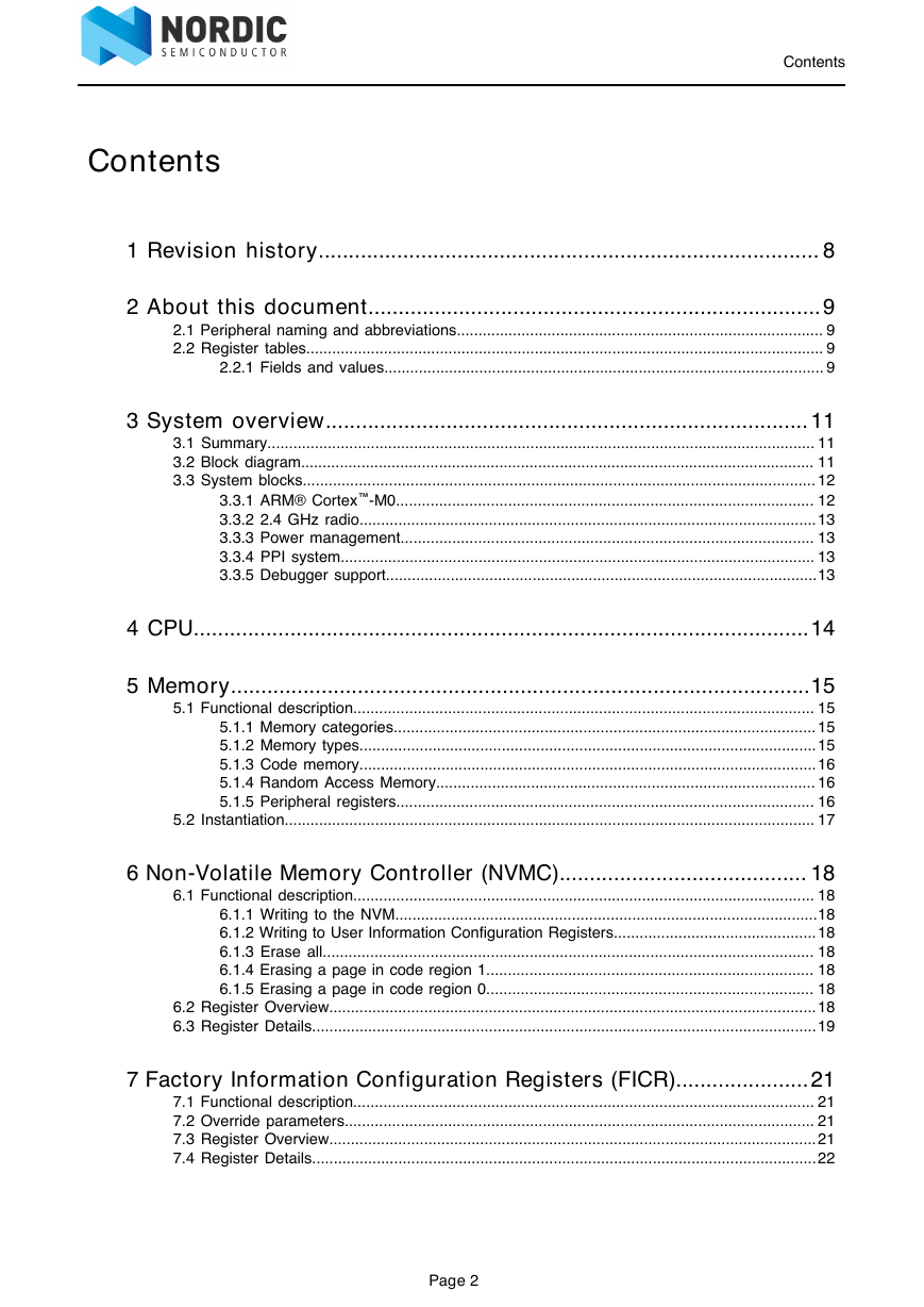
Contents
1 Revision history
2 About this document
2.1 Peripheral naming and abbreviations
2.2 Register tables
2.2.1 Fields and values
3 System overview
3.1 Summary
3.2 Block diagram
3.3 System blocks
3.3.1 ARM® Cortex™-M0
3.3.2 2.4 GHz radio
3.3.3 Power management
3.3.4 PPI system
3.3.5 Debugger support
4 CPU
5 Memory
5.1 Functional description
5.1.1 Memory categories
5.1.2 Memory types
5.1.3 Code memory
5.1.4 Random Access Memory
5.1.5 Peripheral registers
5.2 Instantiation
6 Non-Volatile Memory Controller (NVMC)
6.1 Functional description
6.1.1 Writing to the NVM
6.1.2 Writing to User Information Configuration Registers
6.1.3 Erase all
6.1.4 Erasing a page in code region 1
6.1.5 Erasing a page in code region 0
6.2 Register Overview
6.3 Register Details
7 Factory Information Configuration Registers (FICR)
7.1 Functional description
7.2 Override parameters
7.3 Register Overview
7.4 Register Details
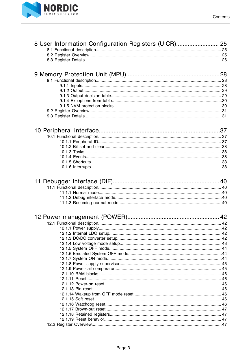
8 User Information Configuration Registers (UICR)
8.1 Functional description
8.2 Register Overview
8.3 Register Details
9 Memory Protection Unit (MPU)
9.1 Functional description
9.1.1 Inputs
9.1.2 Output
9.1.3 Output decision table
9.1.4 Exceptions from table
9.1.5 NVM protection blocks
9.2 Register Overview
9.3 Register Details
10 Peripheral interface
10.1 Functional description
10.1.1 Peripheral ID
10.1.2 Bit set and clear
10.1.3 Tasks
10.1.4 Events
10.1.5 Shortcuts
10.1.6 Interrupts
11 Debugger Interface (DIF)
11.1 Functional description
11.1.1 Normal mode
11.1.2 Debug interface mode
11.1.3 Resuming normal mode
12 Power management (POWER)
12.1 Functional description
12.1.1 Power supply
12.1.2 Internal LDO setup
12.1.3 DC/DC converter setup
DC/DC efficiency
12.1.4 Low voltage mode setup
12.1.5 System OFF mode
12.1.6 Emulated System OFF mode
12.1.7 System ON mode
Sub power modes
12.1.8 Power supply supervisor
12.1.9 Power-fail comparator
12.1.10 RAM blocks
12.1.11 Reset
12.1.12 Power-on reset
12.1.13 Pin reset
12.1.14 Wakeup from OFF mode reset
12.1.15 Soft reset
12.1.16 Watchdog reset
12.1.17 Brown-out reset
12.1.18 Retained registers
12.1.19 Reset behavior
12.2 Register Overview
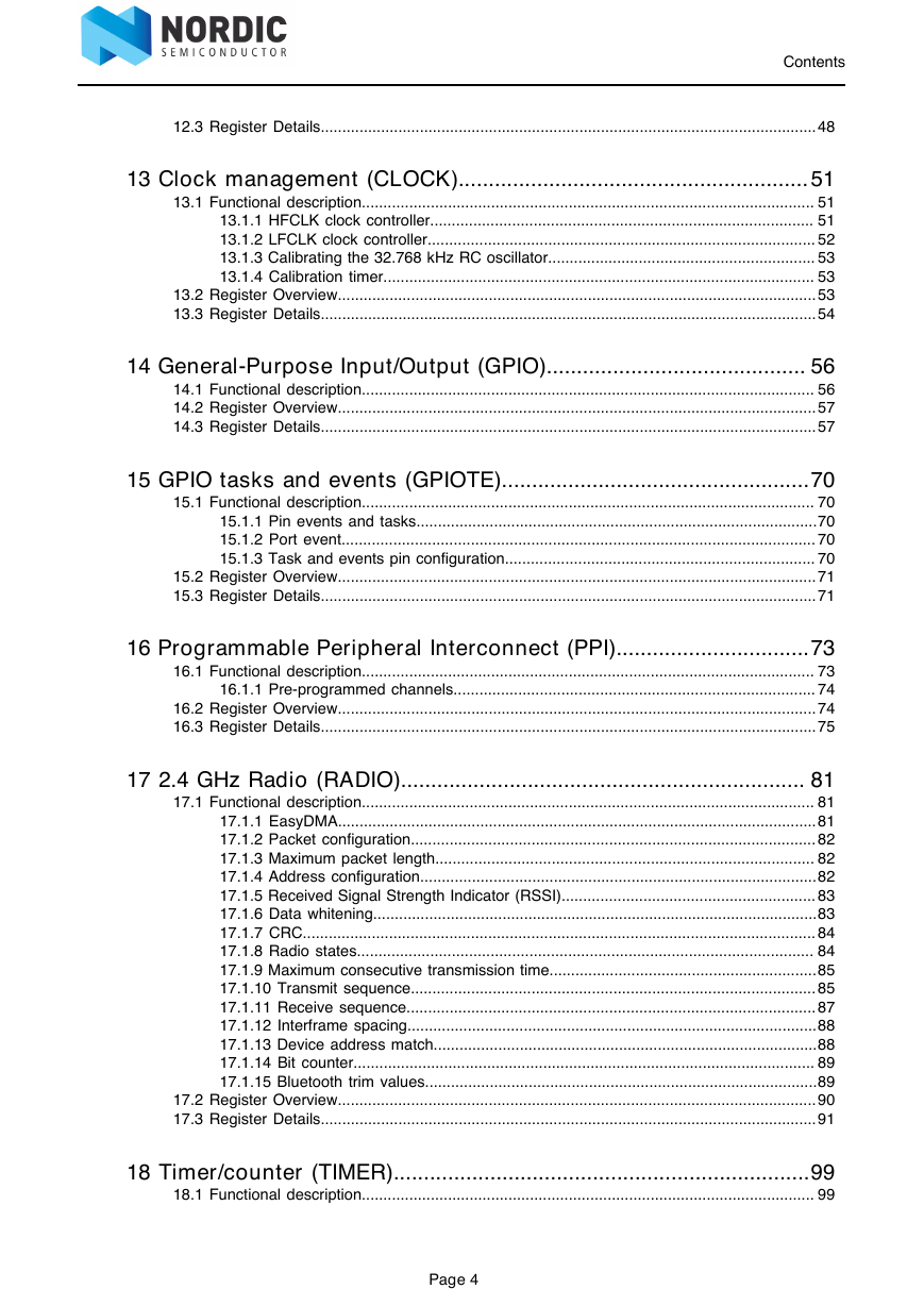
12.3 Register Details
13 Clock management (CLOCK)
13.1 Functional description
13.1.1 HFCLK clock controller
13.1.2 LFCLK clock controller
13.1.3 Calibrating the 32.768 kHz RC oscillator
13.1.4 Calibration timer
13.2 Register Overview
13.3 Register Details
14 General-Purpose Input/Output (GPIO)
14.1 Functional description
14.2 Register Overview
14.3 Register Details
15 GPIO tasks and events (GPIOTE)
15.1 Functional description
15.1.1 Pin events and tasks
15.1.2 Port event
15.1.3 Task and events pin configuration
15.2 Register Overview
15.3 Register Details
16 Programmable Peripheral Interconnect (PPI)
16.1 Functional description
16.1.1 Pre-programmed channels
16.2 Register Overview
16.3 Register Details
17 2.4 GHz Radio (RADIO)
17.1 Functional description
17.1.1 EasyDMA
17.1.2 Packet configuration
17.1.3 Maximum packet length
17.1.4 Address configuration
17.1.5 Received Signal Strength Indicator (RSSI)
17.1.6 Data whitening
17.1.7 CRC
17.1.8 Radio states
17.1.9 Maximum consecutive transmission time
17.1.10 Transmit sequence
17.1.11 Receive sequence
17.1.12 Interframe spacing
17.1.13 Device address match
17.1.14 Bit counter
17.1.15 Bluetooth trim values
17.2 Register Overview
17.3 Register Details
18 Timer/counter (TIMER)
18.1 Functional description
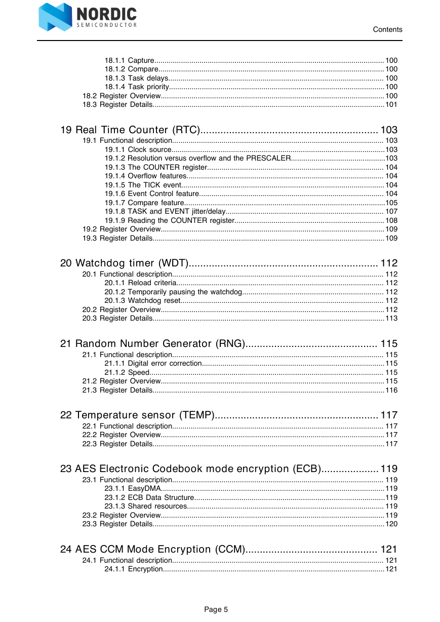
18.1.1 Capture
18.1.2 Compare
18.1.3 Task delays
18.1.4 Task priority
18.2 Register Overview
18.3 Register Details
19 Real Time Counter (RTC)
19.1 Functional description
19.1.1 Clock source
19.1.2 Resolution versus overflow and the PRESCALER
19.1.3 The COUNTER register
19.1.4 Overflow features
19.1.5 The TICK event
19.1.6 Event Control feature
19.1.7 Compare feature
19.1.8 TASK and EVENT jitter/delay
19.1.9 Reading the COUNTER register
19.2 Register Overview
19.3 Register Details
20 Watchdog timer (WDT)
20.1 Functional description
20.1.1 Reload criteria
20.1.2 Temporarily pausing the watchdog
20.1.3 Watchdog reset
20.2 Register Overview
20.3 Register Details
21 Random Number Generator (RNG)
21.1 Functional description
21.1.1 Digital error correction
21.1.2 Speed
21.2 Register Overview
21.3 Register Details
22 Temperature sensor (TEMP)
22.1 Functional description
22.2 Register Overview
22.3 Register Details
23 AES Electronic Codebook mode encryption (ECB)
23.1 Functional description
23.1.1 EasyDMA
23.1.2 ECB Data Structure
23.1.3 Shared resources
23.2 Register Overview
23.3 Register Details
24 AES CCM Mode Encryption (CCM)
24.1 Functional description
24.1.1 Encryption
24.1.2 Decryption
24.1.3 AES CCM and RADIO concurrent operation
24.1.4 Encrypting packets on-the-fly in radio transmit mode
24.1.5 Decrypting packets on-the-fly in radio receive mode
24.1.6 CCM data structure
24.1.7 EasyDMA and ERROR event
24.1.8 Shared resources
24.2 Register Overview
24.3 Register Details
25 Accelerated Address Resolver (AAR)
25.1 Functional description
25.1.1 Resolving a resolvable address
25.1.2 Use case example for chaining RADIO packet reception with resolving addresses with the AAR
25.1.3 IRK data structure
25.1.4 EasyDMA
25.1.5 Shared resources
25.1.6 Register Overview
25.1.7 Register Details
26 Serial Peripheral Interface (SPI) Master
26.1 Functional description
26.1.1 SPI master mode pin configuration
26.1.2 Shared resources
26.1.3 SPI master transaction sequence
26.2 Register Overview
26.3 Register Details
27 SPI Slave (SPIS)
27.1 Pin configuration
27.2 Shared resources
27.3 EasyDMA
27.4 SPI slave operation
27.5 Register Overview
27.6 Register Details
28 I2C compatible Two Wire Interface (TWI)
28.1 Functional description
28.2 Master mode pin configuration
28.3 Shared resources
28.4 Master write sequence
28.5 Master read sequence
28.6 Master repeated start sequence
28.7 Register Overview
28.8 Register Details
29 Universal Asynchronous Receiver/Transmitter (UART)
29.1 Functional description
29.2 Pin configuration
29.3 Shared resources
29.4 Transmission
29.5 Reception
29.6 Suspending the UART
29.7 Error conditions
29.8 Using the UART without flow control
29.9 Parity configuration
29.10 Register Overview
29.11 Register Details
30 Quadrature Decoder (QDEC)
30.1 Functional description
30.1.1 Pin configuration
30.1.2 Sampling and decoding
30.1.3 LED output
30.1.4 Debounce filters
30.1.5 Accumulators
30.1.6 Output/input pins
30.2 Register Overview
30.3 Register Details
31 Analog to Digital Converter (ADC)
31.1 Functional description
31.1.1 Set input voltage range
Voltage divider
31.1.2 Using a voltage divider to lower voltage
31.1.3 Input impedance
31.1.4 Configuration
31.1.5 Usage
31.1.6 One-shot / continuous operation
31.1.7 Pin configuration
31.1.8 Shared resources
31.2 Register Overview
31.3 Register Details
32 Low Power Comparator (LPCOMP)
32.1 Functional description
32.2 Pin configuration
32.3 Shared resources
32.4 Register Overview
32.5 Register Details
33 Software Interrupts (SWI)
33.1 Functional description
33.2 Register Overview
nRF51 Series Reference Manual Version 3.0 The nRF51 series offers a range of ultra-low power System on Chip solutions for your 2.4 GHz wireless products. With the nRF51 series you have a diverse selection of devices including those with embedded Bluetooth® low energy and/or ANT™ protocol stacks as well as open devices enabling you to develop your own proprietary wireless stack and ecosystem. The nRF51 series combines Nordic Semiconductor’s leading 2.4 GHz transceiver technology with a powerful but low power ARM® Cortex™-M0 core, a range of peripherals and memory options. The pin and code compatible devices of the nRF51 series offer you the most flexible platform for all your 2.4 GHz wireless applications. Reproduction in whole or in part is prohibited without the prior written permission of the copyright holder. All rights reserved. 2014-10-20
Contents Contents 1 Revision history................................................................................... 8 2 About this document...........................................................................9 2.1 Peripheral naming and abbreviations..................................................................................... 9 2.2 Register tables........................................................................................................................ 9 2.2.1 Fields and values...................................................................................................... 9 3 System overview................................................................................ 11 3.1 Summary............................................................................................................................... 11 3.2 Block diagram....................................................................................................................... 11 3.3 System blocks....................................................................................................................... 12 3.3.1 ARM® Cortex™-M0................................................................................................. 12 3.3.2 2.4 GHz radio..........................................................................................................13 3.3.3 Power management................................................................................................ 13 3.3.4 PPI system.............................................................................................................. 13 3.3.5 Debugger support....................................................................................................13 4 CPU......................................................................................................14 5 Memory................................................................................................15 5.1 Functional description........................................................................................................... 15 5.1.1 Memory categories.................................................................................................. 15 5.1.2 Memory types..........................................................................................................15 5.1.3 Code memory..........................................................................................................16 5.1.4 Random Access Memory........................................................................................ 16 5.1.5 Peripheral registers................................................................................................. 16 5.2 Instantiation........................................................................................................................... 17 6 Non-Volatile Memory Controller (NVMC)......................................... 18 6.1 Functional description........................................................................................................... 18 6.1.1 Writing to the NVM..................................................................................................18 6.1.2 Writing to User Information Configuration Registers...............................................18 6.1.3 Erase all.................................................................................................................. 18 6.1.4 Erasing a page in code region 1............................................................................ 18 6.1.5 Erasing a page in code region 0............................................................................ 18 6.2 Register Overview.................................................................................................................18 6.3 Register Details.....................................................................................................................19 7 Factory Information Configuration Registers (FICR)......................21 7.1 Functional description........................................................................................................... 21 7.2 Override parameters............................................................................................................. 21 7.3 Register Overview.................................................................................................................21 7.4 Register Details.....................................................................................................................22 Page 2
Contents 8 User Information Configuration Registers (UICR).......................... 25 8.1 Functional description........................................................................................................... 25 8.2 Register Overview.................................................................................................................25 8.3 Register Details.....................................................................................................................26 9 Memory Protection Unit (MPU).........................................................28 9.1 Functional description........................................................................................................... 28 9.1.1 Inputs....................................................................................................................... 28 9.1.2 Output...................................................................................................................... 29 9.1.3 Output decision table.............................................................................................. 29 9.1.4 Exceptions from table..............................................................................................30 9.1.5 NVM protection blocks............................................................................................ 30 9.2 Register Overview.................................................................................................................31 9.3 Register Details.....................................................................................................................31 10 Peripheral interface..........................................................................37 10.1 Functional description......................................................................................................... 37 10.1.1 Peripheral ID......................................................................................................... 37 10.1.2 Bit set and clear.................................................................................................... 38 10.1.3 Tasks..................................................................................................................... 38 10.1.4 Events....................................................................................................................38 10.1.5 Shortcuts................................................................................................................38 10.1.6 Interrupts................................................................................................................38 11 Debugger Interface (DIF)................................................................. 40 11.1 Functional description......................................................................................................... 40 11.1.1 Normal mode.........................................................................................................40 11.1.2 Debug interface mode...........................................................................................40 11.1.3 Resuming normal mode........................................................................................ 40 12 Power management (POWER)........................................................ 42 12.1 Functional description......................................................................................................... 42 12.1.1 Power supply.........................................................................................................42 12.1.2 Internal LDO setup................................................................................................ 42 12.1.3 DC/DC converter setup......................................................................................... 42 12.1.4 Low voltage mode setup....................................................................................... 43 12.1.5 System OFF mode................................................................................................ 44 12.1.6 Emulated System OFF mode................................................................................44 12.1.7 System ON mode..................................................................................................44 12.1.8 Power supply supervisor....................................................................................... 45 12.1.9 Power-fail comparator........................................................................................... 45 12.1.10 RAM blocks......................................................................................................... 46 12.1.11 Reset................................................................................................................... 46 12.1.12 Power-on reset.................................................................................................... 46 12.1.13 Pin reset.............................................................................................................. 46 12.1.14 Wakeup from OFF mode reset........................................................................... 46 12.1.15 Soft reset............................................................................................................. 46 12.1.16 Watchdog reset................................................................................................... 46 12.1.17 Brown-out reset................................................................................................... 47 12.1.18 Retained registers............................................................................................... 47 12.1.19 Reset behavior.................................................................................................... 47 12.2 Register Overview...............................................................................................................47 Page 3
Contents 12.3 Register Details...................................................................................................................48 13 Clock management (CLOCK).......................................................... 51 13.1 Functional description......................................................................................................... 51 13.1.1 HFCLK clock controller......................................................................................... 51 13.1.2 LFCLK clock controller.......................................................................................... 52 13.1.3 Calibrating the 32.768 kHz RC oscillator.............................................................. 53 13.1.4 Calibration timer.................................................................................................... 53 13.2 Register Overview...............................................................................................................53 13.3 Register Details...................................................................................................................54 14 General-Purpose Input/Output (GPIO)........................................... 56 14.1 Functional description......................................................................................................... 56 14.2 Register Overview...............................................................................................................57 14.3 Register Details...................................................................................................................57 15 GPIO tasks and events (GPIOTE)...................................................70 15.1 Functional description......................................................................................................... 70 15.1.1 Pin events and tasks.............................................................................................70 15.1.2 Port event.............................................................................................................. 70 15.1.3 Task and events pin configuration........................................................................ 70 15.2 Register Overview...............................................................................................................71 15.3 Register Details...................................................................................................................71 16 Programmable Peripheral Interconnect (PPI)................................73 16.1 Functional description......................................................................................................... 73 16.1.1 Pre-programmed channels.................................................................................... 74 16.2 Register Overview...............................................................................................................74 16.3 Register Details...................................................................................................................75 17 2.4 GHz Radio (RADIO)................................................................... 81 17.1 Functional description......................................................................................................... 81 17.1.1 EasyDMA...............................................................................................................81 17.1.2 Packet configuration.............................................................................................. 82 17.1.3 Maximum packet length........................................................................................ 82 17.1.4 Address configuration............................................................................................82 17.1.5 Received Signal Strength Indicator (RSSI)........................................................... 83 17.1.6 Data whitening.......................................................................................................83 17.1.7 CRC....................................................................................................................... 84 17.1.8 Radio states.......................................................................................................... 84 17.1.9 Maximum consecutive transmission time..............................................................85 17.1.10 Transmit sequence.............................................................................................. 85 17.1.11 Receive sequence............................................................................................... 87 17.1.12 Interframe spacing...............................................................................................88 17.1.13 Device address match.........................................................................................88 17.1.14 Bit counter........................................................................................................... 89 17.1.15 Bluetooth trim values...........................................................................................89 17.2 Register Overview...............................................................................................................90 17.3 Register Details...................................................................................................................91 18 Timer/counter (TIMER).....................................................................99 18.1 Functional description......................................................................................................... 99 Page 4
Contents 18.1.1 Capture................................................................................................................ 100 18.1.2 Compare.............................................................................................................. 100 18.1.3 Task delays......................................................................................................... 100 18.1.4 Task priority.........................................................................................................100 18.2 Register Overview.............................................................................................................100 18.3 Register Details.................................................................................................................101 19 Real Time Counter (RTC).............................................................. 103 19.1 Functional description....................................................................................................... 103 19.1.1 Clock source........................................................................................................103 19.1.2 Resolution versus overflow and the PRESCALER..............................................103 19.1.3 The COUNTER register...................................................................................... 104 19.1.4 Overflow features................................................................................................ 104 19.1.5 The TICK event................................................................................................... 104 19.1.6 Event Control feature.......................................................................................... 104 19.1.7 Compare feature..................................................................................................105 19.1.8 TASK and EVENT jitter/delay............................................................................. 107 19.1.9 Reading the COUNTER register......................................................................... 108 19.2 Register Overview.............................................................................................................109 19.3 Register Details.................................................................................................................109 20 Watchdog timer (WDT).................................................................. 112 20.1 Functional description....................................................................................................... 112 20.1.1 Reload criteria..................................................................................................... 112 20.1.2 Temporarily pausing the watchdog..................................................................... 112 20.1.3 Watchdog reset................................................................................................... 112 20.2 Register Overview.............................................................................................................112 20.3 Register Details.................................................................................................................113 21 Random Number Generator (RNG).............................................. 115 21.1 Functional description....................................................................................................... 115 21.1.1 Digital error correction.........................................................................................115 21.1.2 Speed.................................................................................................................. 115 21.2 Register Overview.............................................................................................................115 21.3 Register Details.................................................................................................................116 22 Temperature sensor (TEMP)......................................................... 117 22.1 Functional description....................................................................................................... 117 22.2 Register Overview.............................................................................................................117 22.3 Register Details.................................................................................................................117 23 AES Electronic Codebook mode encryption (ECB).................... 119 23.1 Functional description....................................................................................................... 119 23.1.1 EasyDMA.............................................................................................................119 23.1.2 ECB Data Structure.............................................................................................119 23.1.3 Shared resources................................................................................................ 119 23.2 Register Overview.............................................................................................................119 23.3 Register Details.................................................................................................................120 24 AES CCM Mode Encryption (CCM).............................................. 121 24.1 Functional description....................................................................................................... 121 24.1.1 Encryption............................................................................................................121 Page 5
Contents 24.1.2 Decryption............................................................................................................122 24.1.3 AES CCM and RADIO concurrent operation...................................................... 122 24.1.4 Encrypting packets on-the-fly in radio transmit mode......................................... 122 24.1.5 Decrypting packets on-the-fly in radio receive mode.......................................... 123 24.1.6 CCM data structure............................................................................................. 124 24.1.7 EasyDMA and ERROR event............................................................................. 125 24.1.8 Shared resources................................................................................................ 125 24.2 Register Overview.............................................................................................................125 24.3 Register Details.................................................................................................................126 25 Accelerated Address Resolver (AAR).......................................... 128 25.1 Functional description....................................................................................................... 128 25.1.1 Resolving a resolvable address.......................................................................... 128 25.1.2 Use case example for chaining RADIO packet reception with resolving addresses with the AAR............................................................................................128 25.1.3 IRK data structure............................................................................................... 129 25.1.4 EasyDMA.............................................................................................................129 25.1.5 Shared resources................................................................................................ 129 25.1.6 Register Overview............................................................................................... 129 25.1.7 Register Details................................................................................................... 130 26 Serial Peripheral Interface (SPI) Master.......................................132 26.1 Functional description....................................................................................................... 132 26.1.1 SPI master mode pin configuration.....................................................................132 26.1.2 Shared resources................................................................................................ 133 26.1.3 SPI master transaction sequence....................................................................... 133 26.2 Register Overview.............................................................................................................135 26.3 Register Details.................................................................................................................135 27 SPI Slave (SPIS)............................................................................. 137 27.1 Pin configuration............................................................................................................... 137 27.2 Shared resources..............................................................................................................138 27.3 EasyDMA...........................................................................................................................138 27.4 SPI slave operation...........................................................................................................138 27.5 Register Overview.............................................................................................................140 27.6 Register Details.................................................................................................................140 28 I2C compatible Two Wire Interface (TWI).....................................144 28.1 Functional description....................................................................................................... 144 28.2 Master mode pin configuration......................................................................................... 144 28.3 Shared resources..............................................................................................................145 28.4 Master write sequence......................................................................................................145 28.5 Master read sequence...................................................................................................... 146 28.6 Master repeated start sequence....................................................................................... 146 28.7 Register Overview.............................................................................................................147 28.8 Register Details.................................................................................................................148 29 Universal Asynchronous Receiver/Transmitter (UART)............. 151 29.1 Functional description....................................................................................................... 151 29.2 Pin configuration............................................................................................................... 151 29.3 Shared resources..............................................................................................................151 29.4 Transmission..................................................................................................................... 152 29.5 Reception.......................................................................................................................... 152 Page 6
Contents 29.6 Suspending the UART...................................................................................................... 153 29.7 Error conditions................................................................................................................. 153 29.8 Using the UART without flow control................................................................................153 29.9 Parity configuration............................................................................................................153 29.10 Register Overview........................................................................................................... 154 29.11 Register Details...............................................................................................................154 30 Quadrature Decoder (QDEC).........................................................158 30.1 Functional description....................................................................................................... 158 30.1.1 Pin configuration..................................................................................................158 30.1.2 Sampling and decoding.......................................................................................159 30.1.3 LED output.......................................................................................................... 159 30.1.4 Debounce filters...................................................................................................159 30.1.5 Accumulators....................................................................................................... 160 30.1.6 Output/input pins................................................................................................. 160 30.2 Register Overview.............................................................................................................160 30.3 Register Details.................................................................................................................161 31 Analog to Digital Converter (ADC)............................................... 165 31.1 Functional description....................................................................................................... 165 31.1.1 Set input voltage range....................................................................................... 165 31.1.2 Using a voltage divider to lower voltage............................................................. 166 31.1.3 Input impedance.................................................................................................. 166 31.1.4 Configuration....................................................................................................... 167 31.1.5 Usage.................................................................................................................. 167 31.1.6 One-shot / continuous operation......................................................................... 167 31.1.7 Pin configuration..................................................................................................167 31.1.8 Shared resources................................................................................................ 167 31.2 Register Overview.............................................................................................................168 31.3 Register Details.................................................................................................................168 32 Low Power Comparator (LPCOMP)..............................................170 32.1 Functional description....................................................................................................... 170 32.2 Pin configuration............................................................................................................... 171 32.3 Shared resources..............................................................................................................171 32.4 Register Overview.............................................................................................................171 32.5 Register Details.................................................................................................................172 33 Software Interrupts (SWI)..............................................................174 33.1 Functional description....................................................................................................... 174 33.2 Register Overview.............................................................................................................174 Page 7
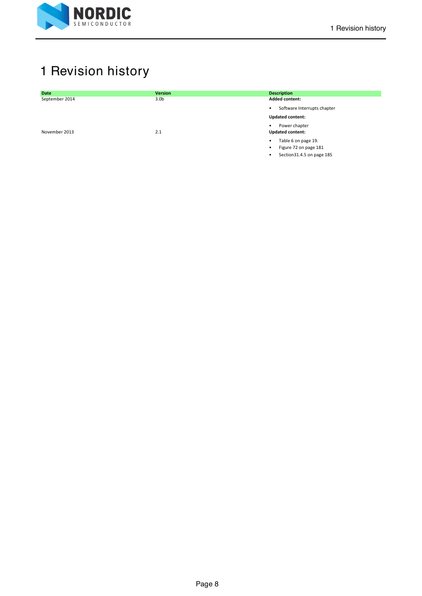
1 Revision history Description Added content: • Updated content: • Updated content: • • • Power chapter Software Interrupts chapter Table 6 on page 19. Figure 72 on page 181 Section31.4.5 on page 185 1 Revision history Date September 2014 November 2013 Version 3.0b 2.1 Page 8
分享到:
收藏