HX1001
HX3001
SSyynncchhrroonnoouuss BBoooosstt DDCC//DDCC RReegguullaattoorr
FFeeaattuurreess
DDeessccrriippttiioonn
�
�
�
�
�
�
�
�
�
�
�
�
�
�
�
�
①
②
fixed
The HX3001 is high efficiency synchronous,
PWM step-up DC/DC converters optimized to
provide a high efficient solution to medium
power systems. The devices work under the
input voltage between 0.9V and 4.4V with a
1.4MHz
frequency switching. These
features minimize overall solution footprint by
allowing the use of tiny, low profile inductors
and ceramic capacitors. Automatic PWM/PFM
mode switching at light load saves power and
improves efficiency.
The HX3001 is capable of supplying an output
voltage between 2.5V and 4.3V, the internal
synchronous switch is desired to provide high
efficiency without Schottky.
The devices also featured providing up to
260mA from a single AA cell input or up to
600mA from a 2-cell AA with a 3V/3.3V output.
The HX3001 regulators are available in the
industry standard SOT-23-6 power packages
(or upon request).
Up to 94% Efficiency
Low voltage start-up
Shut-down current: < 1
Output voltage
Input voltage
0.9V
2.5V
0.9V
A
4.4V
4.3V (Up to 5V with
Low switch on resistance RDS(ON), Internal
Schottky)
switch: 0.35
1.4MHz fixed frequency switching
Automatic PWM/PFM mode switching
High switch on current: 0.9A
Low profile SOT-23-6 package (lead-free
packaging is now available)
:
µ
~
~
:
:
Ω
AApppplliiccaattiioonnss
Digital cameras and MP3
Palmtop computers / PDAs
Cellular phones
Wireless handsets and DSL modems
PC cards
Portable media players
OOrrddeerr IInnffoorrmmaattiioonn
HX3001 -
SYMBOL
②
DESCRIPTION
Denotes Output voltage:
A : Adjustable Output
Denotes Package Types:
F: SOT-23-6
①
www.szkingfrom.com TEL:13923795851 hong
1
Free Datasheet http://www.datasheet4u.com/�
HHXX33000011
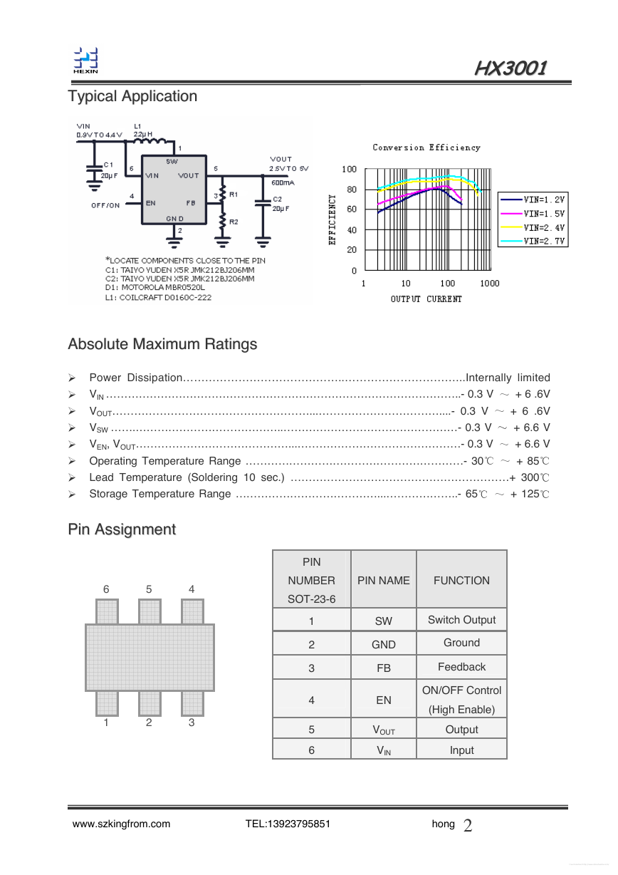
TTyyppiiccaall AApppplliiccaattiioonn
AAbbssoolluuttee MMaaxxiimmuumm RRaattiinnggss
Power Dissipation……………………………………..…………………………...Internally limited
VIN ……………………………………………………………………………………..- 0.3 V
+ 6 .6V
+ 6 .6V
VOUT………………………………………………...……………………………....- 0.3 V
+ 6.6 V
VSW …….…………………………………..…………………………………………- 0.3 V
VEN, VOUT……………………………………...………………………………………- 0.3 V
+ 6.6 V
Operating Temperature Range ……………………………………………………- 30
+ 85
Lead Temperature (Soldering 10 sec.) ……………………………………………………+ 300
Storage Temperature Range …………………………………...………………..- 65
+ 125
~
~
~
~
℃~
℃~
℃
℃
℃
�
�
�
�
�
�
�
�
5
6
PPiinn AAssssiiggnnmmeenntt
1
2
4
3
PIN
NUMBER
SOT-23-6
PIN NAME
1
2
3
4
5
6
SW
GND
FB
EN
VOUT
VIN
FUNCTION
Switch Output
Ground
Feedback
ON/OFF Control
(High Enable)
Output
Input
www.szkingfrom.com TEL:13923795851 hong
2
Free Datasheet http://www.datasheet4u.com/�
HHXX33000011
EElleeccttrriiccaall CChhaarraacctteerriissttiiccss
IN=1.2V, VOUT=3.3V unless otherwise specified.
CONDITIONS
MIN
TYP MAX UNITS
Operating Conditions: TA=25 , V
℃
PARAMETER
Output Voltage Range (Adj.)
Minimum Start-Up Voltage
Minimum Operating Voltage
ILOAD = 1mA
EN = VIN
Switching Frequency
Max Duty Cycle
VFB = 1.15V
Current Limit Delay to Output
Feedback Voltage
Feedback Input Current
VFB = 1.22V
NMOS Switch Leakage
PMOS Switch Leakage
VSW = 5V
VSW = 0V
NMOS Switch On Resistance
VOUT = 3.3V
PMOS Switch On Resistance
VOUT = 3.3V
NMOS Current Limit
700
950
Quiescent Current (Active)
Shutdown Current
En Input High
En Input Low
Measured On VOUT, No
switching
VEN=0V,
Including Switch
Leakage
En Input Current
VEN = 5.5V
1
260
0.1
0.01
1
www.szkingfrom.com TEL:13923795851 hong
3
5
1.1
0.75
V
V
V
1.7
MHz
2.5
1.1
80
0.9
0.6
1.4
87
40
1
0.1
0.1
0.35
0.45
1.165 1.212
1.241
5
5
1
0.35
%
ns
V
nA
A
A
mA
A
A
V
V
A
µ
µ
Ω
Ω
µ
µ
µ
Free Datasheet http://www.datasheet4u.com/�
HHXX33000011
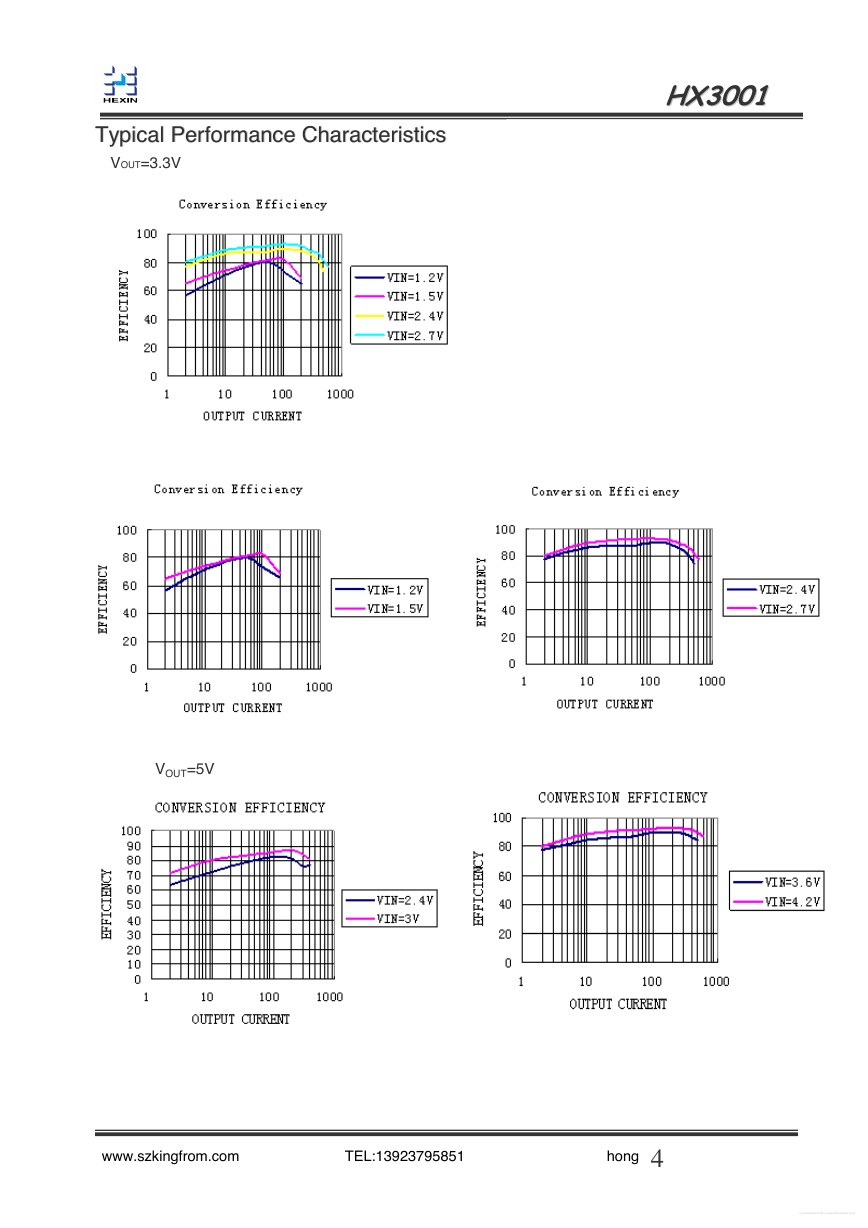
TTyyppiiccaall PPeerrffoorrmmaannccee CChhaarraacctteerriissttiiccss
VOUT=3.3V
VOUT=5V
www.szkingfrom.com TEL:13923795851 hong
4
Free Datasheet http://www.datasheet4u.com/�
HHXX33000011
AApppplliiccaattiioonn IInnffoorrmmaattiioonn
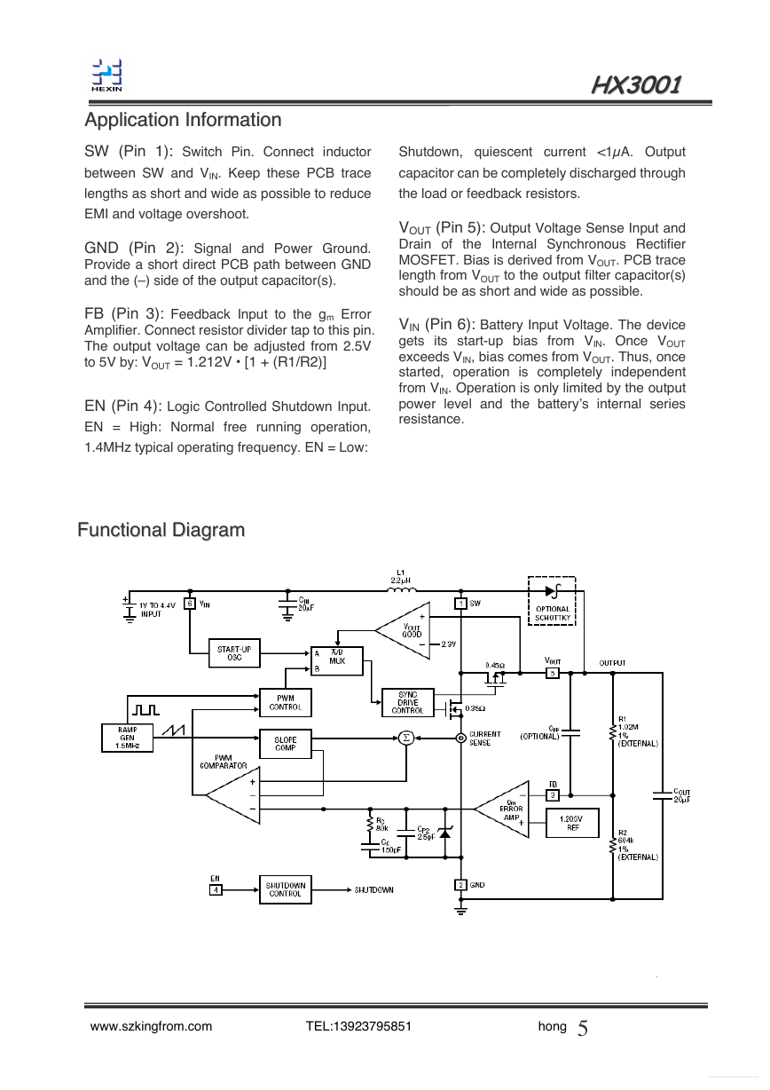
SW (Pin 1): Switch Pin. Connect inductor
between SW and VIN. Keep these PCB trace
lengths as short and wide as possible to reduce
EMI and voltage overshoot.
GND (Pin 2): Signal and Power Ground.
Provide a short direct PCB path between GND
and the (–) side of the output capacitor(s).
FB (Pin 3): Feedback Input to the gm Error
Amplifier. Connect resistor divider tap to this pin.
The output voltage can be adjusted from 2.5V
to 5V by: VOUT = 1.212V • [1 + (R1/R2)]
EN (Pin 4): Logic Controlled Shutdown Input.
EN = High: Normal free running operation,
1.4MHz typical operating frequency. EN = Low:
Shutdown, quiescent current <1µA. Output
capacitor can be completely discharged through
the load or feedback resistors.
VOUT (Pin 5): Output Voltage Sense Input and
Drain of the Internal Synchronous Rectifier
MOSFET. Bias is derived from VOUT. PCB trace
length from VOUT to the output filter capacitor(s)
should be as short and wide as possible.
VIN (Pin 6): Battery Input Voltage. The device
gets its start-up bias from VIN. Once VOUT
exceeds VIN, bias comes from VOUT. Thus, once
started, operation is completely independent
from VIN. Operation is only limited by the output
power level and the battery’s internal series
resistance.
FFuunnccttiioonnaall DDiiaaggrraamm
www.szkingfrom.com TEL:13923795851 hong
.
5
Free Datasheet http://www.datasheet4u.com/�
HHXX33000011
PPaacckkaaggiinngg IInnffoorrmmaattiioonn
Dimensions In Millimeters
Max
Min
1.050
1.250
0.100
0.000
1.150
1.050
0.300
0.500
0.200
0.100
3.020
2.820
1.500
1.700
2.950
2.650
0.950(BSC)
1.800
0.300
0°
2.000
0.600
8°
Dimensions In Inches
Max
0.049
0.004
0.045
0.020
0.008
0.119
0.067
0.116
Min
0.041
0.000
0.041
0.012
0.004
0.111
0.059
0.104
0.037(BSC)
0.071
0.012
0°
0.079
0.024
8°
Symbol
A
A1
A2
b
c
D
E
E1
e
e1
L
θ
.
www.szkingfrom.com TEL:13923795851 hong
6
Free Datasheet http://www.datasheet4u.com/�


 2023年江西萍乡中考道德与法治真题及答案.doc
 2012年重庆南川中考生物真题及答案.doc
 2013年江西师范大学地理学综合及文艺理论基础考研真题.doc
 2020年四川甘孜小升初语文真题及答案I卷.doc
 2020年注册岩土工程师专业基础考试真题及答案.doc
 2023-2024学年福建省厦门市九年级上学期数学月考试题及答案.doc
 2021-2022学年辽宁省沈阳市大东区九年级上学期语文期末试题及答案.doc
 2022-2023学年北京东城区初三第一学期物理期末试卷及答案.doc
 2018上半年江西教师资格初中地理学科知识与教学能力真题及答案.doc
 2012年河北国家公务员申论考试真题及答案-省级.doc
 2020-2021学年江苏省扬州市江都区邵樊片九年级上学期数学第一次质量检测试题及答案.doc
 2022下半年黑龙江教师资格证中学综合素质真题及答案.doc