Rep. ITU-R M.2135
1
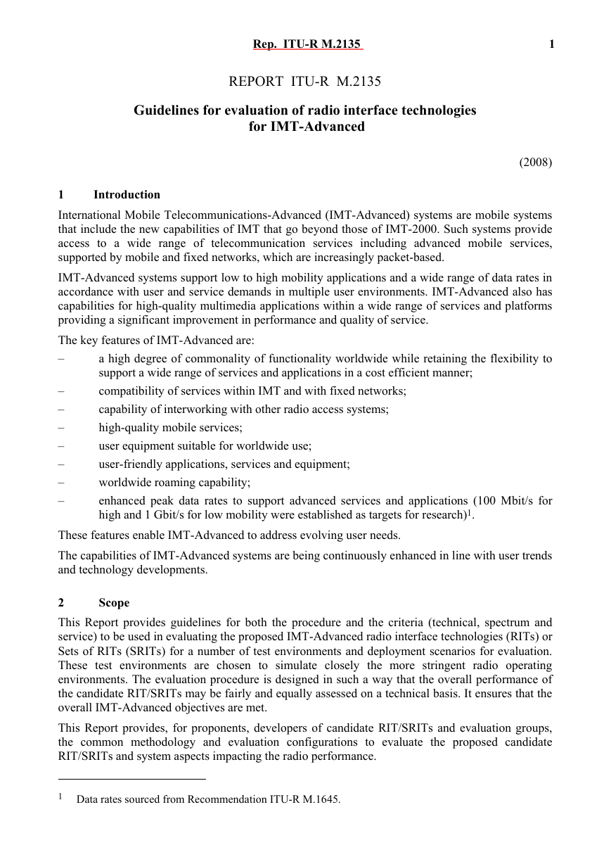
REPORT ITU-R M.2135
Guidelines for evaluation of radio interface technologies
for IMT-Advanced
(2008)
Introduction
1
International Mobile Telecommunications-Advanced (IMT-Advanced) systems are mobile systems
that include the new capabilities of IMT that go beyond those of IMT-2000. Such systems provide
access to a wide range of telecommunication services including advanced mobile services,
supported by mobile and fixed networks, which are increasingly packet-based.
IMT-Advanced systems support low to high mobility applications and a wide range of data rates in
accordance with user and service demands in multiple user environments. IMT-Advanced also has
capabilities for high-quality multimedia applications within a wide range of services and platforms
providing a significant improvement in performance and quality of service.
The key features of IMT-Advanced are:
–
a high degree of commonality of functionality worldwide while retaining the flexibility to
support a wide range of services and applications in a cost efficient manner;
compatibility of services within IMT and with fixed networks;
capability of interworking with other radio access systems;
high-quality mobile services;
user equipment suitable for worldwide use;
user-friendly applications, services and equipment;
worldwide roaming capability;
enhanced peak data rates to support advanced services and applications (100 Mbit/s for
high and 1 Gbit/s for low mobility were established as targets for research)1.
–
–
–
–
–
–
–
These features enable IMT-Advanced to address evolving user needs.
The capabilities of IMT-Advanced systems are being continuously enhanced in line with user trends
and technology developments.
Scope
2
This Report provides guidelines for both the procedure and the criteria (technical, spectrum and
service) to be used in evaluating the proposed IMT-Advanced radio interface technologies (RITs) or
Sets of RITs (SRITs) for a number of test environments and deployment scenarios for evaluation.
These test environments are chosen to simulate closely the more stringent radio operating
environments. The evaluation procedure is designed in such a way that the overall performance of
the candidate RIT/SRITs may be fairly and equally assessed on a technical basis. It ensures that the
overall IMT-Advanced objectives are met.
This Report provides, for proponents, developers of candidate RIT/SRITs and evaluation groups,
the common methodology and evaluation configurations to evaluate the proposed candidate
RIT/SRITs and system aspects impacting the radio performance.
1 Data rates sourced from Recommendation ITU-R M.1645.
�
2
Rep. ITU-R M.2135
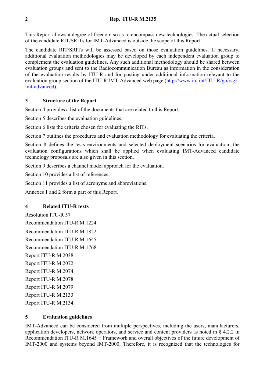
This Report allows a degree of freedom so as to encompass new technologies. The actual selection
of the candidate RIT/SRITs for IMT-Advanced is outside the scope of this Report.
The candidate RIT/SRITs will be assessed based on those evaluation guidelines. If necessary,
additional evaluation methodologies may be developed by each independent evaluation group to
complement the evaluation guidelines. Any such additional methodology should be shared between
evaluation groups and sent to the Radiocommunication Bureau as information in the consideration
of the evaluation results by ITU-R and for posting under additional information relevant to the
evaluation group section of the ITU-R IMT-Advanced web page (http://www.itu.int/ITU-R/go/rsg5-
imt-advanced).
Structure of the Report
3
Section 4 provides a list of the documents that are related to this Report.
Section 5 describes the evaluation guidelines.
Section 6 lists the criteria chosen for evaluating the RITs.
Section 7 outlines the procedures and evaluation methodology for evaluating the criteria.
Section 8 defines the tests environments and selected deployment scenarios for evaluation; the
evaluation configurations which shall be applied when evaluating IMT-Advanced candidate
technology proposals are also given in this section.
Section 9 describes a channel model approach for the evaluation.
Section 10 provides a list of references.
Section 11 provides a list of acronyms and abbreviations.
Annexes 1 and 2 form a part of this Report.
Related ITU-R texts
4
Resolution ITU-R 57
Recommendation ITU-R M.1224
Recommendation ITU-R M.1822
Recommendation ITU-R M.1645
Recommendation ITU-R M.1768
Report ITU-R M.2038
Report ITU-R M.2072
Report ITU-R M.2074
Report ITU-R M.2078
Report ITU-R M.2079
Report ITU-R M.2133
Report ITU-R M.2134.
Evaluation guidelines
5
IMT-Advanced can be considered from multiple perspectives, including the users, manufacturers,
application developers, network operators, and service and content providers as noted in § 4.2.2 in
Recommendation ITU-R M.1645 − Framework and overall objectives of the future development of
IMT-2000 and systems beyond IMT-2000. Therefore, it is recognized that the technologies for
�
Rep. ITU-R M.2135
3
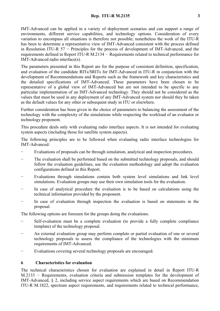
IMT-Advanced can be applied in a variety of deployment scenarios and can support a range of
environments, different service capabilities, and technology options. Consideration of every
variation to encompass all situations is therefore not possible; nonetheless the work of the ITU-R
has been to determine a representative view of IMT-Advanced consistent with the process defined
in Resolution ITU-R 57 − Principles for the process of development of IMT-Advanced, and the
requirements defined in Report ITU-R M.2134 − Requirements related to technical performance for
IMT-Advanced radio interface(s).
The parameters presented in this Report are for the purpose of consistent definition, specification,
and evaluation of the candidate RITs/SRITs for IMT-Advanced in ITU-R in conjunction with the
development of Recommendations and Reports such as the framework and key characteristics and
the detailed specifications of IMT-Advanced. These parameters have been chosen to be
representative of a global view of IMT-Advanced but are not intended to be specific to any
particular implementation of an IMT-Advanced technology. They should not be considered as the
values that must be used in any deployment of any IMT-Advanced system nor should they be taken
as the default values for any other or subsequent study in ITU or elsewhere.
Further consideration has been given in the choice of parameters to balancing the assessment of the
technology with the complexity of the simulations while respecting the workload of an evaluator or
technology proponent.
This procedure deals only with evaluating radio interface aspects. It is not intended for evaluating
system aspects (including those for satellite system aspects).
The following principles are to be followed when evaluating radio interface technologies for
IMT-Advanced:
−
−
Evaluations of proposals can be through simulation, analytical and inspection procedures.
The evaluation shall be performed based on the submitted technology proposals, and should
follow the evaluation guidelines, use the evaluation methodology and adopt the evaluation
configurations defined in this Report.
Evaluations through simulations contain both system level simulations and link level
simulations. Evaluation groups may use their own simulation tools for the evaluation.
In case of analytical procedure the evaluation is to be based on calculations using the
technical information provided by the proponent.
In case of evaluation through inspection the evaluation is based on statements in the
proposal.
−
−
−
The following options are foreseen for the groups doing the evaluations.
−
Self-evaluation must be a complete evaluation (to provide a fully complete compliance
template) of the technology proposal.
An external evaluation group may perform complete or partial evaluation of one or several
technology proposals to assess the compliance of the technologies with the minimum
requirements of IMT-Advanced.
Evaluations covering several technology proposals are encouraged.
−
−
Characteristics for evaluation
6
The technical characteristics chosen for evaluation are explained in detail in Report ITU-R
M.2133 − Requirements, evaluation criteria and submission templates for the development of
IMT-Advanced, § 2, including service aspect requirements which are based on Recommendation
ITU-R M.1822, spectrum aspect requirements, and requirements related to technical performance,
�
4
Rep. ITU-R M.2135
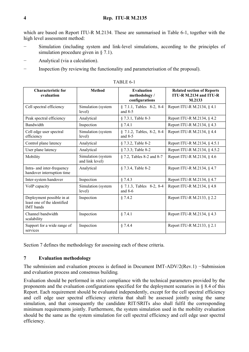
which are based on Report ITU-R M.2134. These are summarised in Table 6-1, together with the
high level assessment method:
−
Simulation (including system and link-level simulations, according to the principles of
simulation procedure given in § 7.1).
Analytical (via a calculation).
Inspection (by reviewing the functionality and parameterisation of the proposal).
−
−
TABLE 6-1
Characteristic for
evaluation
Method
Evaluation
methodology /
configurations
Related section of Reports
ITU-R M.2134 and ITU-R
M.2133
Cell spectral efficiency
Peak spectral efficiency
Bandwidth
Cell edge user spectral
efficiency
Control plane latency
User plane latency
Mobility
Intra- and inter-frequency
handover interruption time
Inter-system handover
VoIP capacity
Deployment possible in at
least one of the identified
IMT bands
Channel bandwidth
scalability
Support for a wide range of
services
Simulation (system
level)
Analytical
Inspection
Simulation (system
level)
Analytical
Analytical
Simulation (system
and link level)
Analytical
Report ITU-R M.2134, § 4.1
§ 7.1.1, Tables 8-2, 8-4
and 8-5
§ 7.3.1, Table 8-3
§ 7.4.1
§ 7.1.2, Tables, 8-2, 8-4
and 8-5
§ 7.3.2, Table 8-2
§ 7.3.3; Table 8-2
§ 7.2, Tables 8-2 and 8-7 Report ITU-R M.2134, § 4.6
Report ITU-R M.2134, § 4.2
Report ITU-R M.2134, § 4.3
Report ITU-R M.2134, § 4.4
Report ITU-R M.2134, § 4.5.1
Report ITU-R M.2134, § 4.5.2
§ 7.3.4, Table 8-2
Report ITU-R M.2134, § 4.7
Inspection
Simulation (system
level)
Inspection
§ 7.4.3
§ 7.1.3, Tables 8-2, 8-4
and 8-6
§ 7.4.2
Report ITU-R M.2134, § 4.7
Report ITU-R M.2134, § 4.8
Report ITU-R M.2133, § 2.2
Inspection
Inspection
§ 7.4.1
§ 7.4.4
Report ITU-R M.2134, § 4.3
Report ITU-R M.2133, § 2.1
Section 7 defines the methodology for assessing each of these criteria.
Evaluation methodology
7
The submission and evaluation process is defined in Document IMT-ADV/2(Rev.1) −Submission
and evaluation process and consensus building.
Evaluation should be performed in strict compliance with the technical parameters provided by the
proponents and the evaluation configurations specified for the deployment scenarios in § 8.4 of this
Report. Each requirement should be evaluated independently, except for the cell spectral efficiency
and cell edge user spectral efficiency criteria that shall be assessed jointly using the same
simulation, and that consequently the candidate RIT/SRITs also shall fulfil the corresponding
minimum requirements jointly. Furthermore, the system simulation used in the mobility evaluation
should be the same as the system simulation for cell spectral efficiency and cell edge user spectral
efficiency.
�
Rep. ITU-R M.2135
5
The evaluation methodology should include the following elements:
1
Candidate RIT/SRITs should be evaluated using reproducible methods including computer
simulation, analytical approaches and inspection of the proposal.
Technical evaluation of the candidate RIT/SRITs should be made against each evaluation
criterion for the required test environments.
Candidate RIT/SRITs should be evaluated based on technical descriptions that are submitted
using a technologies description template.
2
3
In order to have a good comparability of the evaluation results for each proposal, the following
solutions and enablers are to be taken into account:
−
Use of unified methodology, software, and data sets by the evaluation groups wherever
possible, e.g. in the area of channel modelling, link-level data, and link-to-system-level
interface.
Evaluation of multiple proposals using one simulation tool by each evaluation group is
encouraged.
Question-oriented working method that adapts the level of detail in modelling of specific
functionalities according to the particular requirements of the actual investigation.
−
−
Evaluation of cell spectral efficiency, peak spectral efficiency, cell edge user spectral efficiency and
VoIP capacity of candidate RIT/SRITs should take into account the Layer 1 and Layer 2 overhead
information provided by the proponents, which may vary when evaluating different performance
metrics and deployment scenarios.
System simulation procedures
7.1
System simulation shall be based on the network layout defined in § 8.3 of this Report. The
following principles shall be followed in system simulation:
−
Users are dropped independently with uniform distribution over predefined area of the
network layout throughout the system. Each mobile corresponds to an active user session
that runs for the duration of the drop.
Mobiles are randomly assigned LoS and NLoS channel conditions.
Cell assignment to a user is based on the proponent’s cell selection scheme, which must be
described by the proponent.
The minimum distance between a user and a base station is defined in Table 8-2 in § 8.4 of
this Report.
Fading signal and fading interference are computed from each mobile station into each cell
and from each cell into each mobile station (in both directions on an aggregated basis).
The IoT 2 (interference over thermal) parameter is an uplink design constraint that the
proponent must take into account when designing the system such that the average IoT value
experienced in the evaluation is equal to or less than 10 dB.
In simulations based on the full-buffer traffic model, packets are not blocked when they
arrive into the system (i.e. queue depths are assumed to be infinite).
−
−
−
−
−
−
−
Users with a required traffic class shall be modelled according to the traffic models defined
in Annex 2.
2 The interference means the effective interference received at the base station.
�
6
−
Rep. ITU-R M.2135
Packets are scheduled with an appropriate packet scheduler(s) proposed by the proponents
for full buffer and VoIP traffic models separately. Channel quality feedback delay, feedback
errors, PDU (protocol data unit) errors and real channel estimation effects inclusive of
channel estimation error are modelled and packets are retransmitted as necessary.
−
The overhead channels (i.e., the overhead due to feedback and control channels) should be
−
−
realistically modelled.
For a given drop the simulation is run and then the process is repeated with the users
dropped at new random locations. A sufficient number of drops are simulated to ensure
convergence in the user and system performance metrics. The proponent should provide
information on the width of confidence intervals of user and system performance metrics of
corresponding mean values, and evaluation groups are encouraged to provide this
information.3
Performance statistics are collected taking into account the wrap-around configuration in the
network layout, noting that wrap-around is not considered in the indoor case.
−
All cells in the system shall be simulated with dynamic channel properties using a wrap-
around technique, noting that wrap-around is not considered in the indoor case.
In order to perform less complex system simulations, often the simulations are divided into separate
‘link’ and ‘system’ simulations with a specific link-to-system interface. Another possible way to
reduce system simulation complexity is to employ simplified interference modelling. Such methods
should be sound in principle, and it is not within the scope of this document to describe them.
Evaluation groups are allowed to use such approaches provided that the used methodologies are:
−
well described and made available to the Radiocommunication Bureau and other evaluation
groups;
included in the evaluation report.
−
Realistic link and system models should include error modelling, e.g., for channel estimation and
for the errors of control channels that are required to decode the traffic channel (including the
feedback channel and channel quality information). The overheads of the feedback channel and the
control channel should be modelled according to the assumptions used in the overhead channels’
radio resource allocation.
7.1.1 Cell spectral efficiency
The results from the system simulation are used to calculate the cell spectral efficiency as defined in
Report ITU-R M.2134, § 4.1. The necessary information includes the number of correctly received
bits during the simulation period and the effective bandwidth which is the operating bandwidth
normalised appropriately considering the uplink/downlink ratio for TDD system.
Layer 1 and Layer 2 overhead should be accounted for in time and frequency for the purpose of
calculation of system performance metrics such as cell spectral efficiency, cell edge user spectral
efficiency, and VoIP. Examples of Layer 1 overhead include synchronization, guard and DC
subcarriers, guard/switching time (in TDD systems), pilots and cyclic prefix. Examples of Layer 2
overhead include common control channels, HARQ ACK/NACK signalling, channel feedback,
random access, packet headers and CRC. It must be noted that in computing the overheads, the
fraction of the available physical resources used to model control overhead in Layer 1 and Layer 2
3 The confidence interval and the associated confidence level indicate the reliability of the estimated
parameter value. The confidence level is the certainty (probability) that the true parameter value is within
the confidence interval. The higher the confidence level the larger the confidence interval.
�
Rep. ITU-R M.2135
7
should be accounted for in a non-overlapping way. Power allocation/boosting should also be
accounted for in modelling resource allocation for control channels.
7.1.2 Cell edge user spectral efficiency
The results from the system simulation are used to calculate the cell edge user spectral efficiency as
defined in Report ITU-R M.2134, § 4.4. The necessary information is the number of correctly
received bits per user during the active session time the user is in the simulation. The effective
bandwidth is the operating bandwidth normalised appropriately considering the uplink/downlink
ratio for TDD system. It should be noted that the cell edge user spectral efficiency shall be
evaluated using identical simulation assumptions as the cell spectral efficiency for that test
environment.
Examples of Layer 1 and Layer 2 overhead can be found in § 7.1.1.
7.1.3 VoIP capacity
The VoIP capacity should be evaluated and compared against the requirements in Report
ITU-R M.2134, § 4.8.
VoIP capacity should be evaluated for the uplink and downlink directions assuming a 12.2 kbit/s
codec with a 50% activity factor such that the percentage of users in outage is less than 2%, where a
user is defined to have experienced a voice outage if less than 98% of the VoIP packets have been
delivered successfully to the user within a permissible VoIP packet delay bound of 50 ms. The
VoIP packet delay is the overall latency from the source coding at the transmitter to successful
source decoding at the receiver.
The final VoIP capacity which is to be compared against the requirements in Report ITU-R M.2134
is the minimum of the calculated capacity for either link direction divided by the effective
bandwidth in the respective link direction4.
The simulation is run with the duration for a given drop defined in Table 8-6 of this Report. The
VoIP traffic model is defined in Annex 2.
Evaluation methodology for mobility requirements
7.2
The evaluator shall perform the following steps in order to evaluate the mobility requirement.
Step 1: Run system simulations, identical to those for cell spectral efficiencies, see § 7.1.1 except
for speeds taken from Table 4 of Report ITU-R M.2134, using link level simulations and a link-to-
system interface appropriate for these speed values, for the set of selected test environment(s)
associated with the candidate RIT/SRIT proposal and collect overall statistics for uplink C/I values,
and construct cumulative distribution function (CDF) over these values for each test environment.
Step 2: Use the CDF for the test environment(s) to save the respective 50%-percentile C/I value.
Step 3: Run new uplink link-level simulations for the selected test environment(s) for both NLoS
and LoS channel conditions using the associated speeds in Table 4 of Report ITU-R M.2134, § 4.6
as input parameters, to obtain link data rate and residual packet error rate as a function of C/I. The
link-level simulation shall use air interface configuration(s) supported by the proposal and take into
account retransmission.
Step 4: Compare the link spectral efficiency values (link data rate normalized by channel
bandwidth) obtained from Step 3 using the associated C/I value obtained from Step 2 for each
4
In other words, the effective bandwidth is the operating bandwidth normalised appropriately considering
the uplink/downlink ratio for TDD systems.
�
8
Rep. ITU-R M.2135
channel model case, with the corresponding threshold values in the Table 4 of Report ITU-R
M.2134, § 4.6.
Step 5: The proposal fulfils the mobility requirement if the spectral efficiency value is larger than
or equal to the corresponding threshold value and if also the residual decoded packet error rate is
less than 1%, for all selected test environments. For each test environment it is sufficient if one of
the spectral efficiency values (of either NLoS or LoS channel conditions) fulfil the threshold.
Analytical approach
7.3
For the characteristics below a straight forward calculation based on the definition in Report
ITU-R M.2134 and information in the proposal will be enough to evaluate them. The evaluation
shall describe how this calculation has been performed. Evaluation groups should follow the
calculation provided by proponents if it is justified properly.
7.3.1 Peak spectral efficiency calculation
The peak spectral efficiency is calculated as specified in Report ITU-R M.2134 § 4.2. The antenna
configuration to be used for peak spectral efficiency is defined in Table 8-3 of this Report. The
necessary information includes effective bandwidth which is the operating bandwidth normalised
appropriately considering the uplink/downlink ratio for TDD systems. Examples of Layer 1
overhead can be found in § 7.1.1.
7.3.2 Control plane latency calculation
The control plane latency is calculated as specified in Report ITU-R M.2134, § 4.5.1.
The proponent should provide the elements in the calculation of the control plane latency and the
retransmission probability.
Table 7-1 provides, for the purpose of example, typical elements in the calculation of the control
plane latency. The inclusion of H-ARQ/ARQ retransmissions in each step of the connection set up
is to ensure the required reliability of connection which typically has a probability of error in the
order of 10−2 for certain Layer 2 control signals and 10−6 for some RRC control signals.
TABLE 7-1
Example C-plane latency template
Step Description
0
1
2
3
4
5
6
7
UT wakeup time
DL scanning and synchronization + Broadcast channel acquisition
Random access procedure
UL synchronization
Capability negotiation + H-ARQ retransmission probability
Authorization and authentication/key exchange +H-ARQ retransmission probability
Registration with the BS + H-ARQ retransmission probability
RRC connection establishment + H-ARQ retransmission probability
Total C-plane connection establishment delay
Total IDLE_STATE –> ACTIVE_ACTIVE delay
Duration
Implementation
dependent
7.3.3 User plane latency calculation
The user plane latency is calculated as specified in Report ITU-R M.2134, § 4.5.2. The proponent
should provide the elements in the calculation of the user plane latency and the retransmission
probability.
�


 2023年江西萍乡中考道德与法治真题及答案.doc
 2012年重庆南川中考生物真题及答案.doc
 2013年江西师范大学地理学综合及文艺理论基础考研真题.doc
 2020年四川甘孜小升初语文真题及答案I卷.doc
 2020年注册岩土工程师专业基础考试真题及答案.doc
 2023-2024学年福建省厦门市九年级上学期数学月考试题及答案.doc
 2021-2022学年辽宁省沈阳市大东区九年级上学期语文期末试题及答案.doc
 2022-2023学年北京东城区初三第一学期物理期末试卷及答案.doc
 2018上半年江西教师资格初中地理学科知识与教学能力真题及答案.doc
 2012年河北国家公务员申论考试真题及答案-省级.doc
 2020-2021学年江苏省扬州市江都区邵樊片九年级上学期数学第一次质量检测试题及答案.doc
 2022下半年黑龙江教师资格证中学综合素质真题及答案.doc