all
调用 LMS 算法
%function main()
close
% 周期信号的产生
t=0:99;
xs=10*sin(0.5*t);
figure;
subplot(2,1,1);
plot(t,xs);grid;
ylabel('幅值');
title('it{输入周期性信号}');
% 噪声信号的产生
randn('state',sum(100*clock));
xn=randn(1,100);
subplot(2,1,2);
plot(t,xn);grid;
ylabel('幅值');
xlabel('时间');
title('it{随机噪声信号}');
% 信号滤波
xn = xs+xn;
xn = xn.' ; % 输入信号序列
dn = xs.' ; % 预期结果序列
M = 20
rho_max = max(eig(xn*xn.')); % 输入信号相关矩阵的最大特征值
mu = rand()*(1/rho_max)
[yn,W,en] = LMS(xn,dn,M,mu);
% 绘制滤波器输入信号
figure;
subplot(2,1,1);
plot(t,xn);grid;
ylabel('幅值');
xlabel('时间');
title('it{滤波器输入信号}');
% 绘制自适应滤波器输出信号
subplot(2,1,2);
plot(t,yn);grid;
ylabel('幅值');
xlabel('时间');
title('it{自适应滤波器输出信号}');
% 绘制自适应滤波器输出信号,预期输出信号和两者的误差
figure
plot(t,yn,'b',t,dn,'g',t,dn-yn,'r');grid;
legend('自适应滤波器输出','预期输出','误差');
% 收敛因子 0 < mu < 1/rho
; % 滤波器的阶数
;
�
//定义阶数 16 阶
//点数
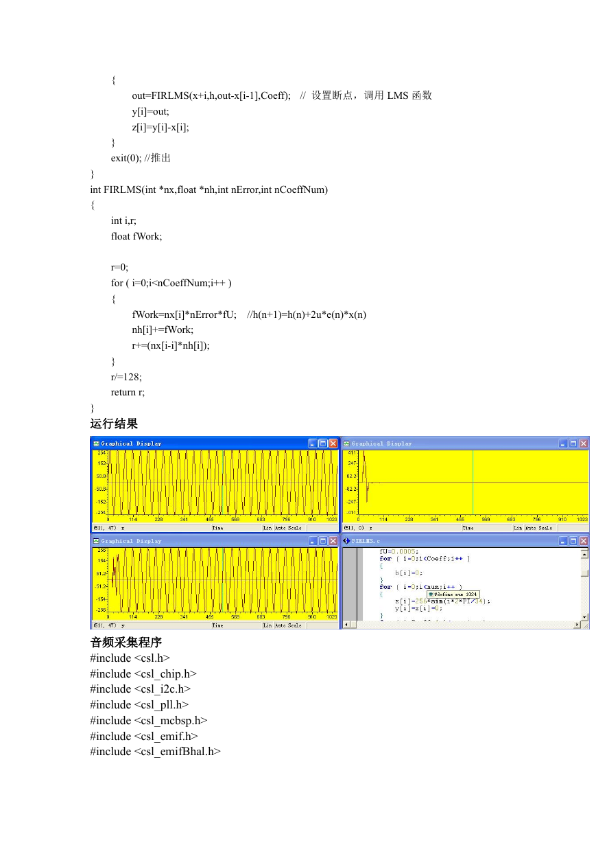
LMS 算法 DSP 程序
#include"math.h"
#define PI 3.1415926
#define Coeff 16
#define num 1024
int FIRLMS(int *nx,float *nh,int nError,int nCoeffNum);
float h[Coeff],fU;
//h 单位脉冲响应 fu---2U 的值
int x[num],y[num],z[num];//x 输入信号,y 输出,z 误差信号
main()
{
//LMS 函数声明
int i,out;
out=0;
fU=0.0005;
for ( i=0;i
{
out=FIRLMS(x+i,h,out-x[i-1],Coeff);
y[i]=out;
z[i]=y[i]-x[i];
}
exit(0); //推出
// 设置断点,调用 LMS 函数
}
int FIRLMS(int *nx,float *nh,int nError,int nCoeffNum)
{
int i,r;
float fWork;
r=0;
for ( i=0;i
#include
#include
#include
#include
#include
#include
�
#include
#include "5502_FLASH.h"
#include "E2PROM_Function.h"
#include "CODEC.h"
#undef CODEC_ADDR
#define CODEC_ADDR 0x1A
Uint16 SourData1[65536]={0};
Uint16 SourData2[65536]={0};
Uint16 SourData3[65536]={0};
Uint16 OutData1[65536]={0};
Uint16 OutData2[65536]={0};
Uint16 OutData3[65536]={0};
#pragma DATA_SECTION (SourData1,".Audio_in_data1");
#pragma DATA_SECTION (SourData2,".Audio_in_data2");
#pragma DATA_SECTION (SourData3,".Audio_in_data3");
#pragma DATA_SECTION (OutData1,".Audio_out_data1");
#pragma DATA_SECTION (OutData2,".Audio_out_data2");
#pragma DATA_SECTION (OutData3,".Audio_out_data3");
// 定义 McBSP 的句柄
MCBSP_Handle hMcbsp;
/*------------------------------------------------------------------------------------*/
//
// FUNCTION: MAIN
//
/*------------------------------------------------------------------------------------*/
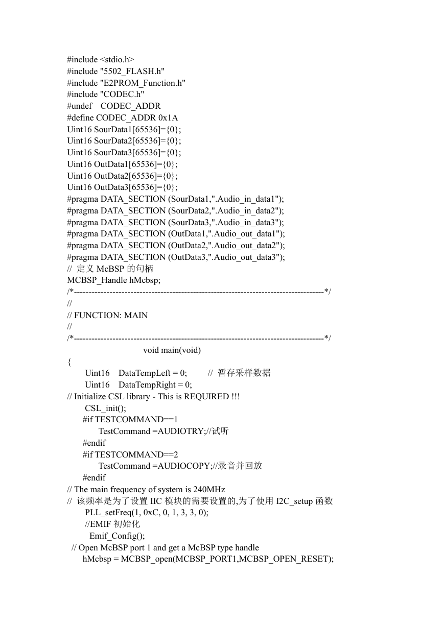
void main(void)
{
Uint16 DataTempLeft = 0;
Uint16 DataTempRight = 0;
// 暂存采样数据
// Initialize CSL library - This is REQUIRED !!!
CSL_init();
#if TESTCOMMAND==1
#endif
#if TESTCOMMAND==2
TestCommand =AUDIOTRY;//试听
TestCommand =AUDIOCOPY;//录音并回放
#endif
// The main frequency of system is 240MHz
// 该频率是为了设置 IIC 模块的需要设置的,为了使用 I2C_setup 函数
PLL_setFreq(1, 0xC, 0, 1, 3, 3, 0);
//EMIF 初始化
Emif_Config();
// Open McBSP port 1 and get a McBSP type handle
hMcbsp = MCBSP_open(MCBSP_PORT1,MCBSP_OPEN_RESET);
�
Mcbsp_Config(hMcbsp);
//I2C 初始化
I2C_cofig();
//CODEC 寄存器初始化
inti_AIC();
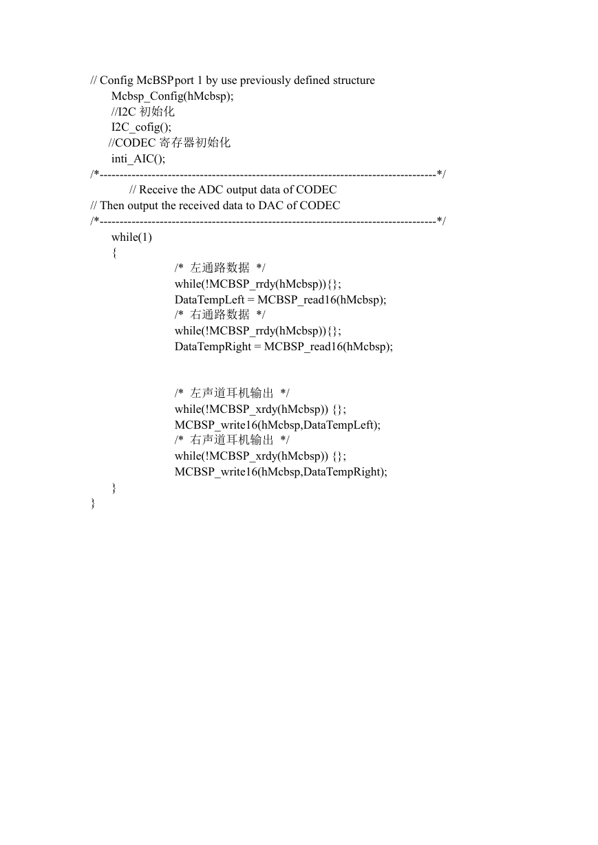
while(1)
{
/*------------------------------------------------------------------------------------*/
// Receive the ADC output data of CODEC
// Then output the received data to DAC of CODEC
/*------------------------------------------------------------------------------------*/
// Config McBSPport 1 by use previously defined structure
/* 左通路数据 */
while(!MCBSP_rrdy(hMcbsp)){};
DataTempLeft = MCBSP_read16(hMcbsp);
/* 右通路数据 */
while(!MCBSP_rrdy(hMcbsp)){};
DataTempRight = MCBSP_read16(hMcbsp);
/* 左声道耳机输出 */
while(!MCBSP_xrdy(hMcbsp)) {};
MCBSP_write16(hMcbsp,DataTempLeft);
/* 右声道耳机输出 */
while(!MCBSP_xrdy(hMcbsp)) {};
MCBSP_write16(hMcbsp,DataTempRight);
}
}
�


 2023年江西萍乡中考道德与法治真题及答案.doc
 2012年重庆南川中考生物真题及答案.doc
 2013年江西师范大学地理学综合及文艺理论基础考研真题.doc
 2020年四川甘孜小升初语文真题及答案I卷.doc
 2020年注册岩土工程师专业基础考试真题及答案.doc
 2023-2024学年福建省厦门市九年级上学期数学月考试题及答案.doc
 2021-2022学年辽宁省沈阳市大东区九年级上学期语文期末试题及答案.doc
 2022-2023学年北京东城区初三第一学期物理期末试卷及答案.doc
 2018上半年江西教师资格初中地理学科知识与教学能力真题及答案.doc
 2012年河北国家公务员申论考试真题及答案-省级.doc
 2020-2021学年江苏省扬州市江都区邵樊片九年级上学期数学第一次质量检测试题及答案.doc
 2022下半年黑龙江教师资格证中学综合素质真题及答案.doc