SURFACE VEHICLE
STANDARD
J1772™
OCT2017
Issued
Revised
Superseding J1772 FEB2016
1996-01
2017-10
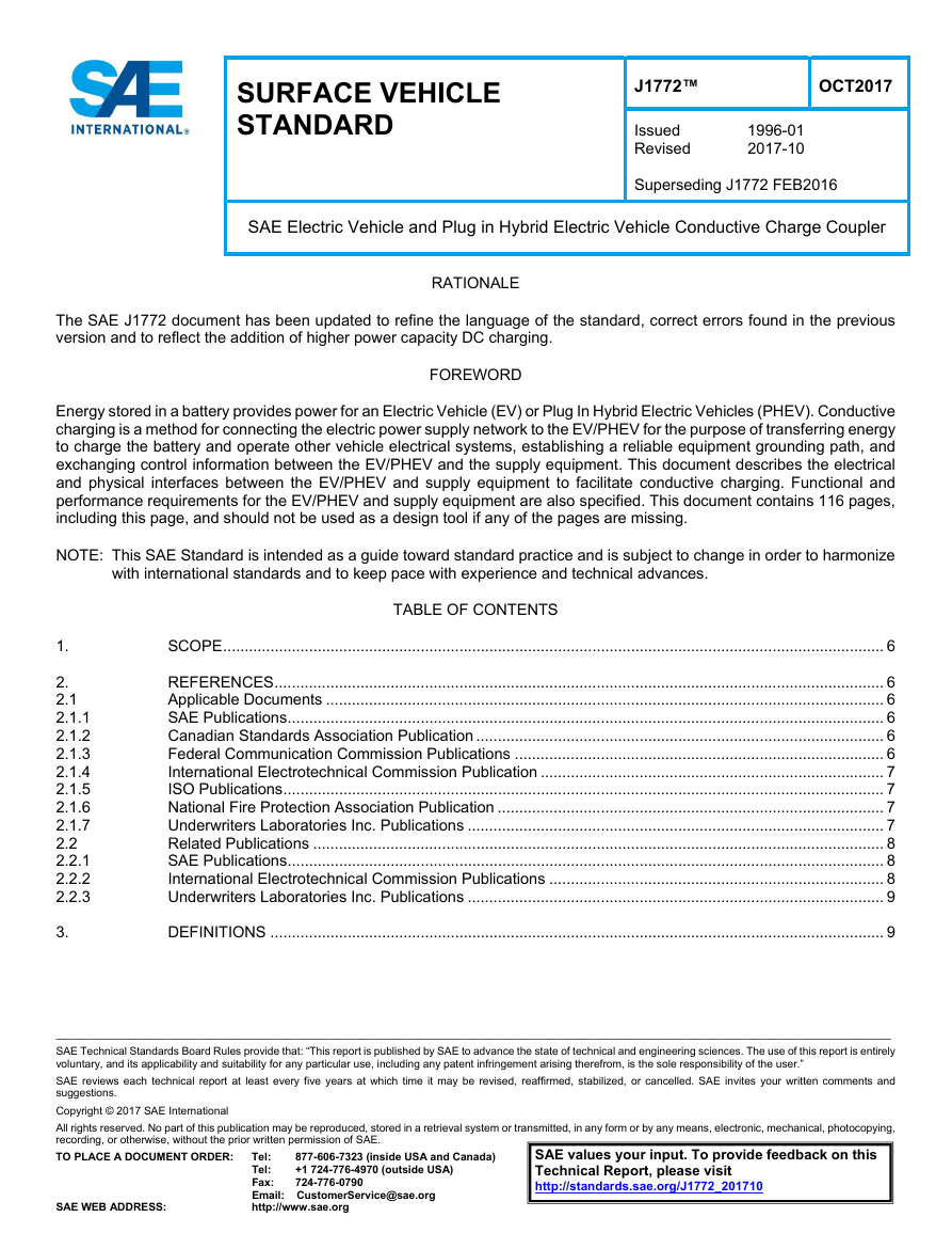
SAE Electric Vehicle and Plug in Hybrid Electric Vehicle Conductive Charge Coupler
RATIONALE
The SAE J1772 document has been updated to refine the language of the standard, correct errors found in the previous
version and to reflect the addition of higher power capacity DC charging.
FOREWORD
Energy stored in a battery provides power for an Electric Vehicle (EV) or Plug In Hybrid Electric Vehicles (PHEV). Conductive
charging is a method for connecting the electric power supply network to the EV/PHEV for the purpose of transferring energy
to charge the battery and operate other vehicle electrical systems, establishing a reliable equipment grounding path, and
exchanging control information between the EV/PHEV and the supply equipment. This document describes the electrical
and physical interfaces between the EV/PHEV and supply equipment to facilitate conductive charging. Functional and
performance requirements for the EV/PHEV and supply equipment are also specified. This document contains 116 pages,
including this page, and should not be used as a design tool if any of the pages are missing.
NOTE: This SAE Standard is intended as a guide toward standard practice and is subject to change in order to harmonize
with international standards and to keep pace with experience and technical advances.
1.
2.
2.1
2.1.1
2.1.2
2.1.3
2.1.4
2.1.5
2.1.6
2.1.7
2.2
2.2.1
2.2.2
2.2.3
3.
TABLE OF CONTENTS
SCOPE .......................................................................................................................................................... 6
REFERENCES .............................................................................................................................................. 6
Applicable Documents .................................................................................................................................. 6
SAE Publications ........................................................................................................................................... 6
Canadian Standards Association Publication ............................................................................................... 6
Federal Communication Commission Publications ...................................................................................... 6
International Electrotechnical Commission Publication ................................................................................ 7
ISO Publications ............................................................................................................................................ 7
National Fire Protection Association Publication .......................................................................................... 7
Underwriters Laboratories Inc. Publications ................................................................................................. 7
Related Publications ..................................................................................................................................... 8
SAE Publications ........................................................................................................................................... 8
International Electrotechnical Commission Publications .............................................................................. 8
Underwriters Laboratories Inc. Publications ................................................................................................. 9
DEFINITIONS ............................................................................................................................................... 9
__________________________________________________________________________________________________________________________________________
SAE Technical Standards Board Rules provide that: “This report is published by SAE to advance the state of technical and engineering sciences. The use of this report is entirely
voluntary, and its applicability and suitability for any particular use, including any patent infringement arising therefrom, is the sole responsibility of the user.”
SAE reviews each technical report at least every five years at which time it may be revised, reaffirmed, stabilized, or cancelled. SAE invites your written comments and
suggestions.
Copyright © 2017 SAE International
All rights reserved. No part of this publication may be reproduced, stored in a retrieval system or transmitted, in any form or by any means, electronic, mechanical, photocopying,
recording, or otherwise, without the prior written permission of SAE.
TO PLACE A DOCUMENT ORDER:
SAE WEB ADDRESS:
SAE values your input. To provide feedback on this
Technical Report, please visit
http://standards.sae.org/J1772_201710
Tel: 877-606-7323 (inside USA and Canada)
Tel: +1 724-776-4970 (outside USA)
Fax: 724-776-0790
Email: CustomerService@sae.org
http://www.sae.org
�
J1772™ OCT2017
Page 2 of 116
SAE INTERNATIONAL
4.
4.1
4.2
4.2.1
4.2.2
4.3
4.4
4.5
4.5.1
4.5.2
4.5.3
4.6
4.6.1
4.6.2
4.6.3
4.6.4
4.6.5
4.6.6
4.7
4.7.1
4.7.2
4.7.3
4.7.4
4.7.5
4.7.6
4.7.7
4.7.8
4.7.9
4.7.10
4.7.11
4.7.12
4.8
4.8.1
4.8.2
4.8.3
4.8.4
4.8.5
4.8.6
4.8.7
4.8.8
4.8.9
4.9
4.9.1
4.9.2
4.9.3
4.9.4
4.9.5
5.
5.1
5.2
5.2.1
5.2.2
5.3
5.4
5.5
5.5.1
5.5.2
5.6
5.6.1
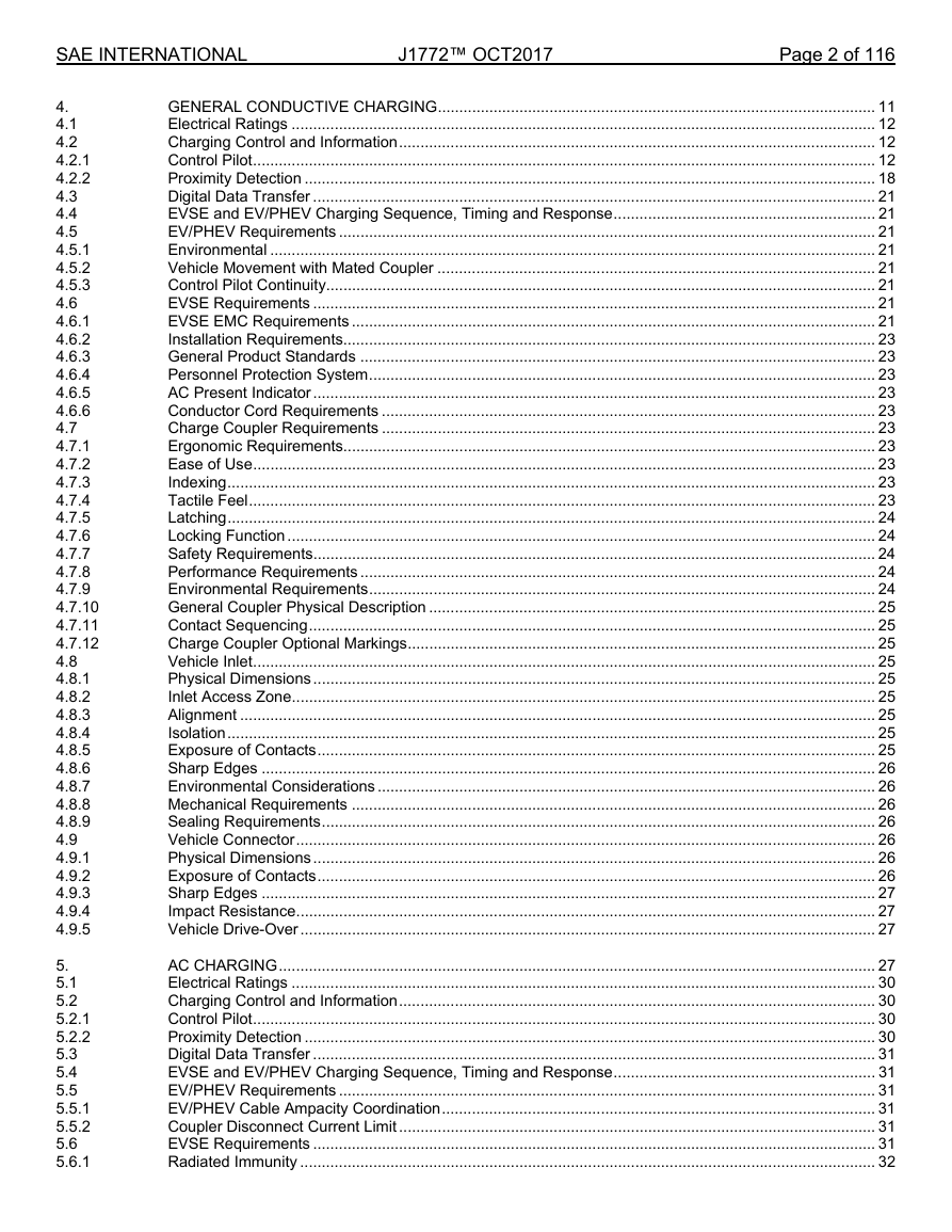
GENERAL CONDUCTIVE CHARGING ...................................................................................................... 11
Electrical Ratings ........................................................................................................................................ 12
Charging Control and Information ............................................................................................................... 12
Control Pilot ................................................................................................................................................. 12
Proximity Detection ..................................................................................................................................... 18
Digital Data Transfer ................................................................................................................................... 21
EVSE and EV/PHEV Charging Sequence, Timing and Response ............................................................. 21
EV/PHEV Requirements ............................................................................................................................. 21
Environmental ............................................................................................................................................. 21
Vehicle Movement with Mated Coupler ...................................................................................................... 21
Control Pilot Continuity ................................................................................................................................ 21
EVSE Requirements ................................................................................................................................... 21
EVSE EMC Requirements .......................................................................................................................... 21
Installation Requirements............................................................................................................................ 23
General Product Standards ........................................................................................................................ 23
Personnel Protection System ...................................................................................................................... 23
AC Present Indicator ................................................................................................................................... 23
Conductor Cord Requirements ................................................................................................................... 23
Charge Coupler Requirements ................................................................................................................... 23
Ergonomic Requirements............................................................................................................................ 23
Ease of Use ................................................................................................................................................. 23
Indexing ....................................................................................................................................................... 23
Tactile Feel .................................................................................................................................................. 23
Latching ....................................................................................................................................................... 24
Locking Function ......................................................................................................................................... 24
Safety Requirements ................................................................................................................................... 24
Performance Requirements ........................................................................................................................ 24
Environmental Requirements ...................................................................................................................... 24
General Coupler Physical Description ........................................................................................................ 25
Contact Sequencing .................................................................................................................................... 25
Charge Coupler Optional Markings ............................................................................................................. 25
Vehicle Inlet ................................................................................................................................................. 25
Physical Dimensions ................................................................................................................................... 25
Inlet Access Zone ........................................................................................................................................ 25
Alignment .................................................................................................................................................... 25
Isolation ....................................................................................................................................................... 25
Exposure of Contacts .................................................................................................................................. 25
Sharp Edges ............................................................................................................................................... 26
Environmental Considerations .................................................................................................................... 26
Mechanical Requirements .......................................................................................................................... 26
Sealing Requirements ................................................................................................................................. 26
Vehicle Connector ....................................................................................................................................... 26
Physical Dimensions ................................................................................................................................... 26
Exposure of Contacts .................................................................................................................................. 26
Sharp Edges ............................................................................................................................................... 27
Impact Resistance ....................................................................................................................................... 27
Vehicle Drive-Over ...................................................................................................................................... 27
AC CHARGING ........................................................................................................................................... 27
Electrical Ratings ........................................................................................................................................ 30
Charging Control and Information ............................................................................................................... 30
Control Pilot ................................................................................................................................................. 30
Proximity Detection ..................................................................................................................................... 30
Digital Data Transfer ................................................................................................................................... 31
EVSE and EV/PHEV Charging Sequence, Timing and Response ............................................................. 31
EV/PHEV Requirements ............................................................................................................................. 31
EV/PHEV Cable Ampacity Coordination ..................................................................................................... 31
Coupler Disconnect Current Limit ............................................................................................................... 31
EVSE Requirements ................................................................................................................................... 31
Radiated Immunity ...................................................................................................................................... 32
�
J1772™ OCT2017
Page 3 of 116
Charge Coupler Requirements ................................................................................................................... 33
Vehicle Inlet ................................................................................................................................................. 33
Vehicle Connector ....................................................................................................................................... 33
SAE INTERNATIONAL
5.7
5.8
5.9
6.
6.1
6.2
6.2.1
6.2.2
6.3
6.3.1
6.4
6.4.1
6.4.2
6.4.3
6.4.4
6.4.5
6.5
6.5.1
6.5.2
6.5.3
6.5.4
6.5.5
6.5.6
6.5.7
6.5.8
6.5.9
6.5.10
6.5.11
6.5.12
6.5.13
6.5.14
6.5.15
6.5.16
6.5.17
6.5.18
6.5.19
6.5.20
6.5.21
6.5.22
6.5.23
6.5.24
6.5.25
6.5.26
6.5.27
6.6
6.6.1
6.6.2
6.7
6.7.1
6.7.2
6.8
6.8.1
6.8.2
6.8.3
7.
7.1
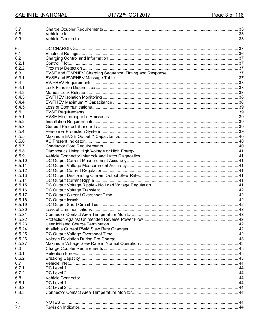
DC CHARGING ........................................................................................................................................... 33
Electrical Ratings ........................................................................................................................................ 36
Charging Control and Information ............................................................................................................... 37
Control Pilot ................................................................................................................................................. 37
Proximity Detection ..................................................................................................................................... 37
EVSE and EV/PHEV Charging Sequence, Timing and Response ............................................................. 37
EVSE and EV/PHEV Message Table ......................................................................................................... 37
EV/PHEV Requirements ............................................................................................................................. 38
Lock Function Diagnostics .......................................................................................................................... 38
Manual Lock Release .................................................................................................................................. 38
EV/PHEV Isolation Monitoring .................................................................................................................... 38
EV/PHEV Maximum Y Capacitance ........................................................................................................... 38
Loss of Communications ............................................................................................................................. 39
EVSE Requirements ................................................................................................................................... 39
EVSE Electromagnetic Emissions .............................................................................................................. 39
Installation Requirements............................................................................................................................ 39
General Product Standards ........................................................................................................................ 39
Personnel Protection System ...................................................................................................................... 39
Maximum EVSE Output Y Capacitance ...................................................................................................... 40
AC Present Indicator ................................................................................................................................... 40
Conductor Cord Requirements ................................................................................................................... 40
Diagnostics Using High Voltage or High Energy ........................................................................................ 41
Vehicle Connector Interlock and Latch Diagnostics ................................................................................... 41
DC Output Current Measurement Accuracy ............................................................................................... 41
DC Output Voltage Measurement Accuracy ............................................................................................... 41
DC Output Current Regulation .................................................................................................................... 41
DC Output Descending Current Output Slew Rate ..................................................................................... 41
DC Output Current Ripple ........................................................................................................................... 41
DC Output Voltage Ripple - No Load Voltage Regulation .......................................................................... 41
DC Output Voltage Transient ...................................................................................................................... 42
DC Output Current Overshoot Time ........................................................................................................... 42
DC Output Inrush ........................................................................................................................................ 42
DC Output Short Circuit Test ...................................................................................................................... 42
Loss of Communications ............................................................................................................................. 42
Connector Contact Area Temperature Monitor ........................................................................................... 42
Protection Against Unintended Reverse Power Flow ................................................................................. 42
User Initiated Charge Termination .............................................................................................................. 42
Available Current PWM Slew Rate Changes .............................................................................................. 42
DC Output Voltage Overshoot Time ........................................................................................................... 42
Voltage Deviation During Pre-Charge ......................................................................................................... 43
Maximum Voltage Slew Rate in Normal Operation .................................................................................... 43
Charge Coupler Requirements ................................................................................................................... 43
Retention Force ........................................................................................................................................... 43
Breaking Capacity ....................................................................................................................................... 43
Vehicle Inlet ................................................................................................................................................. 44
DC Level 1 .................................................................................................................................................. 44
DC Level 2 .................................................................................................................................................. 44
Vehicle Connector ....................................................................................................................................... 44
DC Level 1 .................................................................................................................................................. 44
DC Level 2 .................................................................................................................................................. 44
Connector Contact Area Temperature Monitor ........................................................................................... 44
NOTES ........................................................................................................................................................ 44
Revision Indicator ........................................................................................................................................ 44
�
J1772™ OCT2017
Page 4 of 116
SAE INTERNATIONAL
APPENDIX A CHARGE COUPLER DIMENSIONAL REQUIREMENTS (NON LOCKABLE) ........................................... 45
APPENDIX B CHARGE COUPLER DIMENSIONAL REQUIREMENTS (LOCKABLE) .................................................... 52
APPENDIX C DC LEVEL 2 COUPLER ............................................................................................................................. 55
APPENDIX D VEHICLE INLET LOCK FUNCTION ZONE DEFINITION .......................................................................... 59
APPENDIX E EVSE AND EV/PHEV SEQUENCE AND RESPONSE TIME SPECIFICATIONS ..................................... 60
APPENDIX F DC EVSE AND EV/PHEV SEQUENCE AND RESPONSE TIME SPECIFICATIONS ............................... 67
APPENDIX G MESSAGE TABLE ...................................................................................................................................... 86
APPENDIX H DRAFT COUPLER PERFORMANCE CERTIFICATION TEST PROCEDURES - ..................................... 88
APPENDIX I DC LEVEL 1 AND LEVEL 2 COMBINATIONS FOR PEVS & EVSES - INFORMATIVE ........................... 95
APPENDIX J DC Y CAPACITANCE REQUIREMENT DERIVATION - INFORMATIVE .................................................. 99
APPENDIX K WAKEUP OF CERTAIN LEGACY VEHICLES (INFORMATIVE) ............................................................. 103
APPENDIX L HISTORY EVSE/VEHICLE INTERFACE .................................................................................................. 104
APPENDIX M AC LEVEL 3 CHARGING.......................................................................................................................... 107
APPENDIX N PREVIOUS CHARGE COUPLER DESIGNS ........................................................................................... 110
APPENDIX O COMPATIBILITY BETWEEN HIGH CAPACITY EVSES AND CERTAIN LEGACY VEHICLES………. 114
APPENDIX P MAXIMUM OUTLINE OF LATCH (INFORMATIVE)…………………………………………………………. 115
FIGURE 1
FIGURE 2
FIGURE 3
FIGURE 4
FIGURE 5
FIGURE 6
FIGURE 7
FIGURE 8
FIGURE 9
FIGURE 10
FIGURE 11
FIGURE 12
FIGURE 13
FIGURE 14
FIGURE 15
FIGURE 16
FIGURE 17
FIGURE 18
FIGURE 19
FIGURE 20
FIGURE 21
FIGURE 22
FIGURE 23
FIGURE 24
FIGURE 25
FIGURE 26
FIGURE 27
FIGURE 28
FIGURE 29
FIGURE 30
FIGURE 31
FIGURE 32
FIGURE 33
FIGURE 34
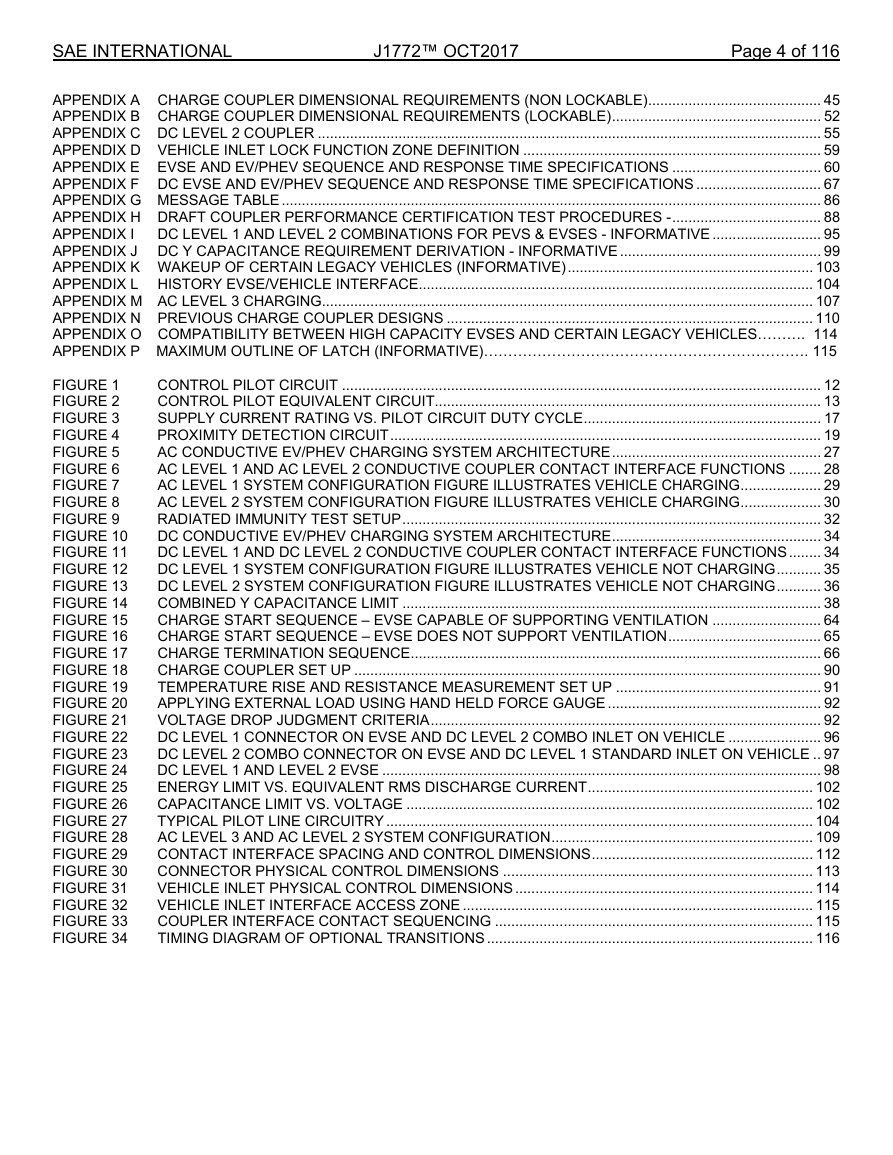
CONTROL PILOT CIRCUIT ....................................................................................................................... 12
CONTROL PILOT EQUIVALENT CIRCUIT ................................................................................................ 13
SUPPLY CURRENT RATING VS. PILOT CIRCUIT DUTY CYCLE ........................................................... 17
PROXIMITY DETECTION CIRCUIT ........................................................................................................... 19
AC CONDUCTIVE EV/PHEV CHARGING SYSTEM ARCHITECTURE .................................................... 27
AC LEVEL 1 AND AC LEVEL 2 CONDUCTIVE COUPLER CONTACT INTERFACE FUNCTIONS ........ 28
AC LEVEL 1 SYSTEM CONFIGURATION FIGURE ILLUSTRATES VEHICLE CHARGING .................... 29
AC LEVEL 2 SYSTEM CONFIGURATION FIGURE ILLUSTRATES VEHICLE CHARGING .................... 30
RADIATED IMMUNITY TEST SETUP ........................................................................................................ 32
DC CONDUCTIVE EV/PHEV CHARGING SYSTEM ARCHITECTURE .................................................... 34
DC LEVEL 1 AND DC LEVEL 2 CONDUCTIVE COUPLER CONTACT INTERFACE FUNCTIONS ........ 34
DC LEVEL 1 SYSTEM CONFIGURATION FIGURE ILLUSTRATES VEHICLE NOT CHARGING ........... 35
DC LEVEL 2 SYSTEM CONFIGURATION FIGURE ILLUSTRATES VEHICLE NOT CHARGING ........... 36
COMBINED Y CAPACITANCE LIMIT ........................................................................................................ 38
CHARGE START SEQUENCE – EVSE CAPABLE OF SUPPORTING VENTILATION ........................... 64
CHARGE START SEQUENCE – EVSE DOES NOT SUPPORT VENTILATION ...................................... 65
CHARGE TERMINATION SEQUENCE ...................................................................................................... 66
CHARGE COUPLER SET UP .................................................................................................................... 90
TEMPERATURE RISE AND RESISTANCE MEASUREMENT SET UP ................................................... 91
APPLYING EXTERNAL LOAD USING HAND HELD FORCE GAUGE ..................................................... 92
VOLTAGE DROP JUDGMENT CRITERIA ................................................................................................. 92
DC LEVEL 1 CONNECTOR ON EVSE AND DC LEVEL 2 COMBO INLET ON VEHICLE ....................... 96
DC LEVEL 2 COMBO CONNECTOR ON EVSE AND DC LEVEL 1 STANDARD INLET ON VEHICLE .. 97
DC LEVEL 1 AND LEVEL 2 EVSE ............................................................................................................. 98
ENERGY LIMIT VS. EQUIVALENT RMS DISCHARGE CURRENT ........................................................ 102
CAPACITANCE LIMIT VS. VOLTAGE ..................................................................................................... 102
TYPICAL PILOT LINE CIRCUITRY .......................................................................................................... 104
AC LEVEL 3 AND AC LEVEL 2 SYSTEM CONFIGURATION ................................................................. 109
CONTACT INTERFACE SPACING AND CONTROL DIMENSIONS ....................................................... 112
CONNECTOR PHYSICAL CONTROL DIMENSIONS ............................................................................. 113
VEHICLE INLET PHYSICAL CONTROL DIMENSIONS .......................................................................... 114
VEHICLE INLET INTERFACE ACCESS ZONE ....................................................................................... 115
COUPLER INTERFACE CONTACT SEQUENCING ............................................................................... 115
TIMING DIAGRAM OF OPTIONAL TRANSITIONS ................................................................................. 116
�
SAE INTERNATIONAL
TABLE 1
TABLE 2
TABLE 3
TABLE 4
TABLE 5
TABLE 6
TABLE 7
TABLE 8
TABLE 9
TABLE 10
TABLE 11
TABLE 12
TABLE 13
TABLE 14
TABLE 15
TABLE 16
TABLE 17
TABLE 18
TABLE 19
TABLE 20
TABLE 21
TABLE 22
TABLE 23
TABLE 24
TABLE 25
TABLE 26
TABLE 27
J1772™ OCT2017
Page 5 of 116
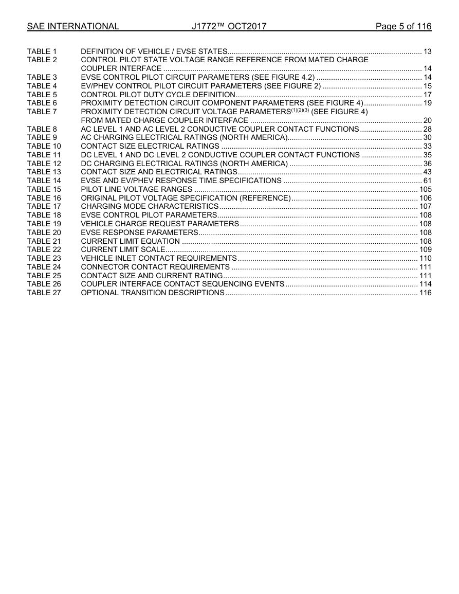
DEFINITION OF VEHICLE / EVSE STATES.............................................................................................. 13
CONTROL PILOT STATE VOLTAGE RANGE REFERENCE FROM MATED CHARGE
COUPLER INTERFACE ............................................................................................................................. 14
EVSE CONTROL PILOT CIRCUIT PARAMETERS (SEE FIGURE 4.2) ................................................... 14
EV/PHEV CONTROL PILOT CIRCUIT PARAMETERS (SEE FIGURE 2) ................................................ 15
CONTROL PILOT DUTY CYCLE DEFINITION .......................................................................................... 17
PROXIMITY DETECTION CIRCUIT COMPONENT PARAMETERS (SEE FIGURE 4) ............................ 19
PROXIMITY DETECTION CIRCUIT VOLTAGE PARAMETERS(1)(2)(3) (SEE FIGURE 4)
FROM MATED CHARGE COUPLER INTERFACE ................................................................................... 20
AC LEVEL 1 AND AC LEVEL 2 CONDUCTIVE COUPLER CONTACT FUNCTIONS .............................. 28
AC CHARGING ELECTRICAL RATINGS (NORTH AMERICA) ................................................................. 30
CONTACT SIZE ELECTRICAL RATINGS ................................................................................................. 33
DC LEVEL 1 AND DC LEVEL 2 CONDUCTIVE COUPLER CONTACT FUNCTIONS ............................. 35
DC CHARGING ELECTRICAL RATINGS (NORTH AMERICA) ................................................................ 36
CONTACT SIZE AND ELECTRICAL RATINGS ......................................................................................... 43
EVSE AND EV/PHEV RESPONSE TIME SPECIFICATIONS ................................................................... 61
PILOT LINE VOLTAGE RANGES ............................................................................................................ 105
ORIGINAL PILOT VOLTAGE SPECIFICATION (REFERENCE) ............................................................. 106
CHARGING MODE CHARACTERISTICS ................................................................................................ 107
EVSE CONTROL PILOT PARAMETERS ................................................................................................. 108
VEHICLE CHARGE REQUEST PARAMETERS ...................................................................................... 108
EVSE RESPONSE PARAMETERS .......................................................................................................... 108
CURRENT LIMIT EQUATION .................................................................................................................. 108
CURRENT LIMIT SCALE.......................................................................................................................... 109
VEHICLE INLET CONTACT REQUIREMENTS ....................................................................................... 110
CONNECTOR CONTACT REQUIREMENTS .......................................................................................... 111
CONTACT SIZE AND CURRENT RATING .............................................................................................. 111
COUPLER INTERFACE CONTACT SEQUENCING EVENTS ................................................................ 114
OPTIONAL TRANSITION DESCRIPTIONS ............................................................................................. 116
�
SAE INTERNATIONAL
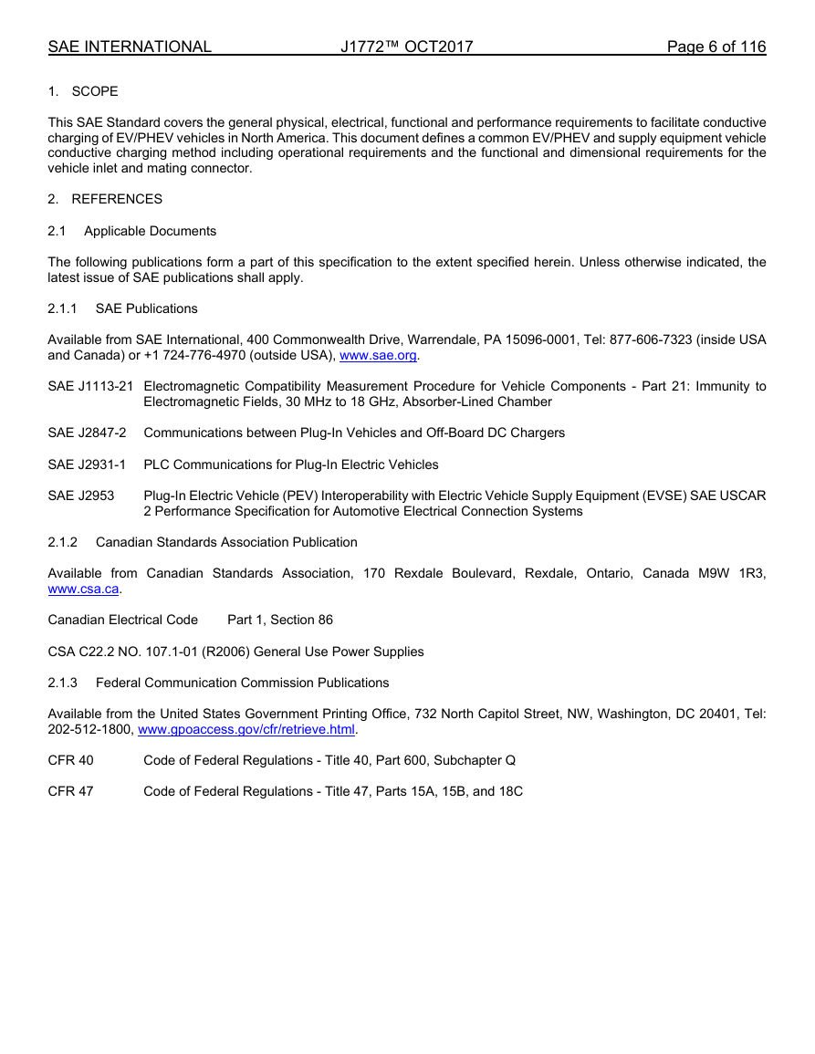
1. SCOPE
J1772™ OCT2017
Page 6 of 116
This SAE Standard covers the general physical, electrical, functional and performance requirements to facilitate conductive
charging of EV/PHEV vehicles in North America. This document defines a common EV/PHEV and supply equipment vehicle
conductive charging method including operational requirements and the functional and dimensional requirements for the
vehicle inlet and mating connector.
2. REFERENCES
2.1 Applicable Documents
The following publications form a part of this specification to the extent specified herein. Unless otherwise indicated, the
latest issue of SAE publications shall apply.
2.1.1 SAE Publications
Available from SAE International, 400 Commonwealth Drive, Warrendale, PA 15096-0001, Tel: 877-606-7323 (inside USA
and Canada) or +1 724-776-4970 (outside USA), www.sae.org.
SAE J1113-21 Electromagnetic Compatibility Measurement Procedure for Vehicle Components - Part 21: Immunity to
Electromagnetic Fields, 30 MHz to 18 GHz, Absorber-Lined Chamber
SAE J2847-2 Communications between Plug-In Vehicles and Off-Board DC Chargers
SAE J2931-1 PLC Communications for Plug-In Electric Vehicles
SAE J2953
Plug-In Electric Vehicle (PEV) Interoperability with Electric Vehicle Supply Equipment (EVSE) SAE USCAR
2 Performance Specification for Automotive Electrical Connection Systems
2.1.2 Canadian Standards Association Publication
Available from Canadian Standards Association, 170 Rexdale Boulevard, Rexdale, Ontario, Canada M9W 1R3,
www.csa.ca.
Canadian Electrical Code
Part 1, Section 86
CSA C22.2 NO. 107.1-01 (R2006) General Use Power Supplies
2.1.3 Federal Communication Commission Publications
Available from the United States Government Printing Office, 732 North Capitol Street, NW, Washington, DC 20401, Tel:
202-512-1800, www.gpoaccess.gov/cfr/retrieve.html.
CFR 40
CFR 47
Code of Federal Regulations - Title 40, Part 600, Subchapter Q
Code of Federal Regulations - Title 47, Parts 15A, 15B, and 18C
�
SAE INTERNATIONAL
2.1.4
International Electrotechnical Commission Publication
J1772™ OCT2017
Page 7 of 116
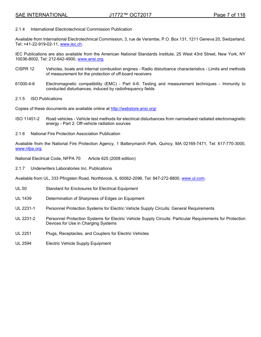
Available from International Electrotechnical Commission, 3, rue de Verambe, P.O. Box 131, 1211 Geneva 20, Switzerland,
Tel: +41-22-919-02-11, www.iec.ch.
IEC Publications are also available from the American National Standards Institute, 25 West 43rd Street, New York, NY
10036-8002, Tel: 212-642-4900, www.ansi.org.
CISPR 12
61000-4-6
Vehicles, boats and internal combustion engines - Radio disturbance characteristics - Limits and methods
of measurement for the protection of off-board receivers
Electromagnetic compatibility (EMC) - Part 4-6: Testing and measurement techniques - Immunity to
conducted disturbances, induced by radiofrequency fields
2.1.5
ISO Publications
Copies of these documents are available online at http://webstore.ansi.org/
ISO 11451-2 Road vehicles - Vehicle test methods for electrical disturbances from narrowband radiated electromagnetic
energy - Part 2: Off-vehicle radiation sources
2.1.6 National Fire Protection Association Publication
Available from the National Fire Protection Agency, 1 Batterymarch Park, Quincy, MA 02169-7471, Tel: 617-770-3000,
www.nfpa.org.
National Electrical Code, NFPA 70
Article 625 (2008 edition)
2.1.7 Underwriters Laboratories Inc. Publications
Available from UL, 333 Pfingsten Road, Northbrook, IL 60062-2096, Tel: 847-272-8800, www.ul.com.
UL 50
Standard for Enclosures for Electrical Equipment
UL 1439
Determination of Sharpness of Edges on Equipment
UL 2231-1
Personnel Protection Systems for Electric Vehicle Supply Circuits: General Requirements
UL 2231-2
Personnel Protection Systems for Electric Vehicle Supply Circuits: Particular Requirements for Protection
Devices for Use in Charging Systems
UL 2251
UL 2594
Plugs, Receptacles, and Couplers for Electric Vehicles
Electric Vehicle Supply Equipment
�
SAE INTERNATIONAL
2.2 Related Publications
J1772™ OCT2017
Page 8 of 116
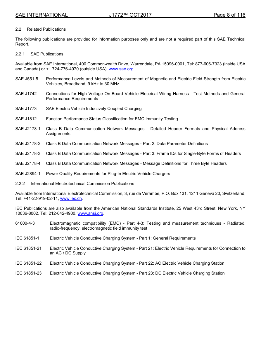
The following publications are provided for information purposes only and are not a required part of this SAE Technical
Report.
2.2.1 SAE Publications
Available from SAE International, 400 Commonwealth Drive, Warrendale, PA 15096-0001, Tel: 877-606-7323 (inside USA
and Canada) or +1 724-776-4970 (outside USA), www.sae.org.
SAE J551-5
Performance Levels and Methods of Measurement of Magnetic and Electric Field Strength from Electric
Vehicles, Broadband, 9 kHz to 30 MHz
SAE J1742
Connections for High Voltage On-Board Vehicle Electrical Wiring Harness - Test Methods and General
Performance Requirements
SAE J1773
SAE Electric Vehicle Inductively Coupled Charging
SAE J1812
Function Performance Status Classification for EMC Immunity Testing
SAE J2178-1 Class B Data Communication Network Messages - Detailed Header Formats and Physical Address
Assignments
SAE J2178-2 Class B Data Communication Network Messages - Part 2: Data Parameter Definitions
SAE J2178-3 Class B Data Communication Network Messages - Part 3: Frame IDs for Single-Byte Forms of Headers
SAE J2178-4 Class B Data Communication Network Messages - Message Definitions for Three Byte Headers
SAE J2894-1 Power Quality Requirements for Plug-In Electric Vehicle Chargers
2.2.2
International Electrotechnical Commission Publications
Available from International Electrotechnical Commission, 3, rue de Verambe, P.O. Box 131, 1211 Geneva 20, Switzerland,
Tel: +41-22-919-02-11, www.iec.ch.
IEC Publications are also available from the American National Standards Institute, 25 West 43rd Street, New York, NY
10036-8002, Tel: 212-642-4900, www.ansi.org.
61000-4-3
Electromagnetic compatibility (EMC) - Part 4-3: Testing and measurement techniques - Radiated,
radio-frequency, electromagnetic field immunity test
IEC 61851-1
Electric Vehicle Conductive Charging System - Part 1: General Requirements
IEC 61851-21
Electric Vehicle Conductive Charging System - Part 21: Electric Vehicle Requirements for Connection to
an AC / DC Supply
IEC 61851-22
Electric Vehicle Conductive Charging System - Part 22: AC Electric Vehicle Charging Station
IEC 61851-23
Electric Vehicle Conductive Charging System - Part 23: DC Electric Vehicle Charging Station
�


 2023年江西萍乡中考道德与法治真题及答案.doc
 2012年重庆南川中考生物真题及答案.doc
 2013年江西师范大学地理学综合及文艺理论基础考研真题.doc
 2020年四川甘孜小升初语文真题及答案I卷.doc
 2020年注册岩土工程师专业基础考试真题及答案.doc
 2023-2024学年福建省厦门市九年级上学期数学月考试题及答案.doc
 2021-2022学年辽宁省沈阳市大东区九年级上学期语文期末试题及答案.doc
 2022-2023学年北京东城区初三第一学期物理期末试卷及答案.doc
 2018上半年江西教师资格初中地理学科知识与教学能力真题及答案.doc
 2012年河北国家公务员申论考试真题及答案-省级.doc
 2020-2021学年江苏省扬州市江都区邵樊片九年级上学期数学第一次质量检测试题及答案.doc
 2022下半年黑龙江教师资格证中学综合素质真题及答案.doc