IEEE TRANSACTIONS ON COMMUNICATIONS, VOL. COM-34, NO. 5 , MAY 1986
423
A BPSK/QPSK Timing-Error Detector for Sampled
Receivers
Abstract-A
simple algorithm for detection of timing error of a
synchronous, band-limited, BPSK or QPSK data stream is proposed. The
algorithm requires only two samples per symbol for its operation. One of
the two samples is also used for the symbol decision. Derivation of the s-
curve reveals a sinusoidal shape.
for digital data
S , AMPLED implementations of receivers
I. INTRODUCTION
signals are growing more popular as components-notably
digital signal processors-improve
in capability. There is a
need for sampled algorithms to replace the continuous-time
methods that have predominated heretofore.
This paper introduces an algorithm for timing error detec-
tion in a receiving modem. Algorithm operations are simple
and only two samples of the signal are required for each data
symbol. Moreover, one of the two samples also serves for the
symbol strobe (i.e., the sample on which the symbol decision
is made).
The algorithm is intended for synchronous, binary, base-
band signals and for BPSK or QPSK (balanced, nonstaggered)
passband signals, with approximately 40-100 percent excess
bandwidth.
Other sampled timing algorithms have
.been presented
earlier. Mueller and Muller [l] wrote a classic explanation of
timing recovery based on just one sample per symbol and
requiring decision-directed operations. Note that correct deci-
sions in .a carrier system depend upon prior acquisition of
carrier phase.
not
By contrast, the algorithm introduced in this paper is
decision directed. Furthermore, clock recovery is quite
independent of carrier .phase.
Other papers [2]-[5] have foliowed the lead of [l]. A
wave difference method
different scheme, dubbed the
(WDM), was proposed in [6]. In essence, the WDM finds the
average location of zero-slope of the received, filtered signal
pulses. Numerous samples per symbol appear to tie required
for the original method of [6].
Reference [7] extends the WDM, shows how to reduce it to
two samples per symbol, suggests implementation details, and
provides analyses of performance. Neither of the two sample
points in [7] coincides with the decision strobe point. Either
four samples per symbol must be taken or else (as in [7]) the
two samples per symbol must be interpolated to an effective
four samples per symbol. (Interpolation in [7] is accomplished
with a digital .delay of a quarter-symbol interval.) Both [6] and
[7] treat clock recovery only for baseband signals.
The method introduced in this paper, .although developed
independently, has resemblances to the WDM of [7]. Its major
points of difference are: only two samples per symbol are
employed, without explicit interpolation; one sample coincides
with the decision instant; and
well as baseband signals,.
carrier signals are handled as
References [I] and [7] contain informative summaries
of
analog clock-recovery methods, with references.
This paper is organized as follows. A model of a receiving
modem is shown in Section I1 add some characteristics of the
new algorithm are stated in Section 111. A baseband version of
the algorithm is developed in Section IV: Derivation of the S-
curi.e (sinusoidal for a band-limited signal) is relegated to
that the al-
Appendix A, while Appendix B demonstrates
gorithm is independent of carrier phase.
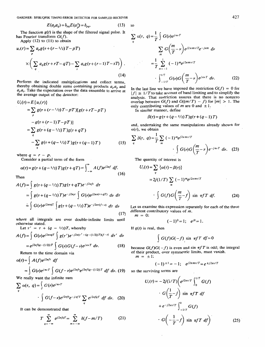
11. RECEIVER MODEL
passband signal is .demodulated
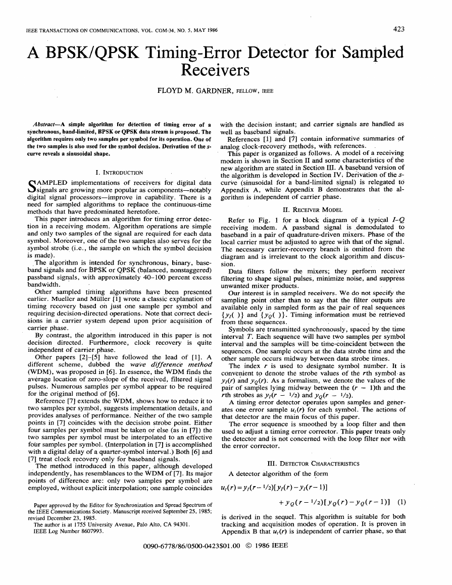
Refer to Fig. 1 for a block diagram
of a typical I-Q
receiving modem. A
to
baseband in a pair of quadrature-driven mixers. Phase of the
local carrier must be adjusted to agree with that of the signal.
The necessary carrier-recovery branch is
omitted from the
diagram and is irrelevant to the clock algorithm and discus-
sion.
Data filters follow the mixers;
they perform receiver
filtering to shape signal pulses, minimize noise, and suppress
unwanted mixer products.
Our interest is in sampled receivers. We do not specify the
sampling point other
than to say that the filter outputs are
available only in sampled form as the pair of real sequences
{y,( ) } and {ye( ) } . Timing information must be retrieved
from these sequences.
Symbols are transmitted synchronously, spaced by the time
interval T. Each sequence will have t*o samples per symbol
interval and the samples will be time-coincident between +e
sequences. One sample occurs at the data strobe time and the
other sample occurs midway between data strobe times.
The index r is used to designate symbol number. It is
convenient to denote the strobe values of the rth symbol- as
yl(r) and ye('): As a formalism, we denote the values of the
pair of samples lying midway between the (r - 1)th and the
rth strobes as yl(r - 1/2) and yQ(r - V2).
A timing error detector operates upon samples and gener-
ates one error sample ut@) for each symbol. The actions of
that detector are the main focus of this paper.
The error sequence is smoothed by a loop filter and then
used to adjust a timing error corrector. This paper treats only
the detector and is not concerned with the loop filter nor with
the error corrector.
111. DETECTOR CHARACTERISTICS
Paper approved by the Editor for Synchronization and Spread Spectrum of
the IEEE Communications Society. Manuscript received September 25, 1985;
revised December 23, 1985.
The author is at 1755 University Avenue, Palo Alto, CA 94301.
IEEE Log Number 8607993.
is suitable for both
is derived in the sequel. This algorithm
tracking and acquisition modes of operation. It is proven in
Appendix B that ut@) is independent of carrier phase, so that
0090-6778/86/0500-0423$01 .OO 0 1986 XEEE
�
424
IiQ Demodulator
I
I
I
To Decision
Process
4:;:;a
{YQ( ) I
Filter
Timing
Error
Corrector
Error
(ut(r)} Det ct
IEEE TRANSACTIONS ON COMMUNICATIONS, VOL. COM-34. NO. 5 , MAY 1986
,That eliminates the effects
instead of the actual values.
of
much noise. If all data filtering has been performed prior to the
strobe point, then the sign of the strobe value is ,he optimum
hard decision on the symbol and the algorithm effectively
becomes decision directed. This expedient is
known to
improve tracking
capability. (But acquisition performance
may suffer in a decision-directed operation.) Note that use of
the strobe signs, instead of actual values, eliminates the need
for actual multiplications in the
attractive
feature for digital processors.
algorithm-an
The decision-directed version of the algorithm will be
recognized as very similar to the digital transition tracking
loop of Lindsey and Simon [8].
We can see a source of self noise in either version of &is
algorithm. If the excess bandwidth is less than 100 percent, the
zero crossings of data transitions
do not all lie midway
between the strobe points. There is a scatter of crossing points,
centered on the midway point. The average location is correct,
but any individual trajectory can depai-t from the average,
causing self noise.
in this section:
One last comment is appropriate
The
algorithm takes its information from three different sample
points in order to produce one timing-error point. There is a
delay in computing the error
adjusted within the three-point span of the algorithm, so the
timing error at the last point in the span does not necessarily
remain the same as the error at the first point. Equivalently,
the algorithm contains memory. These features must be taken
into account in the analysis of the tracking loop.
Iv. DEdrVATiON OF ALGORITHM
sample. The timing can be
-This section develops the timing detector
by physical
reasoning from data waveforms. Past experience with timing
recovery in analog systems is used as a guide for the all-digital
detector.
Waveform Approach
We start out
with the problem
of recovering timing
information from a baseband data stream. To that end; we
postulate the existence of an equivalent analog, baseband
signal underlying the digital sequence that actually occurs in
the processor.
on the
continuous signal
than on the discrete sequence. Any zero-
memory operations performed on the continuous signal will
commute with sampling, so that equivalent results are obtained
by performing the same operations on the discrete sequence.
to visualize operations
It is easier
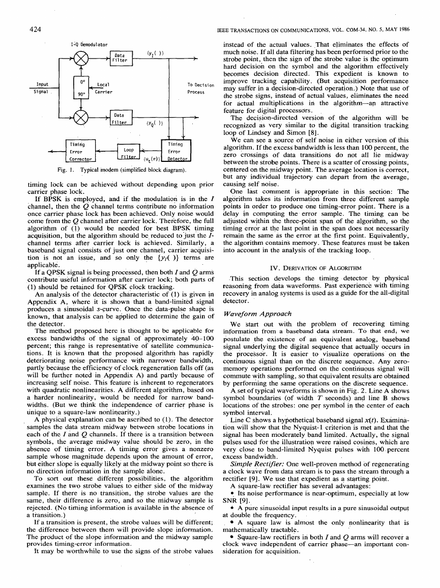
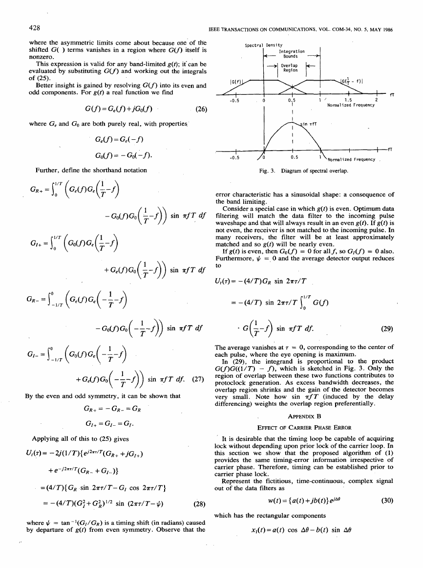
A, set of typical waveforms is shown in Fig. 2 . Line A shows
symbol boundaries (of width T seconas) and line B shows
locations of the strobes: one per symbol in the center of each
symbol interval.
Line C shows a hypothetical baseband signal x(t). Examina-
tion will show that the Nyquist-1 criterion is met and that the
signal has been moderately band limited. Actually, the signal
pulses used for the illustration were raised cosines, which are
very close
to band-limited Nyquist pulses With 100 percent
excess bandwidth.
Simple Rectifier: One well-proven method of regenerating
a clock wave from data stream is to pass the stream through a
rectifier [9]. We use that expedient as a starting point.
A square-law rectifier has several advantages:
0 Its noise performance is near-optimum, especially at low
SNR [9].
at double the frequency.
mathematically tractable.
4 A pure sinusoidal input results in a pure sinusoidal output
A square law
is almost the only nonlinearity that is
Square-law rectifiers in both I and Q arms will recover a
important con-
clock wave independent of carrier phase-an
sideration for acquisition.
Fig. 1. Typical modem (simplified block diagram).
timing lock can be achieved
carrier phase lock.
without depending upon prior
If BPSK is employed, and if the modulation is in the I
channel, then the Q channel terms contribute no information
once carrier phase lock has been achieved. Only noise would
come from the Q channel after carrier lock. Therefore, the full
algorithm of (1) would be needed for best -BPSK timing
acquisition, but the algorithm should be, reduced to just the I-
channel terms after carrier
baseband signal consists of just one channel, cartier acquisi-
tion, is not an issue, and so only the {yl( )} terms are
applicable.
lock is achieved. Similarly, a
If a QPSK signal is being processed,
then both I and Q arms
contribute useful information after carrier lock; both parts of
(1) should be retained for QPSK clock tracking.
An analysis of the detector characteristic of (1) is given in
band-limited signal
it is shown that a
Appendix A, where
produces a sinusoidal
s-curve. Once the data-pulse shape is
known, that analysis can be applied to determine the gain of
the detector.
The method proposed here is thought to be applicable for
of the signal of approximately 40-100
excess bandwidths
percent; this range is representative
of satellite communica-
tions. It is known that
the proposed algorithm has rapidly
deteriorating qoise performance
with narrower bandwidth,
partly because the efficiency of clock regeneration falls off (as
will be further noted in Appendix A) and partly because of
increasing self noise. This feature is inherent
to regenerators
with quadratic nonlinearities. A different algorithm, based on
a harder nonlinearity,
widths. (But we think the independence of carrier phase is
unique to a square-law nonlinearity.)
would be needed for narrow band-
A physical explanation can be ascribed to (1). The detector
samples the data stream midway between strobe locations in
each of the I and Q channels. If there is a transition between
symbols, the average midway value should be zero, in the
absence of timing error. A timing
sample whose magnitude depends upon the amount of error,
but either slope is equally likely at the midway point so there is
no direction information in the sample alone.
error gives a nonzero
To sort out these differevt possibilities, the algorithm
examines the two strobe values to either side of the midway
sample. If there is no transition, the strobe values are the
same, their difference is zero, and so the midway sample is
rejected. (No timing information is available in the absence of
a transition.)
If a transition is present, the strobe values will be different;
the difference between them will provide slope information.
The product of the slope information and the midway sample
provides timing-error information.
It may be worthwhile to use the signs of the strobe values
�
GARDNER: BPSK/QPSK TIMING-ERROR DETECTOR FOR SAMPLED RECEIVER
Borders , I , I , I
A
symbol
I
C
I
I ~ ~ I
-
l + C J l + + + + 4 + +
I
I
I
I
I
I
I
1
425
Fig. 2. Timing waveforms.
We will start the derivation with a square-law rectifier.
Line D of Fig. 2 shows the data stream after square-law
rectification. Evident in the picture are a dc component (an
inevitable output from a rectifier) plus a double-frequency
component at the symbol rate. This protoclock component is
equivalent to a pure sinewave
interrupted by gaps when there are no transitions in the data.
An analog clock-recovery scheme would employ a narrow-
band filter or a phase-lock loop to extract the desired clock line
and reject the various disturbances.
at the symbol frequency,
The same approach is feasible in a digital system, but is not
very convenient. Proper operation with a filter or PLL scheme
would necessitate good reconstruction of the protoclock and
that cannot be done with just two samples per symbol. (Two
samples per cycle of a sinewave
limit of the
sampling theorem; the protoclock has a bandwidth wider than
1 / T and cannot be reconstructed from samples at a rate
2/T.)
is the upper
of
Our objective i s not to reconstruct the protoclock, but
to
does not inherently require
determine timing error-which
protoclock reconstruction.
Examining line D, it can be seen that samples taken at
locations of k 1/4T away from the strobe point fall at equal-
amplitude, but opposite-slope points on the useful portions of
the protoclock. When timing is correct, the difference between
those two samples-labeled E for early and L for late-will be
zero (in those locations where a data transition exists). If the
signal is delayed with respect to the sampling, then the value of
one sample increases and the other decreases. The difference
between sartiple,values is a measure of timing error.
To formalize the method, assign an index r to each timing
in the rth symbol
sample, so that the two timing samples
interval. are denoted E(r) and L(r). This introductory al-
gorithm would be
ut(r)=E(r)-L(r-l)
= x 2 ( ~ + ( r - 1 1 / 4 ) T ) - x 2 ( ~ + ( r - 5 / 4 ) T )
(2)
whereas the rth strobe is taken at t = rT + r , and 7 is the
timing shift from desired delay.
for the
in the example, that u,( ) will be
in the absence of additive noise, and
idealized waveforms used
zero when transitions are missing. That festure avoids
significant self noise.
Note that
A slightly different algorithm,
E(r) - L(r), could have
been employed instead. It would also provide a measure of the
timing error and a successful loop could
be based upon it.
However, a large error sample is generated by this algorithm
for many locations where there are no transitions. It is true that
an opposite-sign error-sample is certain to be generated later
and that the two large samples cancel out
in the long-term
tracking. However, in the short term, the large error samples
contribute to self noise. For that reason, the selected algorithm
is superior to the alternative. The same choice, with the same
self-noise consequences, will reappear in subsequent develop-
ments. Without further comment, we
pair giving the best rejection of self noise.
will select the sample
The algorithm of ( 2 ) . is workable. From experience with
continuous systems
performance could be attained
links. However, it has two deficiencies that should be
remedied.
[lo] we can anticipate that satisfactory
in typical communications
Although it needs only two samples per symbol, neither
Therefore,, the
of those samples is the data-strobe sample.
postfilter operations require at least three samples per symbol,
thereby placing a greater computing burden on the data filters.
0 . No self noise arises with the idealized waveforms of the
illustration. But that happy condition occurs only because the
illustrative waveforms are time-limited. When band-limited,
time-extended waveforms are used, then self noise will arise to
some extent.
Let us attack the self noise first.
It is well established [l 13 that a suitable prefilter in front of
the rectifier, plus suitable postfiltering, can suppress self noise
completely. That is the next approach examined.
�
426
Prefilter Method: Line E shows the output x,(t) of a
prefilter which has x(t), from line C, as its input. For time-
limited pulses [12], x,(t) is simply the derivative of x(t). For
band-limited pulses, the spectrum ofx,(t) is band limited and
symmetric about the Nyquist frequency 1 /2 T (See [ 1 11 ) .
A protoclock is generated by rectifying x,(t), as illustrated
in line F. For the particular, idealized waveforms used in Fig.
2, it turns out that Line F is simply the inversion and level shift
of line D. The same arguments on sampling and the same
timing algorithm are appropriate.
In the absence of a postfilter,
it is not apparent that the
prefilter affords self-noise relief for band-limited waveforms.
A more detailed analysis would be needed to demonstrate that
feature. Instead, we merely note that the idealized prefilter'for
the idealized illustrative waveform has not relieved the shift of
the timing samples from the strobe location.
A differentiator,
for time-limited pulses, or an optimum
likely to be rather
prefilter, for band-limited pulses, it is
complicated and would add unduly to the computation burden.
It has been shown
[13] that fairly c k d e approximations to
ideal prefilters provide substantial improvement of self noise.
Therefore, we
of
simplicity and restrict the method to very simple prefilters.
, Delay Differencing: Let the prefilter or differentiator be
approximated by the operation
compromise optimality in the interest
x d ( t ) = x ( t ) - x ( t - t d )
(3)
where td is a suitably chosen delay time. In paiticular, if td =
T/2, then the average delay of xd is T/4-which
is the time
shift between the strobe point and the timing samples that has
arisen in the two previous approaches.
Line G shows the result if the signal of line C is delay-
differenced with a delay of td = T/2. 'Comparison with line E
shows similar, but not identical waveforms.
The delay-differenced waveform is
passed through a
square-law rectifier, yielding
form. Once again, the
information can be retrieved by the algorithm
line H, for the example wave-
protocloc,k appears and timing-error
u f ( r ) = E ( r ) - L ( r - 1).
(4)
However, now observe that E(r) coincides with the strobe
time for the rth symbol; the delay in the differencing network
shifted the time for the timing samples and eliminated *e need
for a third sample. One timing sample now coincides with the
data strobe and the other falls midway between data strobes.
(The strobe locations are carried on eacp waveform abscissa as
vertical tick marks in Fig. 2 . )
In this roundabout manner we have devised a timing-error
detector algorithm that requires only two samples per symbol
(one sample coincident with
the data strobe), that has some
self-noise rejection properties, and that can be performed with
minimal computing burden (one subtraction and one squaring
per symbol interval). Now let us ,see what improvements are
possible.
Formai Reductions
algorithm 'expression and discover
In this section we perform formal algebraic manipulations
that there are
no useful
self noise,
on the
elements hidden in
output. Since their presence could only generate
they are eliminated &nd a stripped algorithm is derived instead.
the algorithm that contribute
S t g t with
xd(t)=x(t)-x(t- T/2)
x$(t)=x2(t)+x2(t- T / 2 ) - 2 x ( t ) x ( t - T/2).
( 5 )
(6)
IEEE TRANSACTIONS
ON
COMMUNICATIONS, VOL.' COM-34, NO. 5 , MAY 1986
Upon sampling at t = rT + r and rT + r - T/2, we obtain
E(r) =x2,(rT+ 7)
= x2(7 + rT) + x2(r + ( r - 1/2) T )
-2X(7+FT)X(T+(r-'1/2)T)
~ ( r - 1 ) = ~ 2 ( r + ( r - - / 2 ) T ) + x ~ ( r + ( r - l ) T )
- 2 x ( r + ( r - 1 / 2 ) T ) x ( r + ( r - l ) T ) . -(7)
Let the algorithm be
u f ( r ) = L ( r - 1 ) - E ( r ) .
(8)
of sign has no significance in the formal
The reversal
manipulations or in the processor's computation burden, but
assures negative slope at the tracking point of the detector
output. See Appendix A.
Both elements of (8) contain a term x2(7 + (r - 1/2)T);
the subtraction cancels those terms. Collecting terms after the
cancellation, the algorithm is composed of the elements
u,(r)=x2(7+(r- l)T)-x2(r+rT)
+ 2 x ( r + ( r - 1 1 / 2 ) ~ ) { x ( r + r ~ ) - x ( T + ( r - l ) ~ ) } .
Useful output of the algorithm is the
(9)
average over many
samples, not the value of an isolated sample. Denote Uf(r) =
Avg, ut(r) as the average over many samples, so that
Vf(7) = Avg { x2(r + ( r - 1) T } - Avg { x2(7 + rT)}
+ 2 Avg { ~ ( 7 + ( r - ~ / 2 ) T ) ( x ( 7 + r T ) - ~ ( 7 + ( r - l ) T ) ) } .
(10)
The first two terms must be equal; the ensemble
average
cannot depend upon the index r because the underlying signal
is cyclostationary. Therefore, those averages must cancel. The
presence of the x*( ) terms does not contribute to the useful
average output; we must suspect them as potential sources of
self ,noise.' Therefore,' let us eliminate them.
The remaining terms' are of the form
U , ( r ) = X ( 7 + ( T - 1 / 2 ) T ) { X ( 7 + r T ) - X ( 7 + ( r - 1 ) T ) }
= x ( r - l h ) { x ( r ) - x ( r - l)}.
(1 1)
This is
the proposed timing-detector algorithm for real,
baseband signals.'Two such computations, one each from the I
and from the Q channel, are added when processing a
demodulated carrier signal. The sum'is the'algorithm of (1).
APPENDIX A
DERIVATION OF S-CURVE
Satisfactory design of. the timing loop requires that the
detector characteristic-average
error
7-be known. That is derived 'for the baseband algorithm of
(1 1) in this Appendix. A phase-independent extension
to the Z-
Q algorithm of (1) is demonstrated in Appendix B.
output versus timing
Let the underlying, time-continuous signal be a
PAM
stream with the format
x ( t ) = C @ p g ( t - P T )
(12)
where this summation, and those
doubly infinite.
to follow, is assumed to be
The sequence {ap} is taken from a binary library where a,
= k 1 . We will assume that the ap have zero mean and are
uncorrelated. That is,
- E(ap)=O
�
GARDNER: BPSKIQPSK TIMING-ERROR DETECTOR FOR SAMPLED RECEIVER
(13)
The function g(t) is the shape of the filtered signal pulse. It
E(apaq) = 6,,E(a3 = aPq.
Apply (12) to (1
has Fourier transform G( f ) .
to obtain
ut(r) = x apg(r+ ( r - Vz) T - p T )
1)
so
a
P
=' j G(v)ejruT
a(r, 4)
T
427
(14)
indicated multiplications and collect terms,
Perform the
thereby obtaining double sums containing products aPaq and
spas. Take the expectation over the data ensemble to arrive at
the average output of the detector:
U,(d=E{Ut(r))
P
- g ( r + ( r - 1 ) T - p T ) ]
= x g(r+ ( r - ' / z ) T - p T ) [ g ( r + r T - p T )
=e g ( r + ( q - l / z ) T ) g ( r + q T )
4 -e g ( r + ( q - W T ) g ( 7 + ( q - 1 ) T )
4
where q = r - p .
m
Then
Consider a partial term of the form
( ~ ( ~ ) = g ( 7 + ( q - - / z ) p ) g ( ~ + q T ) =
A ( f ) = 1 g(r+(q-1/z)T)g(7+qT)e-jZ*fr dr
1 A(f)ejZuf df.
= 1 g ( r + ( q - 1/z)k)e-jZrfl s G(v)ejZru(r+qT) dv dr
1 G(v)ejZTuQT
s g ( r + ( q - 1/2)T)e-jzur(f-u) dr dv
- m
(16)
where all integrals are over
otherwise stated.
Let 7' = 7 + (q - %)T, whereby
double-infinite limits
(17) m = 0:
until
If g ( t ) is
real,
then
In the last line we have imposed the restriction G ( f ) = 0 for
If1 2 1/T to take account of band limiting and to simplify the
no nonzero
analysis. That restriction assures
overlap between G ( f ) and G ( ( m / T ) - f) for Iml > 1. The
only contributing values of m are 0 and & 1.
that there is
In similar manner, define
P(7) = g(7 + (4 - 1/21 T)g(r+ (q - 1 ) T)
and, undertaking the same manipulations already shown for
(Y(T), we obtain
( 1 5 )
m
l G(v)G(;-v)e-jrvT dv.
*
(23)
The quantity of interest is
i 4 7 ) - P(7))
Ut(7) =
4
= 2 j ( l / T )
m
(- l)mejzrmr/T
s C ( f ) G ( T - f ) sin nfT df. (24)
*
Let us examine this expression separately for each of the three
different contributory values of m.
It can be demonstrated that
4
m
m
q = - m
m = --m
io G ( f )
- l / T
+ e-jZrr/T
* G ( -$-f)
sin nfT df)
�
428
TRANSACTIONS
IEEE
COMMUNICATIONS,
ON
VOL. COM-34,
NO.
5, MAY 1986
where the asymmetric limits come about because
one' of the
shifted G( ) terms vanishes in a region where G ( f ) itself is
nonzero.
This expression is valid for any band-limited g(t); it' can be
evaluated by substituting G ( f ) and working out the integrals
of (25).
Better insight is gained by resolving G ( f ) into its even and
odd components. For g(t) a real function we find
G ( f 1 = Ge ( f ) +jGo(f)
where G, and Go are both purely real, with properties
G A f ) = Ge( -f)
Go(f) = - Go( - f
Further, define the shorthand notation
+Ge(f)Go -- f
sin nf T df
(k ))
+Ge(f)Go( -;- f ) ) sin rf T df.
(27)
By the even and odd symmetry, it can be shown that
GR+ = - GR- = GR
GI+ = GI- = GI.
Applying all of this to (25) gives
Ut(r)= -2j(l/T){e'2TT/T (GR+ + ~ G I + )
+ e - j 2 a ~ / T (GR- + GI-)}
= (4/T){ GR .sin .2nr/T- GI cos 2nr/T}
= - (41 T)( G: + G i ) l l 2 sin (2~7-/ T - $)
(28)
I
0
0
-0.5
I I
-0.5
1 '
2
Normalized Frequency
1.5
0.5
I
I
I
I
0.5
"Normalized
I
Frequency
I f f
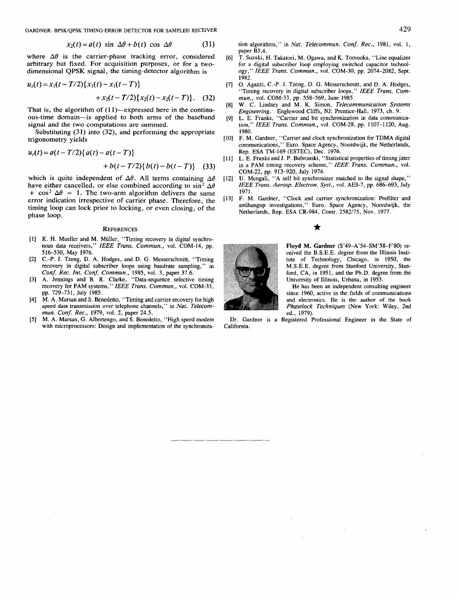
Fig. 3. Diagram of spectral overlap.
error characteristic has a sinusoidal shape: a consequence of
the band limiting.
Consider a special case in which g(t) is even. Optimum data
filtering will match the data filter to the incoming pulse
waveshape and that will always result in an even g(t). If g(t) is
not even, the receiver is not matched to the incoming pulse. In
many receivers, the filter
matched and so g(t) will be nearly even.
will be at least approximately
If g(t) is even, then Go(f) = 0 for allf, so G I ( f ) = 0 also.
Furthermore, $ =, 0 and the average detector output reduces
to
Ut(r) = - ( ~ / T ) G R sin 2 m / T
= - ( 4 / T ) sin 2 m / T j G ( f )
1/T
0
In (29), the integrand
The average vanishes at r = 0, corresponding to the center of
each pulse, where the eye opening is maximum.
G ( f ) G ( ( l / T ) - f), which is sketched in Fig. 3. Only the
region of overlap between these two functions contributes to
protoclock generation. As excess bandwidth decreases, the
overlap region shrinks and the gain of the detector becomes
very small. Note
differencing) weights the overlap region preferentially.
how sin ?rf T (induced by the delay
is proportional to the product
APPENDIX B
EFFECT OF CARRIER PHASE ERROR
' It is desirable that the timing loop be capable of acquiring
lock without depending upon prior lock of the carrier loop. In
of (1)
this section we show that the proposed algorithm
provides the same timing-error information irrespective
of
carrier phase. Therefore, timing can be established prior to
carrier phase lock.
Represent the fictitious, time-continuous, complex signal
out of the data filters as
w ( t ) = {a(t)+jb(t)}ejA8
(30)
where $ = tan-I(GI/GR) is a timing shift (in radians) caused
by departure of g(t) from even symmetry. Observe that the
which has the rectangular components
x l ( t ) = a ( t ) cos Ae-b(t) sin A0
�
x2(t) = a(t) sin A8 + b(t) cos A8
GARDNER: BPSKIQPSK TIMING-ERROR DETECTOR FOR SAMPLED RECEIVER
(31)
where A0 is the carrier-phase
tracking error, considered
arbitrary but fixed. For acquisition purposes, or for a two-
dimensional QPSK signal, the timing-detector algorithm is
ut(t)=xl(t- T/2){x1(t)-x,(t- T ) }
+ ~ 2 ( t - T / 2 ) { ~ 2 ( t ) - x z ( t - T ) } . (32)
That is, the algorithm of (1 1)-expressed here in the continu-
ous-time domain-is applied to both arms of the baseband
signal and the two computations are summed.
Substituting (31) into (32), and performing the appropriate
trigonometry yields
ul(t)=a(t- T/2){a(t)-a(t- T ) }
+b(t- T / 2 ) { b ( t ) - b ( t - T ) } (33)
which is quite independent of AO. All terms containing A0
have either cancelled, or else combined according to sin2 A0
+ cos2 A0 = 1. The two-arm algorithm delivers
the same
error indication irrespective of carrier phase. Therefore, the
timing loop can lock prior to locking, or even closing, of the
phase loop.
REFERENCES
K. H. Mueller and M. Muller, “Timing recovery in digital synchro-
receivers,” IEEE Trans. Commun., vol. .COM-14, pp.
nous data
516-530, May 1976.
C.-P. J. Tzeng, D. A. Hodges, and D. G. Messerschmitt, “Timing
recovery in digital subscriber loops using baudrate
sampling,” in
Conf. Rec. Int. Conf. Cornmun., 1985, vol. 3, paper 37.6.
A. Jennings and B.
recovery for PAM systems,” IEEE Trans. Commun., vol. COM-33,
pp. 729-731, July 1985.
M. A. Marsan and S . Benedetto, “Timing and carrier recovery for high
speed data transmission over telephone channels,” in Nat. Telecom-
mun. Conf. Rec., 1979, vol. 2, paper 24.5.
M. A. Marsan, G. Albertengo, and S. Benedetto, “High speed modem
with microprocessors: Design and implementation of the synchroniza-
R. Clarke, “Data-sequence selective timing
429
tion algorithms,” in Nut. Telecommun. Conf. Rec., 1981, vol. 1,
paper B3.4.
T. Suzuki, H. Takatori, M. Ogawa, and K. Tomooka, “Line equalizer
for a digital subscriber loop employing switched capacitor technol-
ogy,” IEEE Trans. Cornmun., vol. COM-30, pp. 2074-2082, Sept.
1982.
0. Agazzi, C.-P. J. Tzeng, D. G. Messerschmitt, and D. A. Hodges,
“Timing recovery in digital subscriber loops,” IEEE Trans. Com-
mun., vol. COM-33, pp. 558-569, June 1985.
W. C. Lindsey and M. K. Simon, Telecommunication Systems
Engineering. Englewood Cliffs, NJ: Prentice-Hall, 1973, ch. 9.
L. E. Franks, “Carrier and bit synchronization in data communica-
tion,” IEEE Trans. Commun., vol. COM-28, pp. 1107-1120, Aug.
1980.
F. M. Gardner, “Carrier and clock synchronization for TDMA digital
communications,” Euro. Space Agency, Noordwijk, the Netherlands,
Rep. ESA TM-169
L. E. Franks and J. P. Bubrouski, “Statistical properties of timing jitter
in a PAM timing recovery scheme,” IEEE Trans. Cornmun., vol.
COM-22, pp. 913-920, July 1974.
U. Mengali, “A self bit synchronizer matched to the signal shape,”
IEEE Trans. Aerosp. Electron. Syst., vol. AES-7, pp. 686-693, July
1971.
F. M. Gardner, “Clock and carrier synchronization: Prefilter and
antihangup investigations,” Euro. Space Agency, Noordwijk, the
Netherlands, Rep. ESA CR-984, Contr. 2582/75, Nov. 1977.
(ESTEC), Dec. 1976.
*
Floyd M. Gardner (S’49-A’54-SM’58-F’80) re-
ceived the B.S.E.E. degree from the Illinois Insti-
tute of Technology, Chicago, in 1950, the
M.S.E.E. degree from Stanford University, Stan-
ford, CA, in 1951, and the Ph.D. degree from the
University of Illinois, Urbana, in 1953.
He has been an independent consulting engineer
since 1960, active in the fields of communications
and electronics. He is the author of the book
Phaselock Techniques (New York: Wiley, 2nd
ed., 1979).
Dr. Gardner is a Registered Professional Engineer in the State of
California.
�


 2023年江西萍乡中考道德与法治真题及答案.doc
 2012年重庆南川中考生物真题及答案.doc
 2013年江西师范大学地理学综合及文艺理论基础考研真题.doc
 2020年四川甘孜小升初语文真题及答案I卷.doc
 2020年注册岩土工程师专业基础考试真题及答案.doc
 2023-2024学年福建省厦门市九年级上学期数学月考试题及答案.doc
 2021-2022学年辽宁省沈阳市大东区九年级上学期语文期末试题及答案.doc
 2022-2023学年北京东城区初三第一学期物理期末试卷及答案.doc
 2018上半年江西教师资格初中地理学科知识与教学能力真题及答案.doc
 2012年河北国家公务员申论考试真题及答案-省级.doc
 2020-2021学年江苏省扬州市江都区邵樊片九年级上学期数学第一次质量检测试题及答案.doc
 2022下半年黑龙江教师资格证中学综合素质真题及答案.doc