�
P1: OTE/OTE/SPH
FM
JWBK390/Colantonio
P2: OTE
July 2, 2009
21:18
Printer Name: Yet to Come
High Efficiency RF and Microwave
Solid State Power Amplifiers
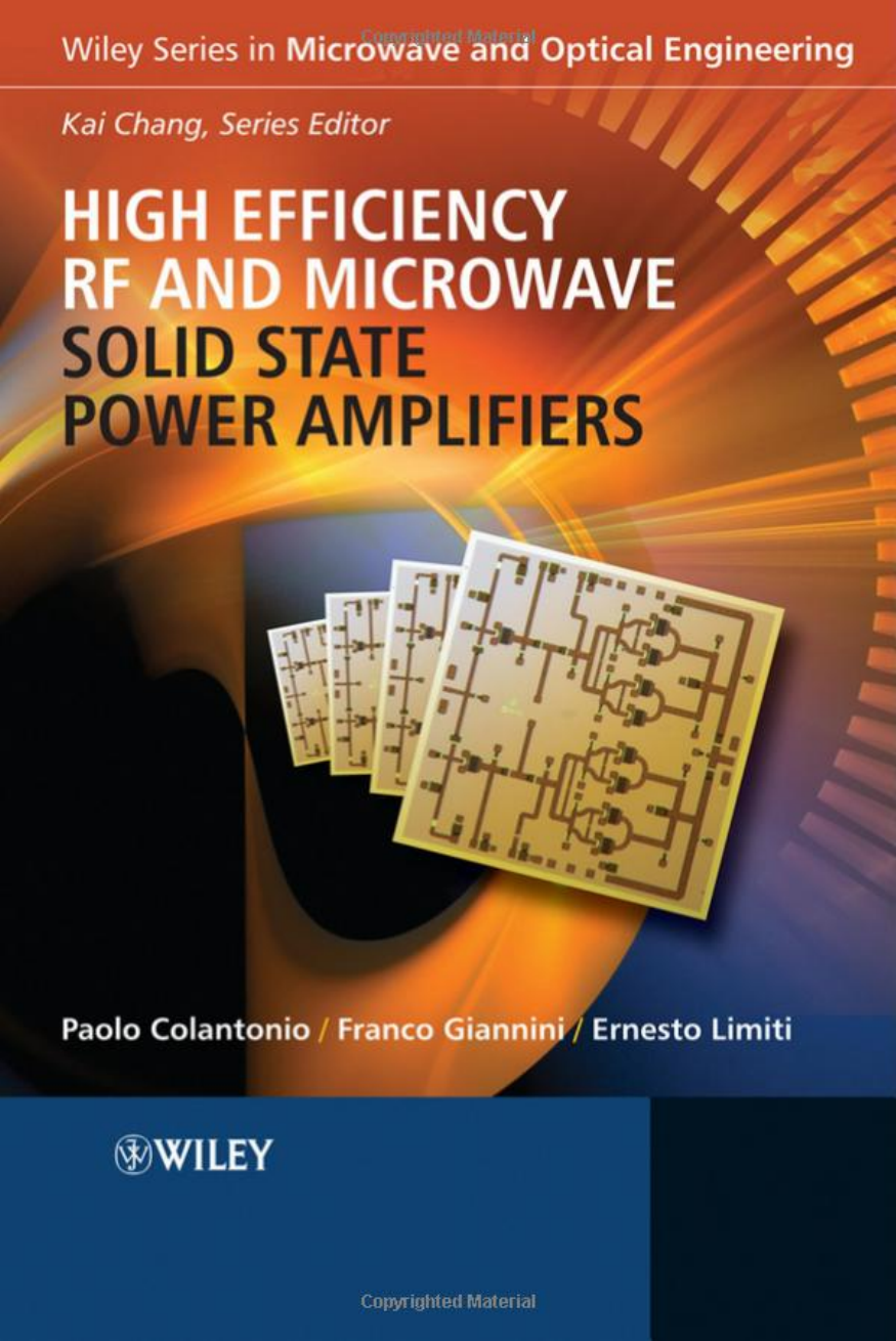
High Efficiency RF and Microwave Solid State Power Amplifiers Paolo Colantonio, Franco Giannini and Ernesto Limiti
© 2009 John Wiley & Sons, Ltd. ISBN: 978-0-470-51300-2
P1: OTE/OTE/SPH
FM
JWBK390/Colantonio
P2: OTE
July 2, 2009
21:18
Printer Name: Yet to Come
High Efficiency RF and Microwave
Solid State Power Amplifiers
Paolo Colantonio, Franco Giannini, and Ernesto Limiti
Department of Electronic Engineering, University of Roma,
Tor Vergata, Italy
A John Wiley and Sons, Ltd., Publication
�
P1: OTE/OTE/SPH
FM
JWBK390/Colantonio
P2: OTE
July 2, 2009
21:18
Printer Name: Yet to Come
This edition first published 2009.
C 2009 John Wiley & Sons Ltd
Registered office
John Wiley & Sons Ltd, The Atrium, Southern Gate, Chichester, West Sussex, PO19 8SQ, United Kingdom
For details of our global editorial offices, for customer services and for information about how to apply for
permission to reuse the copyright material in this book please see our website at www.wiley.com.
The right of the author to be identified as the author of this work has been asserted in accordance with the
Copyright, Designs and Patents Act 1988.
All rights reserved. No part of this publication may be reproduced, stored in a retrieval system, or transmitted, in
any form or by any means, electronic, mechanical, photocopying, recording or otherwise, except as permitted by
the UK Copyright, Designs and Patents Act 1988, without the prior permission of the publisher.
Wiley also publishes its books in a variety of electronic formats. Some content that appears in print may not be
available in electronic books.
Designations used by companies to distinguish their products are often claimed as trademarks. All brand names
and product names used in this book are trade names, service marks, trademarks or registered trademarks of their
respective owners. The publisher is not associated with any product or vendor mentioned in this book. This
publication is designed to provide accurate and authoritative information in regard to the subject matter covered. It
is sold on the understanding that the publisher is not engaged in rendering professional services. If professional
advice or other expert assistance is required, the services of a competent professional should be sought.
Library of Congress Cataloging-in-Publication Data
Colantonio, Paolo.
High efficiency RF and microwave solid state power amplifiers / Paolo Colantonio, Franco Giannini,
Ernesto Limiti.
p. cm.
Includes bibliographical references and index.
ISBN 978-0-470-51300-2 (cloth)
1. Power amplifiers.
2. Amplifiers, Radio frequency.
3. Microwave amplifiers.
4. Solid state electronics.
I. Giannini, Franco, 1944– II. Limiti, Ernesto.
III. Title.
TK7871.58.P6C65 2009
621.381
325–dc22
2009015213
A catalogue record for this book is available from the British Library.
ISBN 978-0-470-51300-2 (Hbk)
Typeset in 9/11pt Times by Aptara Inc., New Delhi, India.
Printed in Great Britain, by CPI Antony Rowe, Chippenham, Wiltshire
�
P1: OTE/OTE/SPH
FM
JWBK390/Colantonio
P2: OTE
July 2, 2009
21:18
Printer Name: Yet to Come
Contents
Preface
About the Authors
Acknowledgments
1 Power Amplifier Fundamentals
Introduction
1.1
1.2 Definition of Power Amplifier Parameters
1.3 Distortion Parameters
Intercept Point IPn
1.3.1 Harmonic Distortion
1.3.2 AM-AM/AM-PM
1.3.3 Two-tone Intermodulation
1.3.4
1.3.5 Carrier to Intermodulation Ratio
1.3.6 Spurious Free Dynamic Range
1.3.7 Adjacent Channel Power Ratio
1.3.8 Noise and Co-Channel Power Ratio (NPR and CCPR)
1.3.9 Multi-tone Intermodulation Ratio
1.3.10 Error Vector Magnitude
1.4 Power Match Condition
1.5 Class of Operation
1.6 Overview of Semiconductors for PAs
1.7 Devices for PA
1.7.1 Requirements for Power Devices
1.7.2 BJT
1.7.3 HBT
1.7.4 FET
1.7.5 MOSFET
1.7.6 LDMOS
1.7.7 MESFET
1.7.8 HEMT
1.7.9 General Remarks
1.8 Appendix: Demonstration of Useful Relationships
1.9 References
xi
xiii
xv
1
1
2
7
9
10
10
13
14
15
15
17
19
20
20
23
25
28
29
31
32
32
33
34
35
37
40
42
44
�
P1: OTE/OTE/SPH
FM
JWBK390/Colantonio
P2: OTE
July 2, 2009
21:18
Printer Name: Yet to Come
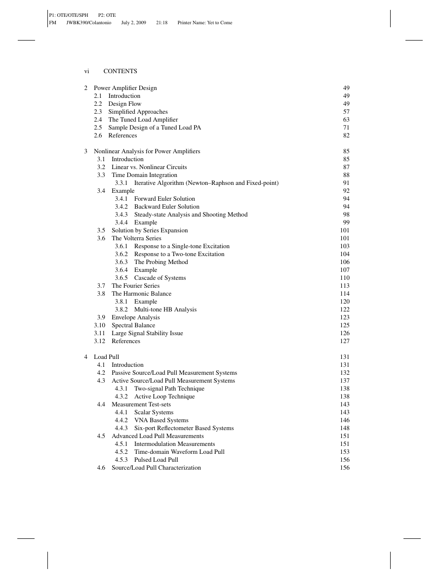
vi
CONTENTS
2 Power Amplifier Design
2.1 Introduction
2.2 Design Flow
2.3 Simplified Approaches
2.4 The Tuned Load Amplifier
2.5 Sample Design of a Tuned Load PA
2.6 References
3 Nonlinear Analysis for Power Amplifiers
3.1 Introduction
3.2 Linear vs. Nonlinear Circuits
3.3 Time Domain Integration
3.3.1
Iterative Algorithm (Newton–Raphson and Fixed-point)
3.4 Example
3.4.1 Forward Euler Solution
3.4.2 Backward Euler Solution
3.4.3 Steady-state Analysis and Shooting Method
3.4.4 Example
3.5 Solution by Series Expansion
3.6 The Volterra Series
3.6.1 Response to a Single-tone Excitation
3.6.2 Response to a Two-tone Excitation
3.6.3 The Probing Method
3.6.4 Example
3.6.5 Cascade of Systems
3.7 The Fourier Series
3.8 The Harmonic Balance
3.8.1 Example
3.8.2 Multi-tone HB Analysis
3.9 Envelope Analysis
3.10 Spectral Balance
3.11 Large Signal Stability Issue
3.12 References
4 Load Pull
4.1 Introduction
4.2 Passive Source/Load Pull Measurement Systems
4.3 Active Source/Load Pull Measurement Systems
4.3.1 Two-signal Path Technique
4.3.2 Active Loop Technique
4.4 Measurement Test-sets
4.4.1 Scalar Systems
4.4.2 VNA Based Systems
4.4.3 Six-port Reflectometer Based Systems
4.5 Advanced Load Pull Measurements
Intermodulation Measurements
4.5.1
4.5.2 Time-domain Waveform Load Pull
4.5.3 Pulsed Load Pull
4.6 Source/Load Pull Characterization
49
49
49
57
63
71
82
85
85
87
88
91
92
94
94
98
99
101
101
103
104
106
107
110
113
114
120
122
123
125
126
127
131
131
132
137
138
138
143
143
146
148
151
151
153
156
156
�
P1: OTE/OTE/SPH
FM
JWBK390/Colantonio
P2: OTE
July 2, 2009
21:18
Printer Name: Yet to Come
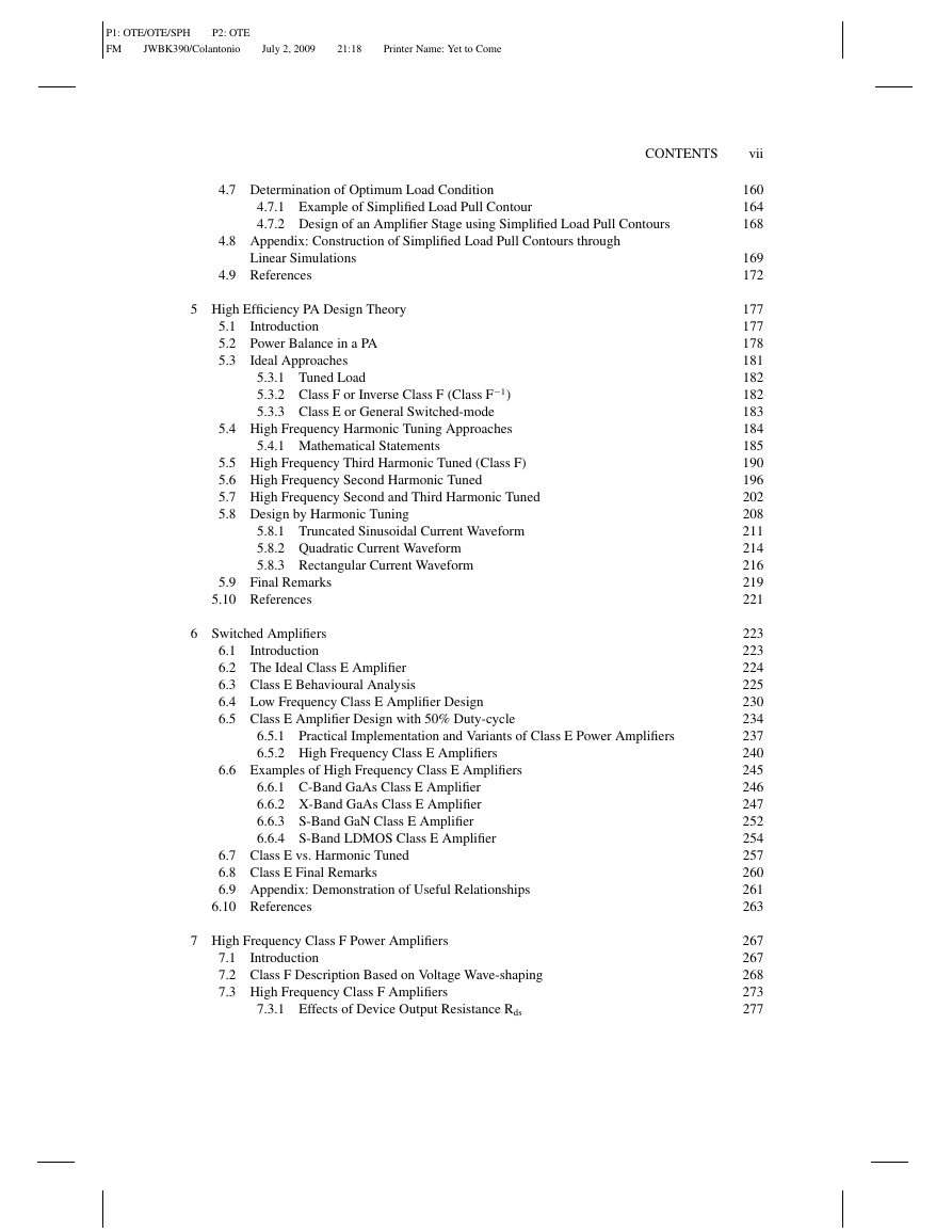
CONTENTS
vii
4.7 Determination of Optimum Load Condition
4.7.1 Example of Simplified Load Pull Contour
4.7.2 Design of an Amplifier Stage using Simplified Load Pull Contours
4.8 Appendix: Construction of Simplified Load Pull Contours through
Linear Simulations
4.9 References
5 High Efficiency PA Design Theory
5.1 Introduction
5.2 Power Balance in a PA
5.3 Ideal Approaches
5.3.1 Tuned Load
5.3.2 Class F or Inverse Class F (Class F
5.3.3 Class E or General Switched-mode
−1)
5.4 High Frequency Harmonic Tuning Approaches
5.4.1 Mathematical Statements
5.5 High Frequency Third Harmonic Tuned (Class F)
5.6 High Frequency Second Harmonic Tuned
5.7 High Frequency Second and Third Harmonic Tuned
5.8 Design by Harmonic Tuning
5.8.1 Truncated Sinusoidal Current Waveform
5.8.2 Quadratic Current Waveform
5.8.3 Rectangular Current Waveform
5.9 Final Remarks
5.10 References
6 Switched Amplifiers
6.1 Introduction
6.2 The Ideal Class E Amplifier
6.3 Class E Behavioural Analysis
6.4 Low Frequency Class E Amplifier Design
6.5 Class E Amplifier Design with 50% Duty-cycle
6.5.1 Practical Implementation and Variants of Class E Power Amplifiers
6.5.2 High Frequency Class E Amplifiers
6.6 Examples of High Frequency Class E Amplifiers
6.6.1 C-Band GaAs Class E Amplifier
6.6.2 X-Band GaAs Class E Amplifier
6.6.3 S-Band GaN Class E Amplifier
6.6.4 S-Band LDMOS Class E Amplifier
6.7 Class E vs. Harmonic Tuned
6.8 Class E Final Remarks
6.9 Appendix: Demonstration of Useful Relationships
6.10 References
7 High Frequency Class F Power Amplifiers
7.1 Introduction
7.2 Class F Description Based on Voltage Wave-shaping
7.3 High Frequency Class F Amplifiers
7.3.1 Effects of Device Output Resistance Rds
160
164
168
169
172
177
177
178
181
182
182
183
184
185
190
196
202
208
211
214
216
219
221
223
223
224
225
230
234
237
240
245
246
247
252
254
257
260
261
263
267
267
268
273
277
�
P1: OTE/OTE/SPH
FM
JWBK390/Colantonio
P2: OTE
July 2, 2009
21:18
Printer Name: Yet to Come
viii
CONTENTS
7.4 Bias Level Selection
7.5 Class F Output Matching Network Design
7.6 Class F Design Examples
7.7 References
8 High Frequency Harmonic Tuned Power Amplifiers
8.1 Introduction
8.2 Theory of Harmonic Tuned PA Design
8.3 Input Device Nonlinear Phenomena: Theoretical Analysis
8.4 Input Device Nonlinear Phenomena: Experimental Results
8.5 Output Device Nonlinear Phenomena
8.6 Design of a Second HT Power Amplifier
8.7 Design of a Second and Third HT Power Amplifier
8.8 Example of 2nd HT GaN PA
8.9 Final Remarks
8.10 References
9 High Linearity in Efficient Power Amplifiers
9.1 Introduction
9.2 Systems Classification
9.3 Linearity Issue
9.4 Bias Point Influence on IMD
9.5 Harmonic Loading Effects on IMD
9.5.1 High Linearity and High Efficiency PA Design Process
9.5.2 High Linearity and High Efficiency PA Design Example
9.6 Appendix: Volterra Analysis Example
9.7 References
10 Power Combining
Introduction
10.1
10.2 Device Scaling Properties
10.3 Power Budget
10.4 Power Combiner Classification
10.5 The T-junction Power Divider
10.5.1 Resistive Divider
10.6 Wilkinson Combiner
10.6.1 Two-way Equal Splitter Wilkinson Combiner/divider
10.6.2 Two-way Unequal Splitter Wilkinson Combiner/divider
10.6.3 Two-way Wilkinson with Arbitrary Impedances
10.6.4 Other Two-way Wilkinson Structures
10.6.5 Planarization of N-way Wilkinson Splitter/combiner
10.6.6 Design Considerations on Wilkinson Splitter/combiner
10.7 The Quadrature (90
) Hybrid
◦
10.7.1 Branch-line
10.7.2 Coupled Line Directional Couplers
10.7.3 The Lange Coupler
Hybrid (Ring Coupler or Rat-race)
◦
10.8 The 180
10.9 Bus-bar Combiner
280
286
289
295
297
297
298
303
309
316
321
328
335
336
339
341
341
342
345
347
352
354
358
362
365
369
369
370
371
373
377
379
380
383
385
386
387
388
391
395
395
400
404
405
407
�



 2023年江西萍乡中考道德与法治真题及答案.doc
 2012年重庆南川中考生物真题及答案.doc
 2013年江西师范大学地理学综合及文艺理论基础考研真题.doc
 2020年四川甘孜小升初语文真题及答案I卷.doc
 2020年注册岩土工程师专业基础考试真题及答案.doc
 2023-2024学年福建省厦门市九年级上学期数学月考试题及答案.doc
 2021-2022学年辽宁省沈阳市大东区九年级上学期语文期末试题及答案.doc
 2022-2023学年北京东城区初三第一学期物理期末试卷及答案.doc
 2018上半年江西教师资格初中地理学科知识与教学能力真题及答案.doc
 2012年河北国家公务员申论考试真题及答案-省级.doc
 2020-2021学年江苏省扬州市江都区邵樊片九年级上学期数学第一次质量检测试题及答案.doc
 2022下半年黑龙江教师资格证中学综合素质真题及答案.doc