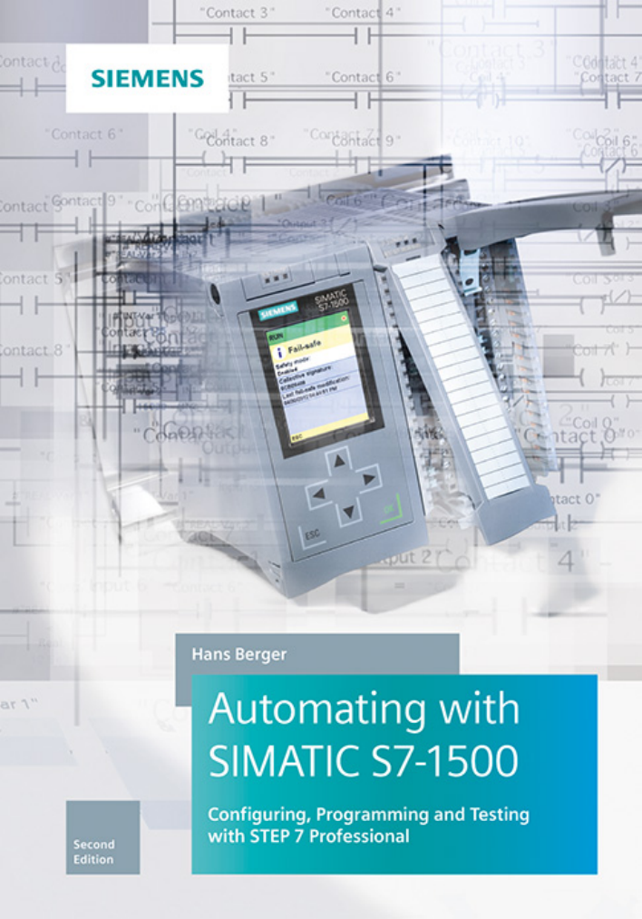
Cover
Automating with SIMATIC S7-1500
Preface
Imprint
Preface
The contents of the book at a glance
Table of contents
1 Introduction
1.1 Overview of the S7-1500 automation system
1.1.1 SIMATIC S7-1500 programmable controller
1.1.2 Overview of STEP 7 Professional
1.1.3 Various programming languages
1.1.4 Execution of the user program
1.1.5 Data management in the SIMATIC automation system
1.2 Introduction to STEP 7 Professional V14
1.2.1 Installing STEP 7
1.2.2 Automation License Manager
1.2.3 Starting STEP 7 Professional
1.2.4 Portal view
1.2.5 The windows of the Project view
1.2.6 Information system
1.2.7 Adapting the user interface
1.3 Editing a SIMATIC project
1.3.1 Structured representation of project data
1.3.2 Project data and editors for a PLC station
1.3.3 Working with projects
1.3.4 Working with reference projects
1.3.5 Working with libraries
1.3.6 Multilingual projects
2 SIMATIC S7-1500 automation system
2.1 S7-1500 station components
2.2 S7-1500 CPUs
2.2.1 CPU versions
2.2.2 Control and display elements
2.2.3 SIMATIC Memory Card
2.2.4 Bus interfaces
2.3 Signal modules
2.3.1 Digital input modules
2.3.2 Digital output modules
2.3.3 Digital input/output modules
2.3.4 Analog input modules
2.3.5 Analog output modules
2.3.6 Analog input/output modules
2.4 Technology modules
2.5 Communication modules
2.6 Further modules
2.6.1 System power supply modules
2.6.2 Load power supply modules
2.7 SIPLUS S7-1500
3 Device configuration
3.1 Introduction
3.2 Configuring a station
3.2.1 Adding a PLC station
3.2.2 Adding a module
3.3 Parameterization of modules
3.3.1 Parameterization of CPU properties
3.3.2 Addressing modules
3.3.3 Assigning parameters to signal modules
3.3.4 Configuring a configuration control
3.4 Configuring a network
3.4.1 Introduction
3.4.2 Networking a station
3.4.3 Node addresses in a subnet
3.4.4 Communication services and types of connection
3.4.5 Configuring a connection
3.4.6 Configuring a PROFINET subnet
3.4.7 Configuring a PROFIBUS subnet
4 Tags, addressing, and data types
4.1 Operands and tags
4.1.1 Introduction, overview
4.1.2 Operand areas: inputs and outputs
4.1.3 Operand area bit memory
4.1.4 Operand area: data
4.1.5 Operand area: temporary local data
4.2 Addressing of tags and constants
4.2.1 Signal path
4.2.2 Absolute addressing
4.2.3 Symbolic addressing
4.2.4 Addressing a tag part
4.2.5 Addressing a constant
4.2.6 Indirect addressing
4.3 Addressing of hardware objects
4.4 General information on data types
4.4.1 Overview of data types
4.4.2 Implicit data type conversion
4.4.3 Overlaying tags (data type views)
4.5 Elementary data types
4.5.1 Bit-serial data types BOOL, BYTE, WORD, DWORD, and LWORD
4.5.2 BCD numbers BCD16 and BCD32
4.5.3 Data types CHAR and WCHAR
4.5.4 Fixed-point data types without sign USINT, UINT, UDINT, ULINT
4.5.5 Fixed-point data types with sign SINT, INT, DINT, and LINT
4.5.6 Floating-point data types REAL and LREAL
4.5.7 Data types for durations
4.5.8 Data types for points in time
4.6 Structured data types
4.6.1 Date and time DATE_AND_TIME (DT)
4.6.2 Date and time DATE_AND_LTIME (DTL)
4.6.3 Strings STRING and WSTRING
4.6.4 Data type ARRAY
4.6.5 Data type STRUCT
4.7 Parameter types
4.7.1 Overview
4.7.2 Parameter types BLOCK_FC and BLOCK_FB (STL)
4.7.3 Parameter type DB_ANY
4.7.4 Parameter type VOID
4.7.5 Parameter types POINTER, ANY, and VARIANT
4.7.6 Parameter type ARRAY[*]
4.8 Pointer
4.8.1 Introduction
4.8.2 Area pointer
4.8.3 DB pointer
4.8.4 ANY pointer
4.9 PLC data types
4.9.1 Programming a PLC data type
4.9.2 Using a PLC data type
4.9.3 Comparing PLC data types
4.9.4 Renumbering a PLC data type
4.10 System data types
4.10.1 System data types for timer functions
4.10.2 System data types for counter functions
4.10.3 Start information
4.11 Hardware data types
5 Executing the user program
5.1 Operating states
5.1.1 STOP operating state
5.1.2 Operating mode STARTUP
5.1.3 RUN operating state
5.1.4 Retentive behavior of operands
5.2 Creating a user program
5.2.1 Program execution
5.2.2 Structuring of the user program
5.2.3 Block types
5.2.4 Block properties
5.2.5 Block interface
5.2.6 Calling a code block
5.2.7 Programming recommendations
5.3 Startup program
5.3.1 Organization blocks for the startup program
5.3.2 Resetting retentive data
5.3.3 Determining a module address
5.3.4 Parameterization of modules
5.4 Main program
5.4.1 Organization blocks for the main program
5.4.2 Process image updating
5.4.3 Cycle time
5.4.4 Response time
5.4.5 Stopping and delaying the program
5.4.6 Time
5.4.7 Read system time
5.4.8 Runtime meter
5.5 Interrupt processing
5.5.1 Introduction to interrupt processing
5.5.2 Time-of-day interrupts
5.5.3 Time-delay interrupts
5.5.4 Cyclic interrupts
5.5.5 Hardware interrupts
5.5.6 Assigning interrupts during runtime
5.5.7 Reading additional interrupt information
5.6 Error handling, diagnostics
5.6.1 Causes of errors and error responses
5.6.2 Local error handling
5.6.3 Global error handling (synchronous error)
5.6.4 Enabling and disabling synchronous error processing
5.6.5 Asynchronous errors
5.6.6 Disable, delay, and enable interrupts and asynchronous errors
5.7 Diagnostics in the user program
5.7.1 Diagnostic error interrupt
5.7.2 Read start information
5.7.3 Reading runtime information
5.7.4 Diagnostic functions in the user program
5.8 Configuring alarms
5.8.1 Introduction
5.8.2 Configuring alarms according to the alarm number procedure
5.8.3 System blocks for alarms
5.8.4 Generating a user diagnostics alarm
5.8.5 CPU alarm display
6 Program editor
6.1 Introduction
6.2 PLC tag table
6.2.1 Creating and editing a PLC tag table
6.2.2 Defining and processing PLC tags
6.2.3 Comparing PLC tag tables
6.2.4 Exporting and importing a PLC tag table
6.2.5 Constants tables
6.3 Programming a code block
6.3.1 Creating a new code block
6.3.2 Working area of the program editor for code blocks
6.3.3 Specifying code block properties
6.3.4 Protecting a block
6.3.5 Programming a block interface
6.3.6 General procedure when programming the control function
6.3.7 Programming a control function with LAD and FBD
6.3.8 Programming control functions with SCL
6.3.9 Programming control functions with STL
6.3.10 Programming of a control function with GRAPH
6.4 Programming a data block
6.4.1 Creating a new data block
6.4.2 Working area of program editor for data blocks
6.4.3 Defining properties for data blocks
6.4.4 Declaring data tags
6.4.5 Entering data tags in global data blocks
6.5 Compiling blocks
6.5.1 Starting the compilation
6.5.2 Compiling SCL blocks
6.5.3 Eliminating errors following compilation
6.6 Working with source files
6.7 Program information
6.7.1 Cross-reference list
6.7.2 Assignment list
6.7.3 Call structure
6.7.4 Dependency structure
6.7.5 Consistency check
6.7.6 Memory utilization of the CPU
7 Ladder logic LAD
7.1 Introduction
7.1.1 Programming with LAD in general
7.1.2 Program elements of ladder logic
7.2 Programming binary logic operations with LAD
7.2.1 NO and NC contacts
7.2.2 Series and parallel connection of contacts
7.2.3 T branch, open parallel branch
7.2.4 Negate result of logic operation in the ladder logic
7.2.5 Edge evaluation of a binary tag in the ladder logic
7.2.6 Validity check of a floating-point tag in the ladder logic
7.2.7 Comparison contacts
7.3 Programming memory functions with LAD
7.3.1 Simple and negating coils
7.3.2 Set and reset coils
7.3.3 Retentive response due to latching
7.3.4 Edge evaluation with pulse output in the ladder logic
7.3.5 Multiple setting and resetting (filling the bit array) in the ladder logic
7.3.6 Coils with time response
7.4 Programming Q boxes with LAD
7.4.1 Memory boxes in the ladder logic
7.4.2 Edge evaluation of current flow
7.4.3 Timer functions in the ladder logic
7.4.4 Counter functions in the ladder logic
7.5 Programming EN/ENO boxes with LAD
7.5.1 Edge evaluation with an EN/ENO box
7.5.2 Transfer functions in the ladder logic
7.5.3 Arithmetic functions in the ladder logic
7.5.4 Math functions in the ladder logic
7.5.5 Conversion functions in the ladder logic
7.5.6 Shift functions in the ladder logic
7.5.7 Logic functions in the ladder logic
7.5.8 Functions for strings in the ladder logic
7.6 Programming VARIANT functions with LAD
7.7 Program control with LAD
7.7.1 Jump functions in the ladder logic
7.7.2 Block end function in the ladder logic
7.7.3 Block call functions in the ladder logic
8 Function block diagram FBD
8.1 Introduction
8.1.1 Programming with FBD in general
8.1.2 Program elements of the function block diagram
8.2 Programming binary logic operations with FBD
8.2.1 Scanning for signal states "1" and "0"
8.2.2 Programming a binary logic operation in the function block diagram
8.2.3 AND function in the function block diagram
8.2.4 OR function in the function block diagram
8.2.5 Exclusive OR function in the function block diagram
8.2.6 Combined binary logic operations, negating result of logic operation
8.2.7 T branch in the function block diagram
8.2.8 Edge evaluation of binary tags in the function block diagram
8.2.9 Validity checking of floating-point numbers in the function block diagram
8.2.10 Comparison functions in the function block diagram
8.3 Programming standard boxes with FBD
8.3.1 Assignment and negating assignment
8.3.2 Set and reset boxes
8.3.3 Edge evaluation with pulse output in the function block diagram
8.3.4 Multiple setting and resetting (filling the bit array) in the function block diagram
8.3.5 Standard boxes with time response
8.4 Programming Q boxes with FBD
8.4.1 Memory boxes in the function block diagram
8.4.2 Edge evaluation of the result of logic operation in the function block diagram
8.4.3 Timer functions in the function block diagram
8.4.4 Counter functions in the function block diagram
8.5 Programming EN/ENO boxes with FBD
8.5.1 Edge evaluation with an EN/ENO box
8.5.2 Transfer functions in the function block diagram
8.5.3 Arithmetic functions in the function block diagram
8.5.4 Math functions in the function block diagram
8.5.5 Conversion functions in the function block diagram
8.5.6 Shift functions in the function block diagram
8.5.7 Logic functions in the function block diagram
8.5.8 Functions for strings in the function block diagram
8.6 Programming VARIANT functions with FBD
8.7 Program control with FBD
8.7.1 Jump functions in the function block diagram
8.7.2 Block end function in the function block diagram
8.7.3 Block call functions in the function block diagram
9 Structured Control Language SCL
9.1 Introduction
9.1.1 Programming with SCL in general
9.1.2 SCL statements and operators
9.2 Programming binary logic operations with SCL
9.2.1 Scanning for signal states "1" and "0"
9.2.2 AND function in SCL
9.2.3 OR function in SCL
9.2.4 Exclusive OR function in SCL
9.2.5 Combined binary logic operations in SCL
9.2.6 Negate result of logic operation in SCL
9.3 Programming memory functions with SCL
9.3.1 Value assignment of a binary tag
9.3.2 Setting and resetting in SCL
9.3.3 Edge evaluation in SCL
9.4 Programming timer and counter functions with SCL
9.4.1 IEC timer functions in SCL
9.4.2 Counter functions in SCL
9.5 Programming digital functions with SCL
9.5.1 Transfer function, value assignment of a digital tag
9.5.2 Comparison functions in SCL
9.5.3 Arithmetic functions in SCL
9.5.4 Math functions in SCL
9.5.5 Conversion functions in SCL
9.5.6 Shift functions in SCL
9.5.7 Word logic operations, logic expression in SCL
9.5.8 Functions for strings in SCL
9.6 Programming VARIANT functions with SCL
9.7 Program control with SCL
9.7.1 Control statements
9.7.2 Block end function for SCL
9.7.3 Calling a function (FC) with SCL
9.7.4 Call of a function block (FB) with SCL
9.7.5 Supply of parameters
10 Statement list STL
10.1 Introduction
10.1.1 Programming with STL in general
10.1.2 Structure of an STL statement
10.1.3 Entering an STL statement
10.1.4 Addressing of 64-bit tags
10.1.5 STL networks in LAD and FBD blocks
10.2 Programming binary logic operations with STL
10.2.1 Processing of a binary logic operation, operation step
10.2.2 Scanning for signal states "1" and "0"
10.2.3 AND function in the statement list
10.2.4 OR function in the statement list
10.2.5 Exclusive OR function in the statement list
10.2.6 Combined binary logic operations in the statement list
10.2.7 Control of result of logic operation
10.3 Programming memory functions with STL
10.3.1 Assignment in the statement list
10.3.2 Setting and resetting in the statement list
10.3.3 Edge evaluation in the statement list
10.4 Programming timer and counter functions with STL
10.4.1 Timer functions in the statement list
10.4.2 Counter functions in the statement list
10.5 Programming digital functions with STL
10.5.1 Transfer functions in the statement list
10.5.2 Comparison functions in the statement list
10.5.3 Arithmetic functions in the statement list
10.5.4 Math functions in the statement list
10.5.5 Conversion functions in the statement list
10.5.6 Shift functions in the statement list
10.5.7 Word logic operations in the statement list
10.5.8 Functions for strings in the statement list
10.6 Programming VARIANT functions with STL
10.7 Program control with STL
10.7.1 Jump functions in the statement list
10.7.2 Block end functions in the statement list
10.7.3 Block call function in the statement list
10.8 Further STL functions
10.8.1 Working with status bits
10.8.2 Accumulator functions
10.8.3 Working with the data block registers
10.8.4 Partial addressing of data operands
10.8.5 Absolute addressing of temporary local data
10.8.6 Working with the address registers
10.8.7 Memory-indirect addressing
10.8.8 Register-indirect addressing
10.8.9 Direct access to complex local tags
10.8.10 Null instructions
11 S7-GRAPH sequential control
11.1 Introduction
11.1.1 What is a sequential control?
11.1.2 Properties of a sequential control
11.2 Elements of a sequential control
11.2.1 Steps and transitions
11.2.2 Jumps in a sequential control
11.2.3 Branching of a sequencer
11.2.4 Permanent instructions
11.2.5 Step and transition functions
11.2.6 Processing of conditions
11.2.7 Processing of actions
11.3 Configuring a sequential control
11.3.1 General procedure for configuration
11.3.2 Programming the GRAPH function block
11.3.3 Configuring the sequencer structure
11.3.4 Programming steps and transitions
11.3.5 Programming permanent instructions
11.3.6 Configuring alarms
11.3.7 Attributes of the GRAPH function block
11.3.8 Calling the GRAPH function block
11.4 Testing the sequential control
11.4.1 Loading the GRAPH function block
11.4.2 Settings for program testing
11.4.3 Using operating modes
11.4.4 Synchronization of a sequencer
11.4.5 Testing with program status
12 Basic functions
12.1 Binary logic operations
12.1.1 Introduction
12.1.2 Working with binary signals
12.1.3 AND function, series connection
12.1.4 OR function, parallel connection
12.1.5 Exclusive OR function, non-equivalence function
12.1.6 Negate result of logic operation, NOT contact
12.2 Memory functions
12.2.1 Introduction
12.2.2 Simple and negating coil, assignment
12.2.3 Single setting and resetting
12.2.4 Multiple setting and resetting
12.2.5 Dominant setting and resetting, memory boxes
12.3 Edge evaluation
12.3.1 Principle of operation of an edge evaluation
12.3.2 Edge evaluation of a binary tag (LAD, FBD)
12.3.3 Edge evaluation with pulse output (LAD, FBD)
12.3.4 Edge evaluation with a Q box (LAD, FBD)
12.3.5 Edge evaluation with an EN/ENO box (LAD, FBD)
12.3.6 Edge evaluation with SCL
12.3.7 Edge evaluation with STL
12.4 Timer functions
12.4.1 Adding a timer function
12.4.2 Pulse generation TP
12.4.3 ON delay TON
12.4.4 OFF delay TOF
12.4.5 Accumulating ON delay TONR
12.4.6 Loading a timer function with a duration
12.4.7 Resetting a timer function
12.5 Counter functions
12.5.1 Inserting a counter function
12.5.2 Up counter CTU
12.5.3 Down counter CTD
12.5.4 Up/down counter CTUD
13 Digital functions
13.1 Transfer functions
13.1.1 Copy tag, MOVE and S_MOVE box for LAD and FBD
13.1.2 Value assignments with SCL
13.1.3 Loading and transferring with STL
13.1.4 Copy tag, MOVE and S_MOVE with STL
13.1.5 Reading and writing a VARIANT tag
13.1.6 Copy data area with MOVE_BLK_VARIANT
13.1.7 Copy data area with MOVE_BLK and UMOVE_BLK
13.1.8 Filling a data area with FILL_BLK an UFILL_BLK
13.1.9 Transferring a tag from and to a BYTE array
13.1.10 Reading and writing with PEEK and POKE (SCL, STL)
13.1.11 Changing a byte sequence with SWAP
13.1.12 Determining range limits
13.2 Comparison functions
13.2.1 Execution of comparison functions
13.2.2 Range comparison with LAD and FBD
13.2.3 Testing the floating-point tag, OK contact, OK box
13.2.4 Testing a VARIANT pointer with LAD, FBD, and STL
13.2.5 Testing a VARIANT pointer with SCL
13.3 Arithmetic functions
13.3.1 Arithmetic functions for numerical values
13.3.2 Arithmetic functions for time values
13.3.3 Decrementing and incrementing
13.4 Math functions
13.4.1 General function description
13.4.2 Trigonometric functions SIN, COS, TAN
13.4.3 Arc functions ASIN, ACOS, ATAN
13.4.4 Generate square and extract square root
13.4.5 Logarithm and power
13.4.6 Extract decimal points, generate absolute value and negation
13.4.7 Calculating with the CALCULATE box in LAD and FBD
13.5 Conversion functions
13.5.1 Conversion functions CONV, S_CONV and T_CONV
13.5.2 Conversion of DB_ANY
13.5.3 Conversion functions for floating-point numbers
13.5.4 Conversion functions STRG_TO_CHARS and CHARS_TO_STRG
13.5.5 Conversion functions STRG_VAL and VAL_STRG
13.5.6 Conversion functions ATH and HTA
13.5.7 Conversion functions SCALE_X and NORM_X
13.6 Shift functions
13.6.1 General function description
13.6.2 Shift to right SHR
13.6.3 Shift to left SHL
13.6.4 Rotate to right ROR
13.6.5 Rotate to left ROL
13.7 Logic functions
13.7.1 Word logic operations
13.7.2 Invert, generate one's complement
13.7.3 Coding functions DECO and ENCO
13.7.4 Selection functions SEL, MUX, and DEMUX
13.7.5 Minimum selection MIN, maximum selection MAX
13.7.6 Limiter LIMIT
13.8 Editing strings
13.9 Read symbol name
14 Program control
14.1 Jump functions
14.1.1 Introduction
14.1.2 Absolute jump
14.1.3 Conditional jump
14.1.4 Jump list
14.1.5 Jump distributor
14.1.6 Loop jump
14.2 Block end functions
14.2.1 Block end function RET (LAD and FBD)
14.2.2 RETURN statement (SCL)
14.2.3 Block end functions BEC, BEU, and BE (STL)
14.3 Calling of code blocks
14.3.1 Introduction
14.3.2 Calling a function FC
14.3.3 Calling a function block FB
14.3.4 Asynchronously working system blocks
14.3.5 EN/ENO mechanism
14.4 Working with blocks
14.4.1 Blocks with optimized and standard access
14.4.2 Data types of the local tags
14.4.3 Addressing block parameters
14.4.4 Supplying the block parameters
14.4.5 Transfer of block parameters
14.5 Data block functions
14.5.1 Read data block attributes
14.5.2 Reading and writing the load memory
14.5.3 ARRAY data blocks
14.5.4 System blocks for access to ARRAY data blocks
14.5.5 CPU data blocks
15 Online mode, diagnostics and test
15.1 Connecting a PLC station online
15.1.1 Connection of a programming device to the PLC station
15.1.2 Resetting the CPU memory
15.1.3 Reset to factory settings
15.2 Transferring project data
15.2.1 Loading project data for the first time
15.2.2 Reloading the project data
15.2.3 Protecting the user program
15.2.4 Working with online project data
15.2.5 Working with the memory card
15.3 Working with blocks in online mode
15.3.1 Introduction
15.3.2 Editing an online block
15.3.3 Loading and uploading a block
15.3.4 Download without reinitialization
15.3.5 Working with snapshots
15.3.6 Working with setpoints
15.3.7 Comparing blocks
15.4 Hardware diagnostics
15.4.1 Status displays on the modules
15.4.2 Diagnostics window
15.4.3 Diagnostic buffer
15.4.4 Online tools
15.4.5 Further diagnostic information via the programming device
15.5 Testing the user program
15.5.1 Defining the call environment
15.5.2 Testing with program status
15.5.3 Monitoring of PLC tags
15.5.4 Monitoring and controlling of data tags
15.5.5 Testing with watch tables
15.5.6 Testing with the force table
15.6 Measured value recording with the trace function
15.6.1 Introduction
15.6.2 Creating the trace configuration
15.6.3 Recording measured values
16 Distributed I/O
16.1 Introduction, overview
16.2 ET 200 distributed IO system
16.2.1 ET 200MP
16.2.2 ET 200M
16.2.3 ET 200SP
16.2.4 ET 200S
16.2.5 ET 200pro
16.2.6 ET 200AL
16.2.7 ET 200eco and ET200eco PN
16.3 PROFINET IO
16.3.1 PROFINET IO components
16.3.2 Addresses with PROFINET IO
16.3.3 Configuring PROFINET IO
16.3.4 Coupling modules for PROFINET IO
16.3.5 Real-time communication in PROFINET
16.3.6 Special PROFINET configurations
16.4 PROFIBUS DP
16.4.1 PROFIBUS DP components
16.4.2 Addresses with PROFIBUS DP
16.4.3 Configuring PROFIBUS DP
16.4.4 Coupling modules for PROFIBUS DP
16.4.5 Special PROFIBUS configurations
16.5 System blocks for distributed I/O
16.5.1 Reading and writing I/O data
16.5.2 Read diagnostic data from a DP standard slave
16.5.3 Receive and provide a data record
16.5.4 Activate/deactivate distributed station
16.5.5 Reconfiguring a PROFINET IO system
16.6 DPV1 interrupts
16.7 Isochronous mode
16.7.1 Introduction
16.7.2 Isochronous mode with PROFINET IO
16.7.3 Isochronous mode with PROFIBUS
16.7.4 Isochronous mode interrupt
16.7.5 Isochronous process image updating
17 Communication
17.1 Overview
17.2 Open user communication
17.2.1 Basics
17.2.2 Data structure of open user communication
17.2.3 Establish connection and send data with TSEND_C
17.2.4 Establish connection and receive data with TRCV_C
17.2.5 Configuring open user communication
17.2.6 Further functions for open user communication
17.3 S7 communication
17.3.1 Basics
17.3.2 One-way data exchange
17.3.3 Two-way data exchange
17.3.4 Configuring S7 communication
17.4 Freeport communication
17.4.1 Introduction to Freeport communication
17.4.2 Configuring the CM PtP communication module
17.4.3 Freeport communication functions
17.5 Further communication functions
17.5.1 USS protocol for drives
17.5.2 Modbus RTU
17.5.3 Modbus TCP
18 Appendix
18.1 Migrating a project
18.2 Web server
18.2.1 Enable Web server
18.2.2 Standard Web pages
18.2.3 Basic websites
18.2.4 Read out service data
18.2.5 Initialize Web server and synchronize Web pages (WWW)
18.3 Technology objects
18.3.1 Technology objects for motion control
18.3.2 Technology objects for PID control
18.3.3 Technology objects for counting and measuring
18.4 Data logging and transferring recipes
18.4.1 Introduction to data logging
18.4.2 Using data logging
18.4.3 Functions for data logging
18.4.4 Introduction to recipe transfer
18.4.5 Functions for the recipe transfer
18.5 Simulation with S7-PLCSIM
18.5.1 S7-PLCSIM in general
18.5.2 The PLCSIM user interface
18.5.3 Testing in S7-PLCSIM with STEP-7 test functions
18.5.4 Working with a simulation project
18.5.5 Testing with the address area
18.5.6 Testing with the SIM table
18.5.7 Testing with the sequence table
18.6 Machine and plant diagnostics with ProDiag
Index
Further books from Publicis Publishing


 2023年江西萍乡中考道德与法治真题及答案.doc
 2012年重庆南川中考生物真题及答案.doc
 2013年江西师范大学地理学综合及文艺理论基础考研真题.doc
 2020年四川甘孜小升初语文真题及答案I卷.doc
 2020年注册岩土工程师专业基础考试真题及答案.doc
 2023-2024学年福建省厦门市九年级上学期数学月考试题及答案.doc
 2021-2022学年辽宁省沈阳市大东区九年级上学期语文期末试题及答案.doc
 2022-2023学年北京东城区初三第一学期物理期末试卷及答案.doc
 2018上半年江西教师资格初中地理学科知识与教学能力真题及答案.doc
 2012年河北国家公务员申论考试真题及答案-省级.doc
 2020-2021学年江苏省扬州市江都区邵樊片九年级上学期数学第一次质量检测试题及答案.doc
 2022下半年黑龙江教师资格证中学综合素质真题及答案.doc