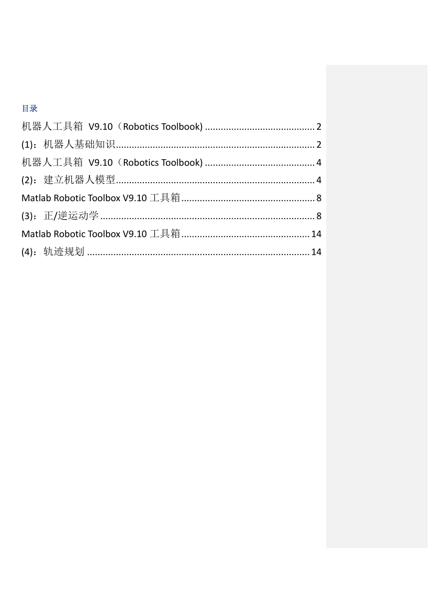
目录
机器人工具箱 V9.10(Robotics Toolbook) .......................................... 2
(1):机器人基础知识 ............................................................................ 2
机器人工具箱 V9.10(Robotics Toolbook) .......................................... 4
(2):建立机器人模型 ............................................................................ 4
Matlab Robotic Toolbox V9.10 工具箱 ................................................... 8
(3):正/逆运动学 .................................................................................. 8
Matlab Robotic Toolbox V9.10 工具箱 ................................................. 14
(4):轨迹规划 ..................................................................................... 14
�
机器人工具箱 V9.10(Robotics Toolbook)
(1):机器人基础知识
General/Rotations
批注 [A1]: 也可以通过在 MATLAB 中
输入 rtbdemo 来进行学习
Matlab Robotic Toolbox 工具箱学习
笔记根据 Robot Toolbox
demonstrations 目录,将分三大部分
阐述:
1、
(1) R = rotx(pi/2); 绕 x 轴旋转 pi/2 得到的旋转矩阵 (三维矩阵)(弧度)
General(Rotations,Transformations,Tr
R = rotx(30, 'deg') * roty(50, 'deg') * rotz(10, 'deg'); r=rotx(theta, ‘deg’) matlab 默认的角度
ajectory)
单位为弧度,这里可以用度数作为单位
(2) [theta,vec] = tr2angvec(R); theta 以角度作为单位,求出 R 等效的任意旋转变换的旋转轴矢
量 vec 和转角 theta
(3) eul = tr2eul(R); 旋转矩阵用欧拉角表示,R = rotz(a)*roty(b)*rotz(c)
(4) rpy = tr2rpy(R); 旋转矩阵用 roll-pitch-yaw 角表示, R = rotx(r)*roty(p)*rotz(y)
(5) q = Quaternion(R); 旋转矩阵用四元数表示
(6) q.R; 将四元数转化为旋转矩阵
(7)tripleangle('rpy'); 界面,可以是“rpy”,“eluer”角度单位为度。
2、Arm(Robot,Animation,Forwarw
kinematics,Inverse
kinematics,Jacobians,Inverse
dynamics,Forward
dynamics,Symbolic,Code generation)
3、Mobile(Driving to a
pose,Quadrotor,Braitenberg,Bug,D*,P
RM,SLAM,Particle filter)
�
General/Transformations
(1)t = transl(0.5, 0.0, 0.0) * troty(pi/2) * trotz(-pi/2) %沿 x 轴平移 0.5,绕 y 轴旋转 pi/2,绕 z 轴旋转-pi/2
平移算子
(2)t=trotx(pi/2), troty(pi/2), trotz(pi/2)旋转算子
(3)tr2eul(t) %将齐次变换矩阵转化为欧拉角
(4)tr2rpy(t) %将齐次变换矩阵转化为 roll、pitch、yaw 角
Transl()平移矩阵函数
General/Trajectory
>> p=[ 1 2 3]
p =
1 2 3
>> transl(p)
ans =
1 0 0 1
0 1 0 2
0 0 1 3
0 0 0 1
>> transl(ans)
ans =
1
2
3
>> trotx(pi)
ans =
1.0000 0 0 0
0 -1.0000 -0.0000 0
0 0.0000 -1.0000 0
0 0 0 1.0000
>> rotx(pi)
ans =
1.0000 0 0
0 -1.0000 -0.0000
0 0.0000 -1.0000
clear;
clc;
p0 = -1;% 定义初始点及终点位置
p1 = 2;
p = tpoly(p0, p1, 50);% 取步长为 50
figure(1);
plot(p);%绘图,可以看到在初始点及终点的一、二阶导均为零
[p,pd,pdd] = tpoly(p0, p1, 50);%得到位置、速度、加速度
%p 为五阶多项式,速度、加速度均在一定范围内
figure(2);
subplot(3,1,1); plot(p); xlabel('Time'); ylabel('p');
subplot(3,1,2); plot(pd); xlabel('Time'); ylabel('pd');
subplot(3,1,3); plot(pdd); xlabel('Time'); ylabel('pdd');
%另外一种方法:
[p,pd,pdd] = lspb(p0, p1, 50);
figure(3);
subplot(3,1,1); plot(p); xlabel('Time'); ylabel('p');
subplot(3,1,2); plot(pd); xlabel('Time'); ylabel('pd');% 可看到速度呈梯形
subplot(3,1,3); plot(pdd); xlabel('Time'); ylabel('pdd');
%三维的情况:
p = mtraj(@tpoly, [0 1 2], [2 1 0], 50);
figure(4);
plot(p)
%对于齐次变换矩阵的情况
T0 = transl(0.4, 0.2, 0) * trotx(pi);% 定义初始点和目标点的位姿
T1 = transl(-0.4, -0.2, 0.3) * troty(pi/2) * trotz(-pi/2);
T = ctraj(T0, T1, 50);
first=T(:,:,1);%初始位姿矩阵
tenth=T(:,:,10);%第十个位姿矩阵
figure(5);
tranimate(T);%动画演示坐标系自初始点运动到目标点的过程
批注 [A2]:
典型用法:
五次多项式轨迹规划
[p,pd,pdd] = tpoly(p0, p1, 50);
subplot(3,1,1); plot(p); xlabel('Time'
); ylabel('p');
subplot(3,1,2); plot(pd); xlabel('Tim
e'); ylabel('pd');
subplot(3,1,3); plot(pdd); xlabel('Ti
me'); ylabel('pdd');
也可以
[S,SD,SDD] = tpoly(S0, SF, N, SD0
, SDF)
SD0 为初始速度,SDF 为最终速度
S0 为起点位置,SF 为终点位置,N
为步数
批注 [A3]:
典型用法:
抛物线轨迹规划
[p,pd,pdd] = lspb(p0, p1, 50);
subplot(3,1,1); plot(p); xlabel('Time'
); ylabel('p');
subplot(3,1,2); plot(pd); xlabel('Tim
e'); ylabel('pd');
subplot(3,1,3); plot(pdd); xlabel('Ti
me'); ylabel('pdd');
也可以
[S,SD,SDD] = LSPB(S0, SF, M, V)
V 为限定的最大速度
批注 [A4]:
P1,P2 可以是旋转矩阵,齐次矩阵
和 4 元数这几个形式任意一个
'fps', fps fps 的值可以改变动画的
速度(默认 10)
'nsteps', n n 是插入的中间点个数
(默认 50)
'axis',A 坐标系限制
A=[xmin, xmax, ymin, ymax, zmin,
zmax]
'movie',M Save frames as files i
n the folder M
ctraj() 笛卡尔空间轨迹规划函数
可以显示从 P1 变到 p2 的动画
tranimate((P1, P2, OPTIONS)
一维轨迹生成:
tpoly---五次多项式轨迹规划
Options:
lspb---抛物线轨迹规划
�
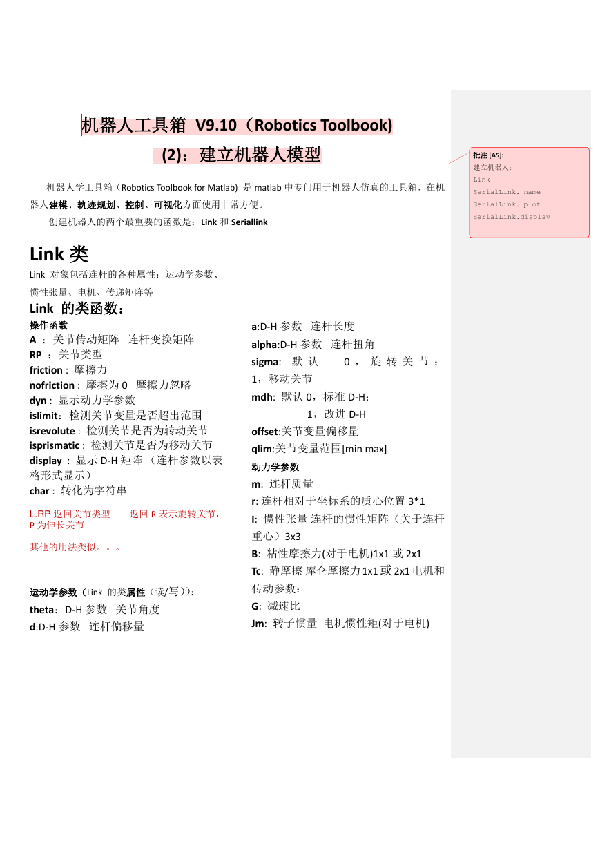
机器人工具箱 V9.10(Robotics Toolbook)
(2):建立机器人模型
机器人学工具箱(Robotics Toolbook for Matlab) 是 matlab 中专门用于机器人仿真的工具箱,在机
器人建模、轨迹规划、控制、可视化方面使用非常方便。
创建机器人的两个最重要的函数是:Link 和 Seriallink
批注 [A5]:
建立机器人:
Link
SerialLink. name
SerialLink. plot
SerialLink.display
Link 类
Link 对象包括连杆的各种属性:运动学参数、
惯性张量、电机、传递矩阵等
Link 的类函数:
操作函数
A :关节传动矩阵 连杆变换矩阵
RP :关节类型
friction : 摩擦力
nofriction : 摩擦为 0 摩擦力忽略
dyn : 显示动力学参数
islimit:检测关节变量是否超出范围
isrevolute : 检测关节是否为转动关节
isprismatic : 检测关节是否为移动关节
display : 显示 D-H 矩阵 (连杆参数以表
格形式显示)
char : 转化为字符串
L.RP 返回关节类型 返回 R 表示旋转关节,
P 为伸长关节
其他的用法类似。。。
运动学参数(Link 的类属性(读/写)):
theta:D-H 参数 关节角度
d:D-H 参数 连杆偏移量
a:D-H 参数 连杆长度
alpha:D-H 参数 连杆扭角
sigma: 默 认
1,移动关节
mdh: 默认 0,标准 D-H;
0 , 旋 转 关 节 ;
1,改进 D-H
offset:关节变量偏移量
qlim:关节变量范围[min max]
动力学参数
m: 连杆质量
r: 连杆相对于坐标系的质心位置 3*1
I: 惯性张量 连杆的惯性矩阵(关于连杆
重心)3x3
B: 粘性摩擦力(对于电机)1x1 或 2x1
Tc: 静摩擦 库仑摩擦力 1x1 或 2x1 电机和
传动参数:
G: 减速比
Jm: 转子惯量 电机惯性矩(对于电机)
�
Link 调用格式:
(1) L = Link() 创建一个带默认参数的连杆
写成 3x3 矩阵,也可以是[Ixx Iyy Izz Ixy Iyz Ixz]
所有摩擦均针对电机而不是负载
(2)L = Link(L1)复制连杆 L1
齿轮传动比只用于传递电机的摩擦力和
(3)L = Link(OPTIONS) 创建一个指定运动学、
惯性矩给连杆坐标系。
动力学参数的连杆
(4)Link(dh,’options’)
其中
dh=[THETA D A ALPHA SIGMA offfset ]
dh=[THETA D A ALPHA SIGMA] (offset=0)
dh=[ THETA D A] (假设旋转,offset=0)
OPTIONS 可以是:standard(default) modified
(5)标准 D-H 连杆
L3=Link(‘d’, ’ ,,, ’ , ‘a’ , ‘,,,,’ , ‘alpha’ , ‘,,,’ )
备注:
(1) THETA ---关节角度 D---连杆偏移量
ALPHA---连杆扭角
offset---关节变量偏移量
SIGMA ---设定连杆的类型 0 旋转 1 移动
建立机械臂,默认为旋转
举例:
(1)建立一个旋转连杆
L = Link([0 1.2 0.3 pi/2]);
L = Link([0 1.2 0.3 pi/2 0])
L = Link([0 1.2 0.3 pi/2],'revolute')
L = Link( 'd', 1.2, 'a', 0.3, 'alpha', pi/2);
(2)建立一个移动连杆
L = Link([0 1.2 0.3 pi/2 1])
L = Link([0 1.2 0.3 pi/2],'prismatic')
L = Link( 'theta', 0, 'a', 0.3, 'alpha', pi/2);
(2) 不能同时指定“theta”和“d”
连杆的惯性矩阵(3x3)是对称矩阵,可以
�
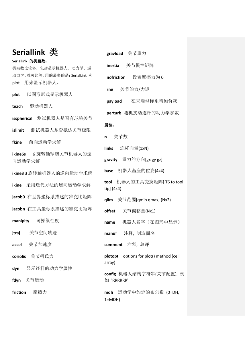
Seriallink 类
Seriallink 的类函数:
类函数比较多,包括显示机器人、动力学、逆
动力学、雅可比等,用的最多的是:SerialLink 和
plot 用来显示机器人。
plot 以图形形式显示机器人
teach 驱动机器人
isspherical 测试机器人是否有球腕关节
islimit 测试机器人是否抵达关节极限
fkine 前向运动学求解
ikine6s 6 旋转轴球腕关节机器人的逆
向运动学求解
ikine3 3 旋转轴机器人的逆向运动学求解
ikine 采用迭代方法的逆向运动学求解
gravload 关节重力
inertia 关节惯性矩阵
nofriction 设置摩擦力为 0
rne 关节的力/力矩
payload 在末端坐标系增加负载
perturb 随机扰动连杆的动力学参数
属性:
n 关节数
links 连杆向量(1xN)
gravity 重力的方向[gx gy gz]
base 机器人基座的位姿(4x4)
tool 机器人的工具变换矩阵[ T6 to tool
tip] (4x4)
jacob0 在世界坐标系描述的雅克比矩阵
qlim 关节范围[qmin qmax] (Nx2)
jacobn 在工具坐标系描述的雅克比矩阵
offset 关节偏移量(Nx1)
maniplty 可操纵性度
jtraj 关节空间轨迹
name 机器人名字(在图形中显示)
manuf 注释, 制造商名
accel 关节加速度
comment 注释, 总评
coriolis 关节柯氏力
dyn 显示连杆的动力学属性
fdyn 关节运动
friction 摩擦力
plotopt options for plot() method (cell
array)
config 机器人结构字符串(关节配置), 例
如 'RRRRRR'
mdh 运动学中约定的布尔数 (0=DH,
1=MDH)
�
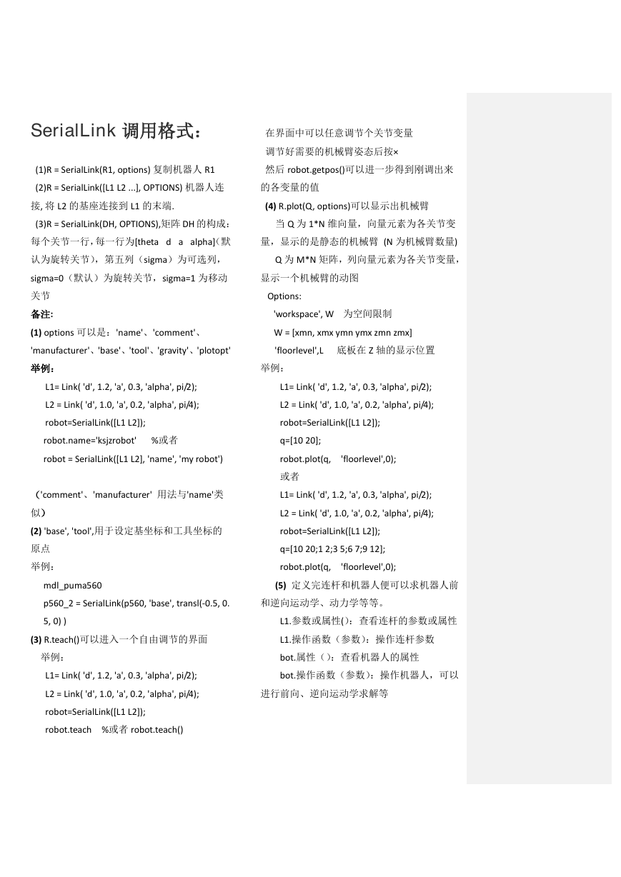
SerialLink 调用格式:
在界面中可以任意调节个关节变量
调节好需要的机械臂姿态后按×
(1)R = SerialLink(R1, options) 复制机器人 R1
然后 robot.getpos()可以进一步得到刚调出来
(2)R = SerialLink([L1 L2 ...], OPTIONS) 机器人连
的各变量的值
接, 将 L2 的基座连接到 L1 的末端.
(4) R.plot(Q, options)可以显示出机械臂
(3)R = SerialLink(DH, OPTIONS),矩阵 DH 的构成:
当 Q 为 1*N 维向量,向量元素为各关节变
每个关节一行,每一行为[theta d a alpha](默
量,显示的是静态的机械臂 (N 为机械臂数量)
认为旋转关节),第五列(sigma)为可选列,
Q 为 M*N 矩阵,列向量元素为各关节变量,
sigma=0(默认)为旋转关节,sigma=1 为移动
显示一个机械臂的动图
关节
备注:
Options:
'workspace', W 为空间限制
(1) options 可以是:'name'、'comment'、
W = [xmn, xmx ymn ymx zmn zmx]
'manufacturer'、'base'、'tool'、'gravity'、'plotopt'
'floorlevel',L 底板在 Z 轴的显示位置
举例:
举例:
L1= Link( 'd', 1.2, 'a', 0.3, 'alpha', pi/2);
L1= Link( 'd', 1.2, 'a', 0.3, 'alpha', pi/2);
L2 = Link( 'd', 1.0, 'a', 0.2, 'alpha', pi/4);
L2 = Link( 'd', 1.0, 'a', 0.2, 'alpha', pi/4);
robot=SerialLink([L1 L2]);
robot=SerialLink([L1 L2]);
robot.name='ksjzrobot' %或者
q=[10 20];
robot = SerialLink([L1 L2], 'name', 'my robot')
robot.plot(q, 'floorlevel',0);
或者
('comment'、'manufacturer' 用法与'name'类
L1= Link( 'd', 1.2, 'a', 0.3, 'alpha', pi/2);
似)
L2 = Link( 'd', 1.0, 'a', 0.2, 'alpha', pi/4);
(2) 'base', 'tool',用于设定基坐标和工具坐标的
robot=SerialLink([L1 L2]);
原点
举例:
q=[10 20;1 2;3 5;6 7;9 12];
robot.plot(q, 'floorlevel',0);
mdl_puma560
(5) 定义完连杆和机器人便可以求机器人前
p560_2 = SerialLink(p560, 'base', transl(-0.5, 0.
和逆向运动学、动力学等等。
5, 0) )
L1.参数或属性():查看连杆的参数或属性
(3) R.teach()可以进入一个自由调节的界面
L1.操作函数(参数):操作连杆参数
举例:
bot.属性():查看机器人的属性
L1= Link( 'd', 1.2, 'a', 0.3, 'alpha', pi/2);
bot.操作函数(参数):操作机器人,可以
L2 = Link( 'd', 1.0, 'a', 0.2, 'alpha', pi/4);
进行前向、逆向运动学求解等
robot=SerialLink([L1 L2]);
robot.teach %或者 robot.teach()
�
Matlab Robotic Toolbox V9.10 工具箱
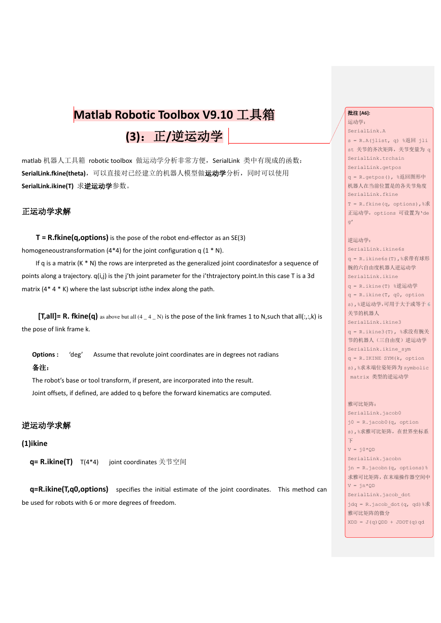
(3):正/逆运动学
matlab 机器人工具箱 robotic toolbox 做运动学分析非常方便,SerialLink 类中有现成的函数:
SerialLink.fkine(theta),可以直接对已经建立的机器人模型做运动学分析,同时可以使用
SerialLink.ikine(T) 求逆运动学参数。
正运动学求解
T = R.fkine(q,options) is the pose of the robot end-effector as an SE(3)
homogeneoustransformation (4*4) for the joint configuration q (1 * N).
If q is a matrix (K * N) the rows are interpreted as the generalized joint coordinatesfor a sequence of
批注 [A6]:
运动学:
SerialLink.A
s = R.A(jlist, q) %返回 jli
st 关节的齐次矩阵,关节变量为 q
SerialLink.trchain
SerialLink.getpos
q = R.getpos(), %返回图形中
机器人在当前位置是的各关节角度
SerialLink.fkine
T = R.fkine(q, options),%求
正运动学,options 可设置为‘de
g’
逆运动学:
SerialLink.ikine6s
q = R.ikine6s(T),%求带有球形
腕的六自由度机器人逆运动学
points along a trajectory. q(i,j) is the j’th joint parameter for the i’thtrajectory point.In this case T is a 3d
SerialLink.ikine
matrix (4* 4 * K) where the last subscript isthe index along the path.
[T,all]= R. fkine(q) as above but all (4 _ 4 _ N) is the pose of the link frames 1 to N,such that all(:,:,k) is
the pose of link frame k.
Options : ‘deg’ Assume that revolute joint coordinates are in degrees not radians
备注:
The robot’s base or tool transform, if present, are incorporated into the result.
Joint offsets, if defined, are added to q before the forward kinematics are computed.
逆运动学求解
(1)ikine
q= R.ikine(T) T(4*4) joint coordinates 关节空间
q=R.ikine(T,q0,options) specifies the initial estimate of the joint coordinates. This method can
be used for robots with 6 or more degrees of freedom.
q = R.ikine(T) %逆运动学
q = R.ikine(T, q0, option
s),%逆运动学,可用于大于或等于 6
关节的机器人
SerialLink.ikine3
q = R.ikine3(T), %求没有腕关
节的机器人(三自由度)逆运动学
SerialLink.ikine_sym
q = R.IKINE SYM(k, option
s),%求末端位姿矩阵为 symbolic
matrix 类型的逆运动学
雅可比矩阵:
SerialLink.jacob0
j0 = R.jacob0(q, option
s),%求雅可比矩阵,在世界坐标系
下
V = j0*QD
SerialLink.jacobn
jn = R.jacobn(q, options)%
求雅可比矩阵,在末端操作器空间中
V = jn*QD
SerialLink.jacob_dot
jdq = R.jacob_dot(q, qd)%求
雅可比矩阵的微分
XDD = J(q)QDD + JDOT(q)qd
�





 2023年江西萍乡中考道德与法治真题及答案.doc
 2012年重庆南川中考生物真题及答案.doc
 2013年江西师范大学地理学综合及文艺理论基础考研真题.doc
 2020年四川甘孜小升初语文真题及答案I卷.doc
 2020年注册岩土工程师专业基础考试真题及答案.doc
 2023-2024学年福建省厦门市九年级上学期数学月考试题及答案.doc
 2021-2022学年辽宁省沈阳市大东区九年级上学期语文期末试题及答案.doc
 2022-2023学年北京东城区初三第一学期物理期末试卷及答案.doc
 2018上半年江西教师资格初中地理学科知识与教学能力真题及答案.doc
 2012年河北国家公务员申论考试真题及答案-省级.doc
 2020-2021学年江苏省扬州市江都区邵樊片九年级上学期数学第一次质量检测试题及答案.doc
 2022下半年黑龙江教师资格证中学综合素质真题及答案.doc