logo资料库

TI最新官方电机驱动资料.pdf

第1页 / 共574页
第2页 / 共574页
第3页 / 共574页
第4页 / 共574页
第5页 / 共574页
第6页 / 共574页
第7页 / 共574页
第8页 / 共574页
资料共574页,剩余部分请下载后查看
Table of Contents
1 Introduction
1.1 An Overview of InstaSPIN-FOC and FAST
1.1.1 FAST Estimator Features
1.1.2 InstaSPIN-FOC Solution Features
1.1.3 InstaSPIN-FOC Block Diagrams
1.1.4 Comparing FAST Estimator to Typical Solutions
1.1.5 FAST Provides Sensorless FOC Performance
1.1.5.1 FAST Estimator Replaces Mechanical Sensor
1.1.5.2 Rotor Angle Accuracy Critical for Performance
1.2 An Overview of InstaSPIN-MOTION and SpinTAC
1.2.1 InstaSPIN-MOTION Key Capabilities and Benefits
1.2.1.1 The FAST Unified Software Observer
1.2.1.2 The SpinTAC Motion Control Suite
1.2.1.2.1 IDENTIFY
1.2.1.2.2 CONTROL
1.2.1.2.3 MOVE
1.2.1.2.4 PLAN
1.2.1.3 Additional InstaSPIN-MOTION Features
1.2.2 InstaSPIN-MOTION Block Diagrams
1.2.3 Application Examples
1.2.3.1 Treadmill Conveyor: Smooth Motion Across Varying Speeds and Loads
1.2.3.2 Video Camera: Smooth Motion and Position Accuracy at Low Speeds
1.2.3.3 Washing Machine: Smooth Motion and Position Accuracy at Low Speeds
1.2.3.3.1 Agitation Cycle
1.2.3.3.2 Spin Cycles
1.2.3.3.3 InstaSPIN-MOTION Works Over the Entire Operating Range
2 Quick Start Kits - TI Provided Software and Hardware
2.1 Evaluating InstaSPIN-FOC and InstaSPIN-MOTION
3 InstaSPIN and MotorWare
3.1 MotorWare Directory Structure
3.1.1 MotorWare – drivers
3.1.2 MotorWare – ide
3.1.3 MotorWare – modules
3.1.4 MotorWare – solutions
3.2 MotorWare Object-Oriented Design
3.2.1 Objects
3.2.2 Methods
3.2.2.1 Init method
3.2.2.2 Set method
3.2.2.3 Get method
3.2.2.4 Run method
3.3 InstaSPIN-FOC API
3.3.1 Controller API Functions – ctrl.c, ctrl.h, CTRL_obj.h
3.3.1.1 CTRL Enumerations and Structures
3.3.1.2 CTRL State Control and Error Handling
3.3.1.3 CTRL Get Functions
3.3.1.4 CTRL Counter Functions
3.3.1.5 CTRL Set Functions
3.3.1.6 CTRL Run and Compute Functions
3.3.2 Estimator API Functions – FAST Library – est.h, est_states.h
3.3.2.1 EST Enumerations and Structures
3.3.2.2 EST Set Functions
3.3.2.3 EST Get Functions
3.3.2.4 EST Run and Compute Functions
3.3.2.5 EST Counter Functions
3.3.2.6 EST State Control and Error Handling Functions
3.3.3 Hardware Abstraction Layer (HAL) API Functions – hal.c, hal.h, hal_obj.h
3.3.3.1 HAL Enumerations and Structures
3.3.3.2 HAL – ADC and AFE
3.3.3.3 HAL – PWM and PWM-DAC
3.3.3.4 HAL – CPU Timers
3.3.3.5 HAL – GPIO and LED
3.3.3.6 HAL – Miscellaneous
3.3.4 User Settings – user.c, user.h, userParams.h
3.3.4.1 USER Enumerations and Structures
3.3.4.2 USER Set and Compute Functions
3.3.4.3 USER Error Handling Functions
3.3.5 Miscellaneous Functions
3.4 InstaSPIN-MOTION and the SpinTAC API
3.4.1 Header Files, Public Library, and ROM Library
3.4.2 Version Information
3.4.2.1 Code Example for returning SpinTAC Version Information
3.4.2.1.1 Include the Header File
3.4.2.1.2 Declare the Global Structure
3.4.2.1.3 Initialize the Configuration Variables
3.4.2.1.4 Return the Version Information
3.4.3 SpinTAC Structure Names
3.4.4 SpinTAC Variables
3.5 SpinTAC API
3.5.1 SpinTAC Velocity Control
3.5.1.1 SpinTAC Velocity Control Interface
3.5.1.2 SpinTAC Velocity Control Run Function
3.5.2 SpinTAC Velocity Move
3.5.2.1 SpinTAC Velocity Move Interface
3.5.2.2 SpinTAC Velocity Move Run Function
3.5.3 SpinTAC Velocity Plan
3.5.3.1 SpinTAC Velocity Plan Interface
3.5.3.2 SpinTAC Velocity Plan Primary Functions
3.5.4 SpinTAC Velocity Identify
3.5.4.1 SpinTAC Velocity Identify Interface
3.5.4.2 SpinTAC Velocity Identify Run Function
3.5.5 SpinTAC Position Convert
3.5.5.1 SpinTAC Position Convert Interfaces
3.5.5.2 SpinTAC Position Convert Run Function
3.5.6 SpinTAC Position Control
3.5.6.1 SpinTAC Position Control Interface
3.5.6.2 SpinTAC Position Control Run Function
3.5.7 SpinTAC Position Move
3.5.7.1 Position Move Interface
3.5.7.2 SpinTAC Position Move Run Function
3.5.8 SpinTAC Position Plan
3.5.8.1 Position Plan Interface
3.5.8.2 SpinTAC Position Plan Primary Functions
3.5.9 SpinTAC Functions
4 User Parameters (user.h)
4.1 Currents and Voltages
4.1.1 USER_IQ_FULL_SCALE_FREQ_Hz
4.1.2 USER_IQ_FULL_SCALE_VOLTAGE_V
4.1.3 USER_ADC_FULL_SCALE_VOLTAGE_V
4.1.4 USER_VOLTAGE_SF
4.1.5 USER_IQ_FULL_SCALE_CURRENT_A
4.1.6 USER_ADC_FULL_SCALE_CURRENT_A
4.1.7 USER_CURRENT_SF
4.1.8 USER_NUM_CURRENT_SENSORS
4.1.9 USER_NUM_VOLTAGE_SENSORS
4.1.10 I_A_offset , I_B_offset , I_C_offset
4.1.11 V_A_offset , V_B_offset , V_C_offset
4.2 Clocks and Timers
4.2.1 USER_SYSTEM_FREQ_MHz
4.2.2 USER_PWM_FREQ_kHz
4.2.3 USER_MAX_VS_MAG_PU
4.2.4 USER_PWM_PERIOD_usec
4.2.5 USER_ISR_FREQ_Hz
4.2.6 USER_ISR_PERIOD_usec
4.3 Decimation
4.3.1 USER_NUM_PWM_TICKS_PER_ISR_TICK
4.3.2 USER_NUM_ISR_TICKS_PER_CTRL_TICK
4.3.3 USER_NUM_CTRL_TICKS_PER_CURRENT_TICK
4.3.4 USER_NUM_CTRL_TICKS_PER_EST_TICK
4.3.5 USER_NUM_CTRL_TICKS_PER_SPEED_TICK
4.3.6 USER_NUM_CTRL_TICKS_PER_TRAJ_TICK
4.3.7 USER_CTRL_FREQ_Hz
4.3.8 USER_EST_FREQ_Hz
4.3.9 USER_TRAJ_FREQ_Hz
4.3.10 USER_CTRL_PERIOD_usec
4.3.11 USER_CTRL_PERIOD_sec
4.4 Limits
4.4.1 USER_MAX_NEGATIVE_ID_REF_CURRENT_A
4.4.2 USER_ZEROSPEEDLIMIT
4.4.3 USER_FORCE_ANGLE_FREQ_Hz
4.4.4 USER_MAX_CURRENT_SLOPE_POWERWARP
4.4.5 USER_MAX_ACCEL_Hzps
4.4.6 USER_MAX_ACCEL_EST_Hzps
4.4.7 USER_MAX_CURRENT_SLOPE
4.4.8 USER_IDRATED_FRACTION_FOR_RATED_FLUX
4.4.9 USER_IDRATED_FRACTION_FOR_L_IDENT
4.4.10 USER_IDRATED_DELTA
4.4.11 USER_SPEEDMAX_FRACTION_FOR_L_IDENT
4.4.12 USER_FLUX_FRACTION
4.4.13 USER_POWERWARP_GAIN
4.4.14 USER_R_OVER_L_EST_FREQ_Hz
4.5 Poles
4.5.1 USER_VOLTAGE_FILTER_POLE_Hz
4.5.2 USER_VOLTAGE_FILTER_POLE_rps
4.5.3 USER_OFFSET_POLE_rps
4.5.4 USER_FLUX_POLE_rps
4.5.5 USER_DIRECTION_POLE_rps
4.5.6 USER_SPEED_POLE_rps
4.5.7 USER_DCBUS_POLE_rps
4.5.8 USER_EST_KAPPAQ
4.6 User Motor and ID Settings
4.6.1 USER_MOTOR_TYPE
4.6.2 USER_MOTOR_NUM_POLE_PAIRS
4.6.3 USER_MOTOR_Rr
4.6.4 USER_MOTOR_Rs
4.6.5 USER_MOTOR_Ls_d
4.6.6 USER_MOTOR_Ls_q
4.6.7 USER_MOTOR_RATED_FLUX
4.6.8 USER_VOLTAGE_FILTER_POLE_Hz
4.6.9 USER_MOTOR_RES_EST_CURRENT
4.6.10 USER_MOTOR_IND_EST_CURRENT
4.6.11 USER_MOTOR_MAX_CURRENT
4.6.12 USER_MOTOR_FLUX_EST_FREQ_Hz
4.6.13 USER_MOTOR_ENCODER_LINES (InstaSPIN-MOTION Only)
4.6.14 USER_MOTOR_MAX_SPEED_KRPM (InstaSPIN-MOTION Only)
4.6.15 USER_SYSTEM_INERTIA (InstaSPIN-MOTION Only)
4.6.16 USER_SYSTEM_FRICTION (InstaSPIN-MOTION Only)
4.6.17 USER_SYSTEM_BANDWIDTH_SCALE (InstaSPIN-MOTION Only)
4.7 SpinTAC Parameters (spintac_velocity.h and spintac_position.h)
4.7.1 Macro Definitions
4.7.1.1 ST_MREV_ROLLOVER (spintac_position.h only)
4.7.1.2 ST_EREV_MAXIMUM (spintac_position.h only)
4.7.1.3 ST_POS_ERROR_MAXIMUM_MREV (spintac_position.h only)
4.7.1.4 ST_ISR_TICKS_PER_SPINTAC_TICK
4.7.1.5 ST_SPEED_SAMPLE_TIME
4.7.1.6 ST_SPEED_PU_PER_KRPM
4.7.1.7 ST_SPEED_KRPM_PER_PU
4.7.1.8 ST_MOTOR_INERTIA_PU
4.7.1.9 ST_MOTOR_FRICTION_PU
4.7.1.10 ST_MIN_ID_SPEED_RPM
4.7.1.11 ST_MIN_ID_SPEED_PU
4.7.1.12 ST_ID_INCOMPLETE_ERROR
4.7.1.13 ST_VARS_DEFAULTS
4.7.2 Type Definitions
4.7.2.1 VEL_Params_t / POS_Params_t
4.7.2.2 ST_Obj
4.7.2.3 ST_Handle
4.7.2.4 ST_PlanButton_e
4.7.2.5 ST_Vars_t
4.7.3 Functions
4.7.3.1 ST_init
4.7.3.2 ST_setupPosConv
4.7.3.3 ST_setupVelCtl (Velocity Control Only)
4.7.3.4 ST_setupPosCtl (Position Control Only)
4.7.3.5 ST_setupVelMove (Velocity Control Only)
4.7.3.6 ST_setupPosMove (Position Control Only)
4.7.3.7 ST_setupVelPlan (Velocity Control Only)
4.7.3.8 ST_setupPosPlan (Position Control Only)
4.7.3.9 ST_setupVelId (Velocity Control Only)
4.7.3.10 ST_runPosConv
4.7.3.11 ST_runVelCtl (Velocity Control Only)
4.7.3.12 ST_runPosCtl (Position Control Only)
4.7.3.13 ST_runVelMove (Velocity Control Only)
4.7.3.14 ST_runPosMove (Position Control Only)
4.7.3.15 ST_runVelPlan (Velocity Control Only)
4.7.3.16 ST_runVelPlanTick (Velocity Control Only)
4.7.3.17 ST_runPosPlan (Position Control Only)
4.7.3.18 ST_runPosPlanTick (Position Control Only)
4.7.3.19 ST_runVelId (Velocity Control Only)
4.8 Setting ACIM Motor Parameters in user.h
4.8.1 Getting Parameters From an ACIM Datasheet
4.8.1.1 Number of Pole Pairs
4.8.1.2 Entering ACIM Motor Parameters From a Datasheet to user.h
4.8.1.3 Getting the Rated Magnetizing Current of an ACIM
4.8.1.4 Getting the Rated Flux of an ACIM
5 Managing Motor Signals
5.1 Software Prerequisites
5.1.1 IQ Full-Scale Frequency
5.1.2 IQ Full-Scale Voltage
5.1.3 IQ Full-Scale Current
5.1.4 Max Current
5.1.5 Decimation Rates
5.1.6 System Frequency
5.1.7 PWM Frequency
5.1.8 Max Voltage Vector
5.2 Hardware Prerequisites
5.2.1 Current Feedback Gain
5.2.2 Current Feedback Polarity
5.2.2.1 Positive Feedback
5.2.2.2 Negative Feedback
5.2.3 Voltage Feedback
5.2.4 Voltage Filter Pole
5.2.5 Number of Shunt Resistors
5.2.6 Deadtime Configuration
5.2.7 Analog Inputs Configuration
5.2.8 PWM Outputs Configuration
6 Motor Identification and State Diagrams
6.1 InstaSPIN Motor Identification
6.2 Motor Identification Process Overview
6.2.1 Controller (CTRL) State Machine
6.2.2 Estimator (EST) State Machine
6.2.3 Controller (CTRL) and Estimator (EST) State Machine Dependencies
6.3 Differences between PMSM and ACIM Identification Process
6.4 Prerequisites
6.4.1 Mechanical Prerequisites
6.4.1.1 Motor Connection
6.4.1.2 Order of the Phases
6.4.1.3 Minimum Mechanical Load
6.4.2 Hardware Prerequisites
6.4.3 Software Prerequisites
6.4.4 Software Configuration for PMSM Motor Identification
6.4.4.1 Motor Type
6.4.4.2 Number of Pole Pairs
6.4.4.3 Frequency for Rhf and Lhf
6.4.4.4 Current for Rs
6.4.4.5 Current for Ls
6.4.4.6 Frequency for Ls and Flux
6.4.5 Software Configuration for ACIM Motor Identification
6.4.5.1 Motor Type
6.4.5.2 Number of Pole Pairs
6.4.5.3 Frequency for Rhf and Lhf
6.4.5.4 Rated Flux
6.4.5.5 Current for Rs
6.4.5.6 Frequency for IdRated, Ls and Rr
6.5 Full Identification of PMSM Motors
6.5.1 CTRL_State_Idle and EST_State_Idle
6.5.2 CTRL_State_OffLine and EST_State_Idle (Hardware Offsets Calibrated)
6.5.3 CTRL_State_OnLine and EST_State_RoverL
6.5.3.1 Amplitude of Injected Current for RoverL
6.5.3.2 Frequency of Injected Current for RoverL
6.5.3.3 Measurement Time for RoverL
6.5.3.4 Troubleshooting Current Controller Stability During RoverL Identification
6.5.3.5 Adjusting Resulting Current Controller Gains for High-Speeds
6.5.4 CTRL_State_OnLine and EST_State_Rs
6.5.4.1 Troubleshooting Current Controller Stability During Rs Identification
6.5.5 CTRL_State_OnLine and EST_State_RampUp
6.5.5.1 Ramp-Up Current Amplitude
6.5.5.1.1 Troubleshooting Motor Shaft Stopping During Ramp-Up
6.5.5.2 Ramp-Up Time and Acceleration
6.5.5.2.1 Troubleshooting Motor Shaft for Smoother Ramp
6.5.5.3 Ramp-Up Final Speed for PMSM
6.5.6 CTRL_State_OnLine and EST_State_RatedFlux
6.5.6.1 Current Ramp-Down
6.5.6.2 Total Measurement Time
6.5.6.3 Troubleshooting Flux Measurement
6.5.7 CTRL_State_OnLine and EST_State_Ls
6.5.7.1 Ramp-Up Current
6.5.7.2 Troubleshooting Ls Identification
6.5.7.3 Ls_d and Ls_q, Direct and Quadrature Stator Inductance
6.5.8 CTRL_State_OnLine and EST_State_RampDown
6.5.9 CTRL_State_OnLine and EST_State_MotorIdentified
6.5.10 CTRL_State_Idle and EST_State_Idle
6.6 Full Identification of ACIM Motors
6.6.1 CTRL_State_Idle and EST_State_Idle
6.6.2 CTRL_State_OffLine and EST_State_Idle
6.6.3 CTRL_State_OnLine and EST_State_RoverL
6.6.4 CTRL_State_OnLine and EST_State_Rs
6.6.5 CTRL_State_OnLine and EST_State_RampUp
6.6.5.1 Ramp-Up Final Speed for ACIM
6.6.6 CTRL_State_OnLine and EST_State_IdRated
6.6.6.1 Reducing Oscillation to Improve Id Rated Measurement
6.6.6.2 Reading Id Rated Final Value
6.6.7 CTRL_State_OnLine and EST_State_RatedFlux
6.6.7.1 Troubleshooting Flux Measurement
6.6.8 CTRL_State_OnLine and EST_State_RampDown
6.6.9 CTRL_State_Idle and EST_State_LockRotor
6.6.9.1 Troubleshooting Locked Rotor Test
6.6.10 CTRL_State_OnLine and EST_State_Ls
6.6.11 CTRL_State_OnLine and EST_State_Rr
6.6.12 CTRL_State_OnLine and EST_State_RampDown
6.6.13 CTRL_State_OnLine and EST_State_MotorIdentified
6.6.14 CTRL_State_Idle and EST_State_Idle
6.7 Recalibration of PMSM and ACIM Motor Identification
6.7.1 Recalibration of PMSM and ACIM Motors After Full Identification
6.7.1.1 Start-Up Time Consideration
6.7.1.2 CTRL_State_Idle and EST_State_Idle
6.7.1.3 CTRL_State_OffLine and EST_State_Idle
6.7.1.4 CTRL_State_OnLine and EST_State_Rs
6.7.1.4.1 Managing Time Required for Rs Recalibration
6.7.1.4.2 Software configuration for Rs recalibration
6.7.1.5 CTRL_State_OnLine and EST_State_OnLine
6.7.1.5.1 Transitioning to Online State from CTRL Online and EST Rs
6.7.1.5.2 Transitioning to Online state from (CTRL Idle or CTRL Offline) and EST Idle
6.7.1.6 CTRL_State_Idle and EST_State_Idle
6.7.2 Recalibration of PMSM and ACIM Motors after Using Parameters from user.h
6.8 Setting PMSM Motor Parameters in user.h
6.8.1 Getting Parameters from a PMSM Datasheet
6.8.1.1 Number of Pole Pairs
6.8.1.2 Stator Resistance (Rs)
6.8.1.3 Stator Inductance (Ls_d and Ls_q)
6.8.1.4 Rated Flux (ψ)
6.9 Troubleshooting Motor Identification
6.9.1 General Checklist
6.9.2 Troubleshooting PMSM Motor Identification
6.9.2.1 Identifying PMSM Motors When Load Cannot be Detached
6.9.2.2 Can Motor Rotate with the Attached Load?
6.9.2.3 Run First Three Steps of Identification
6.9.2.4 Run Using Motor Parameters from user.h
6.9.2.5 Troubleshooting Current Controller Stability during RoverL Identification
6.9.2.6 Troubleshooting Motor Shaft Stopping During Ramp-Up
6.9.2.7 Troubleshooting Motor Shaft for Smoother Ramp
6.9.2.8 Troubleshooting Flux Measurement
6.9.2.9 Troubleshooting Ls Identification
6.9.2.9.1 Identifying Low Inductance PMSM Motors
6.9.2.9.2 Identifying Inductance of Salient PMSM Motors
6.9.2.9.3 Identifying Inductance of Salient PMSM Motors
6.9.2.10 Identifying High-Speed PMSM Motors
6.9.2.11 Identifying High-Cogging Torque PMSM Motors
6.9.3 Troubleshooting ACIM Motor Identification
6.9.3.1 Identifying Low-Voltage and High-Current ACIM Motors
6.9.3.2 Identifying Low-Inductance ACIM Motors
6.9.3.3 Troubleshooting Flux Measurement
6.9.3.4 Troubleshooting Locked Rotor Test
7 Inertia Identification
7.1 InstaSPIN-MOTION Inertia Identification
7.2 Inertia Identification Process Overview
7.3 Software Configuration for SpinTAC Velocity Identify
7.3.1 Include the Header File
7.3.2 Declare the Global Variables
7.3.3 Initialize the Configuration Variables
7.3.4 Call SpinTAC Velocity Identify
7.4 Troubleshooting Inertia Identification
7.4.1 ERR_ID
7.4.2 2003 Error
7.4.3 2004 Error
7.4.3.1 Motor Spins Continuously
7.4.3.2 Motor Does Not Spin Initially
7.4.4 2006 Error
7.5 Difficult Applications for Inertia Identification
7.5.1 Automotive Pumps (Large-Cogging Force / Large Friction)
7.5.2 Direct Drive Washing Machines (Low-Rated Speed and Large Back EMF)
7.5.3 Compressors (Large Start-Up Current)
8 MCU Considerations
8.1 InstaSPIN-Enabled Devices
8.1.1 softwareUpdate1p6() - Function is Required in User Code
8.2 ROM and User Memory Overview
8.2.1 InstaSPIN-FOC Full Implementation in ROM
8.2.1.1 Executing from ROM and RAM
8.2.1.2 Executing from ROM and FLASH
8.2.2 InstaSPIN-FOC Minimum Implementation in ROM
8.2.2.1 Executing from ROM and RAM
8.2.2.2 Executing from ROM and FLASH
8.2.3 InstaSPIN-MOTION in ROM
8.2.3.1 Executing InstaSPIN-MOTION in the Main Interrupt
8.2.3.2 Executing Library from RAM
8.2.3.3 Executing Library from Flash
8.3 Details on CPU Load and Memory Footprint Measurements
8.3.1 CPU Utilization Measurement Details
8.3.2 Memory Allocation Measurement Details
8.3.3 IQ Math Built in ROM
8.3.4 Stack Utilization Measurement Details
8.3.5 InstaSPIN Main Interrupt
8.3.6 Clock Rate
8.4 Memory Footprint
8.4.1 Device Memory Map
8.4.1.1 F2806xF and F2806xM Devices
8.4.1.2 F2805xF and F2805xM Devices
8.4.1.3 F2802xF Devices
8.4.2 InstaSPIN Memory Footprint
8.4.2.1 F2806xF and F2805xF Devices
8.4.2.2 F2802xF Devices
8.4.2.3 F2806xM and F2805xM Devices
8.4.3 Memory Wait-States
8.4.3.1 F2806xF/M Devices
8.4.3.2 F2805xF/M Devices
8.4.3.3 F2802xF Devices
8.4.4 Flash Configuration Required Even for RAM-Only Execution
8.4.5 Debug (IDE) of EXE-Only Memory
8.5 CPU Load
8.5.1 F2806xF Devices
8.5.1.1 CPU Cycles
8.5.1.1.1 User Code in RAM
8.5.1.1.2 User Code in FLASH
8.5.1.2 CPU Load with PWM = 10 kHz
8.5.1.3 CPU Load with PWM = 20 kHz
8.5.1.4 CPU Load Examples
8.5.1.4.1 Example 1
8.5.1.4.2 Example 2
8.5.2 F2806xM Devices
8.5.2.1 CPU Cycles
8.5.2.1.1 RAM Execution - SpinTAC Library and User Code
8.5.2.1.2 FLASH Execution - SpinTAC Library and User Code
8.5.2.2 CPU Load Examples
8.5.2.2.1 Example 1
8.5.2.2.2 Example 2
8.5.2.2.3 Example 3
8.5.2.2.4 Example 4 (SpinTAC Position)
8.5.3 F805xF Devices
8.5.3.1 CPU Cycles
8.5.3.2 CPU Load with PWM = 10 kHz
8.5.3.3 CPU Load with PWM = 20 kHz
8.5.4 F2805xM Devices
8.5.4.1 CPU Cycles
8.5.4.1.1 FLASH Execution - SpinTAC Library and User Code
8.5.5 F2802xF Devices
8.5.5.1 CPU Cycles
8.5.5.2 CPU Load with PWM = 10 kHz
8.5.5.3 CPU Load with PWM = 20 kHz
8.6 Digital and Analog Pins
8.6.1 Pin Utilization
8.6.2 F2805x Analog Front-End (AFE)
8.6.2.1 Consideration of AFE Module
8.6.2.2 Routing Current Signals
8.6.2.3 Voltage Reference Connection
8.6.2.4 Routing Voltage Signals
9 Real-Time Structure
9.1 InstaSPIN Software Execution Clock Tree
9.2 Decimating in Software for Real-Time Scheduling
9.2.1 USER_NUM_ISR_TICKS_PER_CTRL_TICK
9.2.2 USER_NUM_CTRL_TICKS_PER_CURRENT_TICK
9.2.3 USER_NUM_CTRL_TICKS_PER_EST_TICK
9.2.4 Practical Example
9.2.5 USER_NUM_CTRL_TICKS_PER_SPEED_TICK
9.2.6 USER_NUM_CTRL_TICKS_PER_TRAJ_TICK
9.3 Decimating in Hardware
10 Managing Startup Time
10.1 Startup with Offsets and Rs Recalibration
10.2 Startup with Only Offsets Recalibration
10.3 Startup with Rs Recalibration
10.4 Startup with No Recalibration
10.5 Bypassing Inertia Estimation
11 Tuning Regulators
11.1 PI Controllers Introduction
11.2 PI Design for Current Controllers
11.3 PI Design for Speed Controllers
11.4 Calculating PI Gains Based On Stability and Bandwidth
11.5 Calculating Speed and Current PI Gains Based on Damping Factor
11.6 Considerations When Adding Poles to the Speed Loop
11.7 Speed PI Controller Considerations: Current Limits, Clamping and Inertia
11.8 Considerations When Designing PI Controllers for FOC Systems
11.8.1 FOC Differences Between Motor Types
11.8.2 Coupling Between Q-Axis and D-Axis
11.9 Sampling and Digital Systems Considerations
11.9.1 Sampling Period Considerations in the Integral Gain
11.9.2 Number Format Considerations
11.9.3 PI Coefficients Scaling Considerations
12 InstaSPIN-MOTION Controllers
12.1 Stability
12.1.1 Quantifying Stability
12.1.1.1 SpinTAC Velocity Control Stability
12.1.1.2 SpinTAC Position Control Stability
12.1.2 Performance
12.1.2.1 Frequency Domain Analysis
12.1.2.2 Time Domain Analysis
12.1.3 Trade-Off Between Stability and Performance
12.1.4 Tuning the SpinTAC Controller
12.1.4.1 Considerations
12.1.4.2 Tuning the InstaSPIN-MOTION Controller
12.2 Software Configuration for the SpinTAC Velocity Control
12.2.1 Include the Header File
12.2.2 Declare the Global Structure
12.2.3 Initialize the Configuration Variables
12.2.4 Call SpinTAC Velocity Control
12.2.5 Troubleshooting SpinTAC Velocity Control
12.2.5.1 ERR_ID
12.3 Optimal Performance in Speed Control
12.3.1 Introduction
12.3.2 Comparing Speed Controllers
12.3.3 Disturbance Rejection
12.3.4 Profile Tracking
12.3.5 InstaSPIN-MOTION Velocity Control Advantage
12.3.5.1 Single Parameter Tuning
12.3.5.2 Disturbance Rejection Test
12.3.5.3 Feedforward
12.3.5.4 No Integrator Windup
12.3.5.5 Minimum Startup Overshoot
12.3.5.6 Conclusions
12.4 Software Configuration for SpinTAC Position Control
12.4.1 Include the Header File
12.4.2 Declare the Global Structure
12.4.3 Initialize the Configuration Variables
12.4.4 Call SpinTAC Position Control
12.4.5 Troubleshooting SpinTAC Position Control
12.4.5.1 ERR_ID
12.5 Optimal Performance in Position Control
12.5.1 Introduction
12.5.2 Comparing Position Controllers
12.5.3 Disturbance Rejection
12.5.4 Profile Tracking
12.5.5 InstaSPIN-MOTION Position Control Advantage
12.5.5.1 Single Parameter Tuning
12.5.5.2 Disturbance Rejection
12.5.5.3 Feedforward
12.5.5.4 Low-Speed Operation and Smooth Startup
12.5.5.5 Minimum Step Response Settling Time
12.5.5.6 Conclusions
13 Trajectory Planning
13.1 InstaSPIN-MOTION Profile Generation
13.1.1 Jerk Impact on System Performance
13.2 Software Configuration for SpinTAC Velocity Move
13.2.1 Include the Header File
13.2.2 Declare the Global Structure
13.2.3 Initialize the Configuration Variables
13.2.4 Call SpinTAC Velocity Move
13.2.5 Troubleshooting SpinTAC Velocity Move
13.2.5.1 ERR_ID
13.3 Software Configuration for SpinTAC Position Move
13.3.1 Include the Header File
13.3.2 Declare the Global Structure
13.3.3 Initialize the Configuration Variables
13.3.4 Call SpinTAC Position Move
13.3.5 Troubleshooting SpinTAC Position Move
13.3.5.1 Position Profile Limits
13.3.5.2 ERR_ID
13.4 InstaSPIN-MOTION Sequence Planning
13.4.1 SpinTAC Velocity Plan Elements
13.4.1.1 States
13.4.1.2 Transitions
13.4.1.3 Conditions
13.4.1.4 Variables
13.4.1.5 Actions
13.4.2 SpinTAC Velocity Plan Element Limits
13.4.2.1 Example of Sizing SpinTAC Velocity Plan Configuration Array
13.4.3  SpinTAC Velocity Plan Example: Washing Machine Agitation
13.4.4 SpinTAC Velocity Plan Example: Garage Door
13.4.5 SpinTAC Velocity Plan Example: Washing Machine
13.4.6 SpinTAC Position Plan Example: Vending Machine
13.5 Software Configuration for SpinTAC Velocity Plan
13.5.1 Include the Header File
13.5.2 Define the Size of the Configuration Array
13.5.3 Declare the Global Structure
13.5.4 Initialize the Configuration Variables
13.5.5 Call SpinTAC Velocity Plan
13.5.6 Call SpinTAC Velocity Plan Tick
13.5.7 Update SpinTAC Velocity Plan with SpinTAC Velocity Move Status
13.6 Troubleshooting SpinTAC Velocity Plan
13.6.1 ERR_ID
13.6.2 Configuration Errors
13.7 Software Configuration for SpinTAC Position Plan
13.7.1 Include the Header File
13.7.2 Define the Size of the Configuration Array
13.7.3 Declare the Global Structure
13.7.4 Initialize the Configuration Variables
13.7.5 Call SpinTAC Position Plan
13.7.6 Call SpinTAC Position Plan Tick
13.7.7 Update SpinTAC Position Plan with SpinTAC Position Move Status
13.8 Troubleshooting SpinTAC Position Plan
13.8.1 ERR_ID
13.8.2 Configuration Errors
13.9 Conclusion
14 Managing Full Load at Startup, Low-Speed and Speed Reversal
14.1 Low-Speed Operation with Full Load
14.1.1 Low Speed with Full Load Considerations
14.1.1.1 Enable Offsets Recalibration
14.1.1.2 Enable Stator Rs Recalibration
14.1.1.3 Disable Forced Angle
14.1.1.4 Tune Speed Controller to Avoid Motor Stall
14.1.1.5 Tune Voltage Feedback Circuit
14.1.2 Low Speed With Full Load Transient Examples
14.1.2.1 4-Hz, No-Load to Full-Load Transient
14.1.2.2 2-Hz, No-Load to Full-Load Transient
14.2 Speed Reversal with Full Load
14.2.1 Low Speed with Full Load Speed Reversal Considerations
14.2.2 Low Speed with Full Load Speed Reversal Examples
14.2.2.1 From -4 to +4 Hz with Full Load
14.2.2.2 From -2 to +2 Hz with Full Load
14.3 Motor Startup with Full Load
14.3.1 Motor Startup with Full Load Considerations
14.3.1.1 Enable Forced Angle
14.3.2 Motor Startup with Full Load Examples
14.3.2.1 From Standstill to 4 Hz with Full Load
14.3.2.2 From Standstill to 2 Hz with Full Load
14.4 Rapid Acceleration from Standstill With Full Load
14.4.1 Fastest Motor Startup with Full Load without Motor Alignment Considerations
14.4.1.1 Load Valid Offsets and Disable Offset Recalibration
14.4.1.2 Load Valid Rs and Disable Rs Recalibration
14.4.1.3 Fastest Motor Startup with Full Load without Motor Alignment Example
14.4.2 Fastest Motor Startup with Full Load with Motor Alignment Considerations
14.4.2.1 Maximize Current Slope
14.4.2.2 Fastest Motor Startup with Full Load with Motor Alignment Example
14.5 Overloading and Motor Overheating
14.5.1 Overloading and Motor Overheating Considerations
14.5.2 Overloading and Motor Overheating Example
14.6 InstaSPIN-MOTION and Low-Speed Considerations
15 Rs Online Recalibration
15.1 Overview
15.2 Resistance vs. Temperature
15.3 Accurate Rs Knowledge Needed at Low Speeds Including Startup
15.4 Introduction to Rs Online Recalibration
16 PowerWarp™
16.1 Overview
16.2 Enabling PowerWarp
16.3 PowerWarp Current Slopes
16.4 Practical Example
16.5 Case Study
17 Shunt Current Measurements
17.1 Introduction
17.2 Signals
17.3 1-Shunt
17.4 2-Shunt
17.5 3-Shunt
17.6 Development Kits
17.6.1 DRV8312
17.6.2 DRV8301
17.7 Conclusion
18 Sensored Systems
18.1 Hardware Configuration for Quadrature Encoder
18.1.1 Pin Usage
18.2 Software Configuration for Quadrature Encoder
18.2.1 Configure Motor for EQEP Operation
18.2.2 Initialize EQEP Handle
18.2.3 Set Digital IO to connect to QEP Peripheral
18.2.4 Enable Clock to eQEP
18.2.5 Initialize ENC Module
18.2.6 Set Up ENC Module
18.2.7 Call eQEP Function
18.2.8 Provide eQEP Angle to FOC
18.3 InstaSPIN-MOTION Position Convert
18.3.1 Software Configuration for SpinTAC Position Convert
18.3.1.1 Include the Header File
18.3.1.2 Declare the Global Structure
18.3.1.3 Initialize the Configuration Variables
18.3.1.4 Call SpinTAC Position Convert
18.3.2 Troubleshooting SpinTAC Position Convert
18.3.2.1 ERR_ID
19 Difficult Motors
20 Adding System Functions
21 Building Your InstaSPIN-FOC and InstaSPIN-MOTION Board
A Definition of Terms and Acronyms
Revision History (E to F)
Revision History (D to E)
Important Notice
InstaSPIN-FOC™ and InstaSPIN-MOTION™ User's Guide Literature Number: SPRUHJ1F January 2013–Revised July 2014
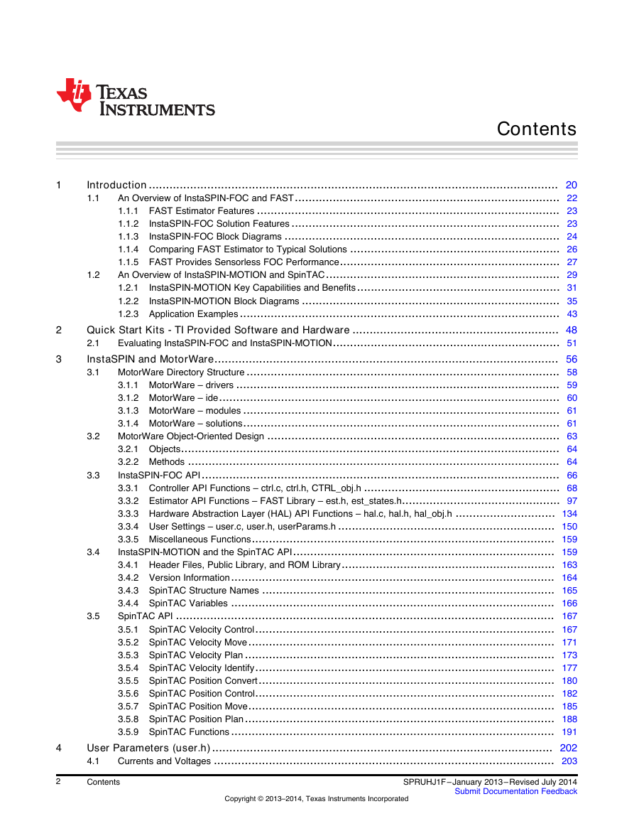
Contents 1 2 3 4 2 1.2 Introduction....................................................................................................................... 20 An Overview of InstaSPIN-FOC and FAST............................................................................. 22 1.1 1.1.1 FAST Estimator Features ........................................................................................ 23 1.1.2 InstaSPIN-FOC Solution Features .............................................................................. 23 1.1.3 InstaSPIN-FOC Block Diagrams ................................................................................ 24 1.1.4 Comparing FAST Estimator to Typical Solutions ............................................................. 26 1.1.5 FAST Provides Sensorless FOC Performance................................................................ 27 An Overview of InstaSPIN-MOTION and SpinTAC.................................................................... 29 1.2.1 InstaSPIN-MOTION Key Capabilities and Benefits........................................................... 31 1.2.2 InstaSPIN-MOTION Block Diagrams ........................................................................... 35 1.2.3 Application Examples............................................................................................. 43 Quick Start Kits - TI Provided Software and Hardware ............................................................ 48 Evaluating InstaSPIN-FOC and InstaSPIN-MOTION.................................................................. 51 2.1 InstaSPIN and MotorWare.................................................................................................... 56 MotorWare Directory Structure ........................................................................................... 58 3.1 3.1.1 MotorWare – drivers .............................................................................................. 59 3.1.2 MotorWare – ide................................................................................................... 60 3.1.3 MotorWare – modules ............................................................................................ 61 3.1.4 MotorWare – solutions............................................................................................ 61 MotorWare Object-Oriented Design ..................................................................................... 63 3.2.1 Objects.............................................................................................................. 64 3.2.2 Methods ............................................................................................................ 64 InstaSPIN-FOC API........................................................................................................ 66 3.3.1 Controller API Functions – ctrl.c, ctrl.h, CTRL_obj.h ......................................................... 68 3.3.2 Estimator API Functions – FAST Library – est.h, est_states.h.............................................. 97 3.3.3 Hardware Abstraction Layer (HAL) API Functions – hal.c, hal.h, hal_obj.h ............................. 134 3.3.4 User Settings – user.c, user.h, userParams.h ............................................................... 150 3.3.5 Miscellaneous Functions........................................................................................ 159 InstaSPIN-MOTION and the SpinTAC API............................................................................ 159 3.4.1 Header Files, Public Library, and ROM Library.............................................................. 163 3.4.2 Version Information.............................................................................................. 164 3.4.3 SpinTAC Structure Names ..................................................................................... 165 3.4.4 SpinTAC Variables .............................................................................................. 166 SpinTAC API .............................................................................................................. 167 3.5.1 SpinTAC Velocity Control....................................................................................... 167 3.5.2 SpinTAC Velocity Move......................................................................................... 171 3.5.3 SpinTAC Velocity Plan .......................................................................................... 173 3.5.4 SpinTAC Velocity Identify....................................................................................... 177 3.5.5 SpinTAC Position Convert...................................................................................... 180 3.5.6 SpinTAC Position Control....................................................................................... 182 3.5.7 SpinTAC Position Move......................................................................................... 185 3.5.8 SpinTAC Position Plan.......................................................................................... 188 3.5.9 SpinTAC Functions.............................................................................................. 191 User Parameters (user.h)................................................................................................... 202 Currents and Voltages ................................................................................................... 203 4.1 3.4 3.2 3.3 3.5 Contents Copyright © 2013–2014, Texas Instruments Incorporated SPRUHJ1F–January 2013–Revised July 2014 Submit Documentation Feedback
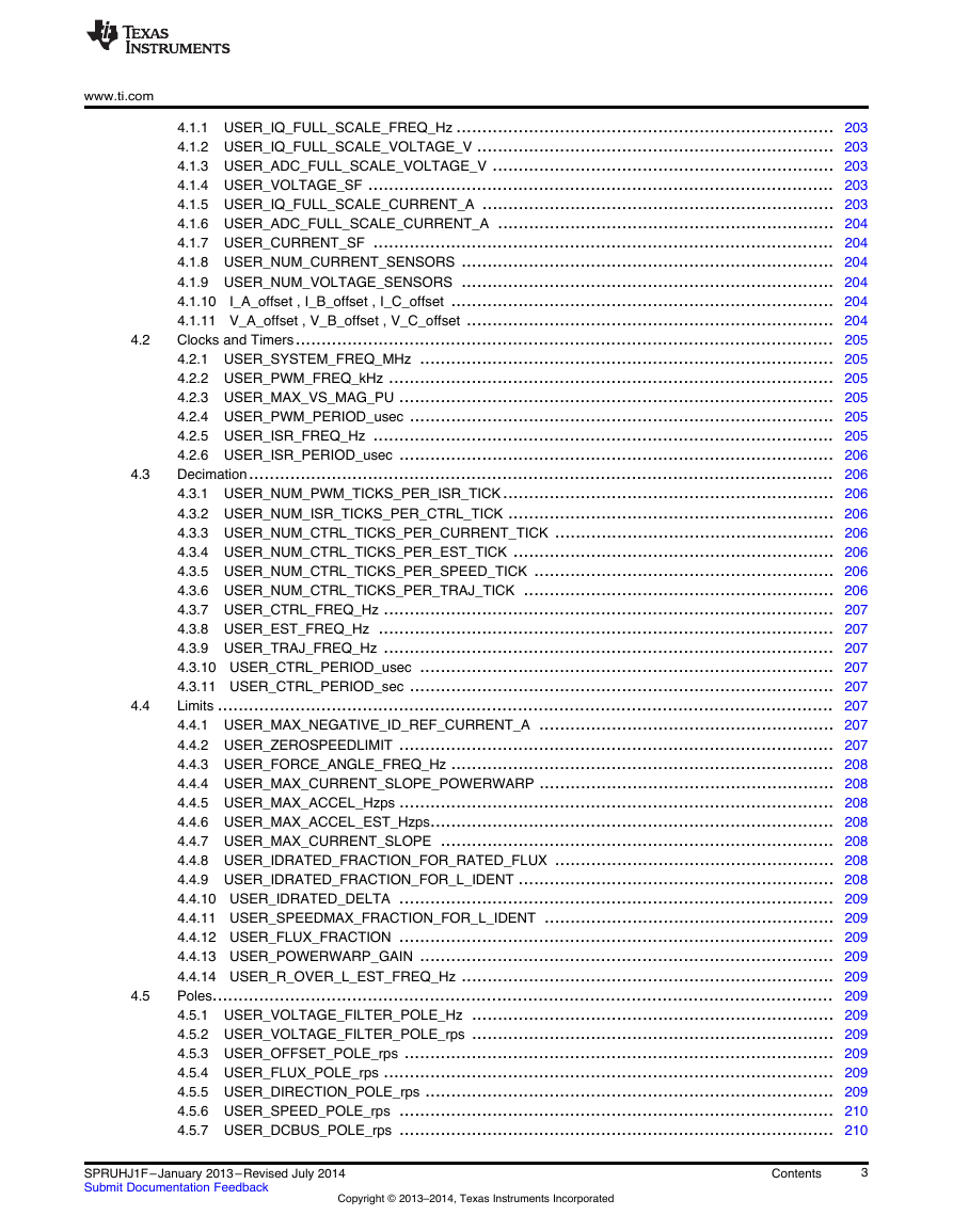
www.ti.com 4.1.1 USER_IQ_FULL_SCALE_FREQ_Hz ......................................................................... 203 4.1.2 USER_IQ_FULL_SCALE_VOLTAGE_V ..................................................................... 203 4.1.3 USER_ADC_FULL_SCALE_VOLTAGE_V .................................................................. 203 4.1.4 USER_VOLTAGE_SF .......................................................................................... 203 4.1.5 USER_IQ_FULL_SCALE_CURRENT_A .................................................................... 203 4.1.6 USER_ADC_FULL_SCALE_CURRENT_A ................................................................. 204 4.1.7 USER_CURRENT_SF ......................................................................................... 204 4.1.8 USER_NUM_CURRENT_SENSORS ........................................................................ 204 4.1.9 USER_NUM_VOLTAGE_SENSORS ........................................................................ 204 4.1.10 I_A_offset , I_B_offset , I_C_offset .......................................................................... 204 4.1.11 V_A_offset , V_B_offset , V_C_offset ....................................................................... 204 Clocks and Timers........................................................................................................ 205 4.2.1 USER_SYSTEM_FREQ_MHz ................................................................................ 205 4.2.2 USER_PWM_FREQ_kHz ...................................................................................... 205 4.2.3 USER_MAX_VS_MAG_PU .................................................................................... 205 4.2.4 USER_PWM_PERIOD_usec .................................................................................. 205 4.2.5 USER_ISR_FREQ_Hz ......................................................................................... 205 4.2.6 USER_ISR_PERIOD_usec .................................................................................... 206 Decimation................................................................................................................. 206 4.3.1 USER_NUM_PWM_TICKS_PER_ISR_TICK................................................................ 206 4.3.2 USER_NUM_ISR_TICKS_PER_CTRL_TICK ............................................................... 206 4.3.3 USER_NUM_CTRL_TICKS_PER_CURRENT_TICK ...................................................... 206 4.3.4 USER_NUM_CTRL_TICKS_PER_EST_TICK .............................................................. 206 4.3.5 USER_NUM_CTRL_TICKS_PER_SPEED_TICK .......................................................... 206 4.3.6 USER_NUM_CTRL_TICKS_PER_TRAJ_TICK ............................................................ 206 4.3.7 USER_CTRL_FREQ_Hz ....................................................................................... 207 4.3.8 USER_EST_FREQ_Hz ........................................................................................ 207 4.3.9 USER_TRAJ_FREQ_Hz ....................................................................................... 207 4.3.10 USER_CTRL_PERIOD_usec ................................................................................ 207 4.3.11 USER_CTRL_PERIOD_sec .................................................................................. 207 Limits ....................................................................................................................... 207 4.4.1 USER_MAX_NEGATIVE_ID_REF_CURRENT_A ......................................................... 207 4.4.2 USER_ZEROSPEEDLIMIT .................................................................................... 207 4.4.3 USER_FORCE_ANGLE_FREQ_Hz .......................................................................... 208 4.4.4 USER_MAX_CURRENT_SLOPE_POWERWARP ......................................................... 208 4.4.5 USER_MAX_ACCEL_Hzps .................................................................................... 208 4.4.6 USER_MAX_ACCEL_EST_Hzps.............................................................................. 208 4.4.7 USER_MAX_CURRENT_SLOPE ............................................................................ 208 4.4.8 USER_IDRATED_FRACTION_FOR_RATED_FLUX ...................................................... 208 4.4.9 USER_IDRATED_FRACTION_FOR_L_IDENT ............................................................. 208 4.4.10 USER_IDRATED_DELTA .................................................................................... 209 4.4.11 USER_SPEEDMAX_FRACTION_FOR_L_IDENT ........................................................ 209 4.4.12 USER_FLUX_FRACTION .................................................................................... 209 4.4.13 USER_POWERWARP_GAIN ................................................................................ 209 4.4.14 USER_R_OVER_L_EST_FREQ_Hz ........................................................................ 209 Poles........................................................................................................................ 209 4.5.1 USER_VOLTAGE_FILTER_POLE_Hz ...................................................................... 209 4.5.2 USER_VOLTAGE_FILTER_POLE_rps ...................................................................... 209 4.5.3 USER_OFFSET_POLE_rps ................................................................................... 209 4.5.4 USER_FLUX_POLE_rps ....................................................................................... 209 4.5.5 USER_DIRECTION_POLE_rps ............................................................................... 209 4.5.6 USER_SPEED_POLE_rps .................................................................................... 210 4.5.7 USER_DCBUS_POLE_rps .................................................................................... 210 4.2 4.3 4.4 4.5 SPRUHJ1F–January 2013–Revised July 2014 Submit Documentation Feedback Copyright © 2013–2014, Texas Instruments Incorporated Contents 3
4.6 www.ti.com 4.5.8 USER_EST_KAPPAQ .......................................................................................... 210 User Motor and ID Settings ............................................................................................. 210 4.6.1 USER_MOTOR_TYPE ......................................................................................... 210 4.6.2 USER_MOTOR_NUM_POLE_PAIRS ....................................................................... 210 4.6.3 USER_MOTOR_Rr ............................................................................................. 210 4.6.4 USER_MOTOR_Rs ............................................................................................. 210 4.6.5 USER_MOTOR_Ls_d .......................................................................................... 210 4.6.6 USER_MOTOR_Ls_q .......................................................................................... 210 4.6.7 USER_MOTOR_RATED_FLUX .............................................................................. 210 4.6.8 USER_VOLTAGE_FILTER_POLE_Hz ...................................................................... 210 4.6.9 USER_MOTOR_RES_EST_CURRENT ..................................................................... 211 4.6.10 USER_MOTOR_IND_EST_CURRENT ..................................................................... 211 4.6.11 USER_MOTOR_MAX_CURRENT .......................................................................... 211 4.6.12 USER_MOTOR_FLUX_EST_FREQ_Hz ................................................................... 211 4.6.13 USER_MOTOR_ENCODER_LINES (InstaSPIN-MOTION Only) ........................................ 211 4.6.14 USER_MOTOR_MAX_SPEED_KRPM (InstaSPIN-MOTION Only) ..................................... 211 4.6.15 USER_SYSTEM_INERTIA (InstaSPIN-MOTION Only) ................................................... 211 4.6.16 USER_SYSTEM_FRICTION (InstaSPIN-MOTION Only) ................................................. 211 4.6.17 USER_SYSTEM_BANDWIDTH_SCALE (InstaSPIN-MOTION Only) ................................... 211 SpinTAC Parameters (spintac_velocity.h and spintac_position.h) ................................................. 212 4.7.1 Macro Definitions ................................................................................................ 212 4.7.2 Type Definitions.................................................................................................. 213 4.7.3 Functions.......................................................................................................... 214 Setting ACIM Motor Parameters in user.h............................................................................. 216 4.8.1 Getting Parameters From an ACIM Datasheet .............................................................. 217 Managing Motor Signals .................................................................................................... 220 Software Prerequisites ................................................................................................... 221 5.1 5.1.1 IQ Full-Scale Frequency ........................................................................................ 221 5.1.2 IQ Full-Scale Voltage............................................................................................ 221 5.1.3 IQ Full-Scale Current............................................................................................ 223 5.1.4 Max Current ...................................................................................................... 223 5.1.5 Decimation Rates................................................................................................ 224 5.1.6 System Frequency............................................................................................... 225 5.1.7 PWM Frequency ................................................................................................. 225 5.1.8 Max Voltage Vector.............................................................................................. 225 Hardware Prerequisites .................................................................................................. 226 5.2.1 Current Feedback Gain ......................................................................................... 227 5.2.2 Current Feedback Polarity...................................................................................... 228 5.2.3 Voltage Feedback ............................................................................................... 230 5.2.4 Voltage Filter Pole ............................................................................................... 232 5.2.5 Number of Shunt Resistors..................................................................................... 233 5.2.6 Deadtime Configuration......................................................................................... 233 5.2.7 Analog Inputs Configuration.................................................................................... 235 5.2.8 PWM Outputs Configuration.................................................................................... 236 Motor Identification and State Diagrams.............................................................................. 237 InstaSPIN Motor Identification .......................................................................................... 238 6.1 Motor Identification Process Overview................................................................................. 240 6.2 6.2.1 Controller (CTRL) State Machine.............................................................................. 240 6.2.2 Estimator (EST) State Machine................................................................................ 243 6.2.3 Controller (CTRL) and Estimator (EST) State Machine Dependencies .................................. 245 Differences between PMSM and ACIM Identification Process ..................................................... 246 Prerequisites............................................................................................................... 247 6.4.1 Mechanical Prerequisites ....................................................................................... 247 6.3 6.4 4.7 4.8 5.2 5 6 4 Contents Copyright © 2013–2014, Texas Instruments Incorporated SPRUHJ1F–January 2013–Revised July 2014 Submit Documentation Feedback
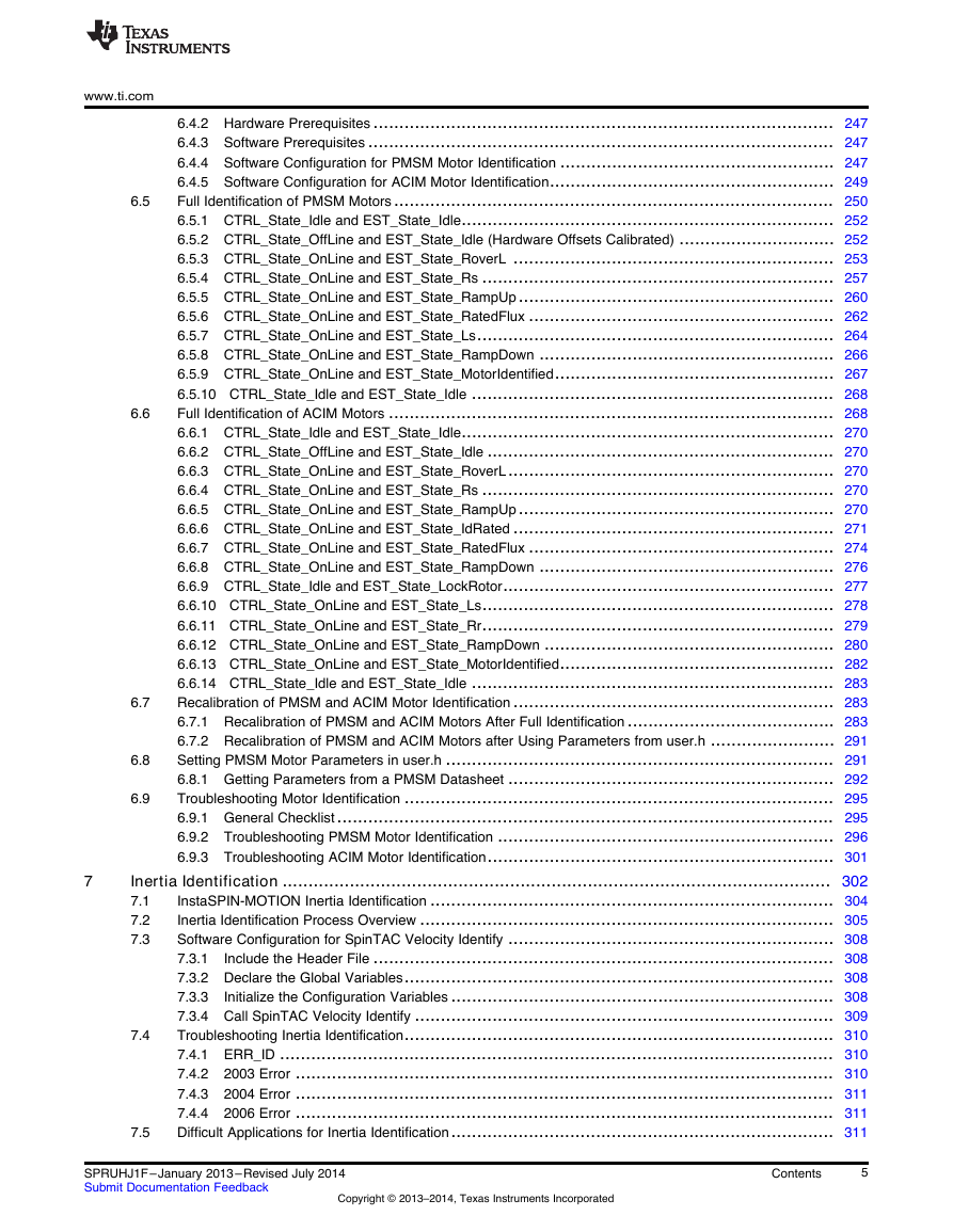
www.ti.com 6.6 6.5 6.4.2 Hardware Prerequisites ......................................................................................... 247 6.4.3 Software Prerequisites .......................................................................................... 247 6.4.4 Software Configuration for PMSM Motor Identification ..................................................... 247 6.4.5 Software Configuration for ACIM Motor Identification....................................................... 249 Full Identification of PMSM Motors..................................................................................... 250 6.5.1 CTRL_State_Idle and EST_State_Idle........................................................................ 252 6.5.2 CTRL_State_OffLine and EST_State_Idle (Hardware Offsets Calibrated) .............................. 252 6.5.3 CTRL_State_OnLine and EST_State_RoverL .............................................................. 253 6.5.4 CTRL_State_OnLine and EST_State_Rs .................................................................... 257 6.5.5 CTRL_State_OnLine and EST_State_RampUp............................................................. 260 6.5.6 CTRL_State_OnLine and EST_State_RatedFlux ........................................................... 262 6.5.7 CTRL_State_OnLine and EST_State_Ls..................................................................... 264 6.5.8 CTRL_State_OnLine and EST_State_RampDown ......................................................... 266 6.5.9 CTRL_State_OnLine and EST_State_MotorIdentified...................................................... 267 6.5.10 CTRL_State_Idle and EST_State_Idle ...................................................................... 268 Full Identification of ACIM Motors ...................................................................................... 268 6.6.1 CTRL_State_Idle and EST_State_Idle........................................................................ 270 6.6.2 CTRL_State_OffLine and EST_State_Idle ................................................................... 270 6.6.3 CTRL_State_OnLine and EST_State_RoverL............................................................... 270 6.6.4 CTRL_State_OnLine and EST_State_Rs .................................................................... 270 6.6.5 CTRL_State_OnLine and EST_State_RampUp............................................................. 270 6.6.6 CTRL_State_OnLine and EST_State_IdRated .............................................................. 271 6.6.7 CTRL_State_OnLine and EST_State_RatedFlux ........................................................... 274 6.6.8 CTRL_State_OnLine and EST_State_RampDown ......................................................... 276 6.6.9 CTRL_State_Idle and EST_State_LockRotor................................................................ 277 6.6.10 CTRL_State_OnLine and EST_State_Ls.................................................................... 278 6.6.11 CTRL_State_OnLine and EST_State_Rr.................................................................... 279 6.6.12 CTRL_State_OnLine and EST_State_RampDown ........................................................ 280 6.6.13 CTRL_State_OnLine and EST_State_MotorIdentified..................................................... 282 6.6.14 CTRL_State_Idle and EST_State_Idle ...................................................................... 283 Recalibration of PMSM and ACIM Motor Identification .............................................................. 283 6.7.1 Recalibration of PMSM and ACIM Motors After Full Identification ........................................ 283 6.7.2 Recalibration of PMSM and ACIM Motors after Using Parameters from user.h ........................ 291 Setting PMSM Motor Parameters in user.h ........................................................................... 291 6.8.1 Getting Parameters from a PMSM Datasheet ............................................................... 292 Troubleshooting Motor Identification ................................................................................... 295 6.9.1 General Checklist................................................................................................ 295 6.9.2 Troubleshooting PMSM Motor Identification ................................................................. 296 6.9.3 Troubleshooting ACIM Motor Identification................................................................... 301 Inertia Identification .......................................................................................................... 302 InstaSPIN-MOTION Inertia Identification .............................................................................. 304 7.1 Inertia Identification Process Overview ................................................................................ 305 7.2 Software Configuration for SpinTAC Velocity Identify ............................................................... 308 7.3 7.3.1 Include the Header File ......................................................................................... 308 7.3.2 Declare the Global Variables................................................................................... 308 7.3.3 Initialize the Configuration Variables .......................................................................... 308 7.3.4 Call SpinTAC Velocity Identify ................................................................................. 309 Troubleshooting Inertia Identification................................................................................... 310 7.4.1 ERR_ID ........................................................................................................... 310 7.4.2 2003 Error ........................................................................................................ 310 7.4.3 2004 Error ........................................................................................................ 311 7.4.4 2006 Error ........................................................................................................ 311 Difficult Applications for Inertia Identification.......................................................................... 311 7.5 6.7 6.8 6.9 7.4 7 SPRUHJ1F–January 2013–Revised July 2014 Submit Documentation Feedback Copyright © 2013–2014, Texas Instruments Incorporated Contents 5
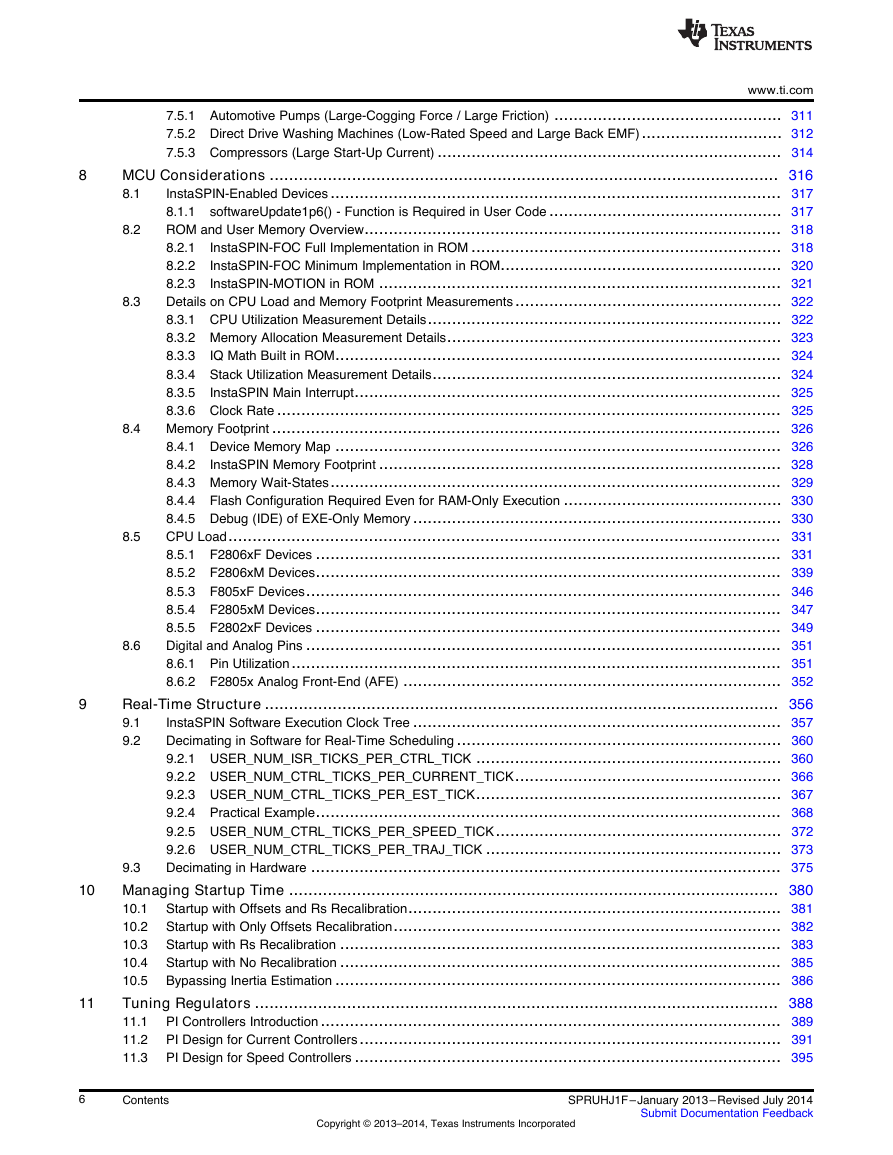
8.4 8.5 8.6 8.3 8.2 www.ti.com 7.5.1 Automotive Pumps (Large-Cogging Force / Large Friction) ............................................... 311 7.5.2 Direct Drive Washing Machines (Low-Rated Speed and Large Back EMF)............................. 312 7.5.3 Compressors (Large Start-Up Current) ....................................................................... 314 MCU Considerations ......................................................................................................... 316 InstaSPIN-Enabled Devices............................................................................................. 317 8.1 8.1.1 softwareUpdate1p6() - Function is Required in User Code ................................................ 317 ROM and User Memory Overview...................................................................................... 318 8.2.1 InstaSPIN-FOC Full Implementation in ROM ................................................................ 318 8.2.2 InstaSPIN-FOC Minimum Implementation in ROM.......................................................... 320 8.2.3 InstaSPIN-MOTION in ROM ................................................................................... 321 Details on CPU Load and Memory Footprint Measurements....................................................... 322 8.3.1 CPU Utilization Measurement Details......................................................................... 322 8.3.2 Memory Allocation Measurement Details..................................................................... 323 8.3.3 IQ Math Built in ROM............................................................................................ 324 8.3.4 Stack Utilization Measurement Details........................................................................ 324 8.3.5 InstaSPIN Main Interrupt........................................................................................ 325 8.3.6 Clock Rate ........................................................................................................ 325 Memory Footprint ......................................................................................................... 326 8.4.1 Device Memory Map ............................................................................................ 326 8.4.2 InstaSPIN Memory Footprint ................................................................................... 328 8.4.3 Memory Wait-States............................................................................................. 329 8.4.4 Flash Configuration Required Even for RAM-Only Execution ............................................. 330 8.4.5 Debug (IDE) of EXE-Only Memory............................................................................ 330 CPU Load.................................................................................................................. 331 8.5.1 F2806xF Devices ................................................................................................ 331 8.5.2 F2806xM Devices................................................................................................ 339 8.5.3 F805xF Devices.................................................................................................. 346 8.5.4 F2805xM Devices................................................................................................ 347 8.5.5 F2802xF Devices ................................................................................................ 349 Digital and Analog Pins .................................................................................................. 351 8.6.1 Pin Utilization..................................................................................................... 351 8.6.2 F2805x Analog Front-End (AFE) .............................................................................. 352 Real-Time Structure .......................................................................................................... 356 InstaSPIN Software Execution Clock Tree ............................................................................ 357 9.1 Decimating in Software for Real-Time Scheduling ................................................................... 360 9.2 9.2.1 USER_NUM_ISR_TICKS_PER_CTRL_TICK ............................................................... 360 9.2.2 USER_NUM_CTRL_TICKS_PER_CURRENT_TICK....................................................... 366 9.2.3 USER_NUM_CTRL_TICKS_PER_EST_TICK............................................................... 367 9.2.4 Practical Example................................................................................................ 368 9.2.5 USER_NUM_CTRL_TICKS_PER_SPEED_TICK........................................................... 372 9.2.6 USER_NUM_CTRL_TICKS_PER_TRAJ_TICK ............................................................. 373 Decimating in Hardware ................................................................................................. 375 9.3 Managing Startup Time ..................................................................................................... 380 Startup with Offsets and Rs Recalibration............................................................................. 381 10.1 Startup with Only Offsets Recalibration................................................................................ 382 10.2 Startup with Rs Recalibration ........................................................................................... 383 10.3 Startup with No Recalibration ........................................................................................... 385 10.4 Bypassing Inertia Estimation ............................................................................................ 386 10.5 Tuning Regulators ............................................................................................................ 388 PI Controllers Introduction............................................................................................... 389 11.1 PI Design for Current Controllers....................................................................................... 391 11.2 PI Design for Speed Controllers ........................................................................................ 395 11.3 8 9 10 11 6 Contents Copyright © 2013–2014, Texas Instruments Incorporated SPRUHJ1F–January 2013–Revised July 2014 Submit Documentation Feedback
www.ti.com 12 13 12.2 11.9 11.4 Calculating PI Gains Based On Stability and Bandwidth............................................................ 397 11.5 Calculating Speed and Current PI Gains Based on Damping Factor.............................................. 399 11.6 Considerations When Adding Poles to the Speed Loop............................................................. 404 Speed PI Controller Considerations: Current Limits, Clamping and Inertia....................................... 406 11.7 11.8 Considerations When Designing PI Controllers for FOC Systems................................................. 409 11.8.1 FOC Differences Between Motor Types..................................................................... 410 11.8.2 Coupling Between Q-Axis and D-Axis ....................................................................... 410 Sampling and Digital Systems Considerations ....................................................................... 413 11.9.1 Sampling Period Considerations in the Integral Gain...................................................... 417 11.9.2 Number Format Considerations .............................................................................. 417 11.9.3 PI Coefficients Scaling Considerations ...................................................................... 418 InstaSPIN-MOTION Controllers........................................................................................... 419 Stability..................................................................................................................... 420 12.1 12.1.1 Quantifying Stability ............................................................................................ 420 12.1.2 Performance..................................................................................................... 422 12.1.3 Trade-Off Between Stability and Performance.............................................................. 424 12.1.4 Tuning the SpinTAC Controller ............................................................................... 424 Software Configuration for the SpinTAC Velocity Control........................................................... 426 12.2.1 Include the Header File ........................................................................................ 426 12.2.2 Declare the Global Structure.................................................................................. 427 12.2.3 Initialize the Configuration Variables ......................................................................... 427 12.2.4 Call SpinTAC Velocity Control ................................................................................ 428 12.2.5 Troubleshooting SpinTAC Velocity Control ................................................................. 428 12.3 Optimal Performance in Speed Control................................................................................ 429 12.3.1 Introduction ...................................................................................................... 429 12.3.2 Comparing Speed Controllers................................................................................. 429 12.3.3 Disturbance Rejection.......................................................................................... 429 12.3.4 Profile Tracking ................................................................................................. 431 12.3.5 InstaSPIN-MOTION Velocity Control Advantage........................................................... 433 Software Configuration for SpinTAC Position Control ............................................................... 438 12.4.1 Include the Header File ........................................................................................ 438 12.4.2 Declare the Global Structure.................................................................................. 439 12.4.3 Initialize the Configuration Variables ......................................................................... 439 12.4.4 Call SpinTAC Position Control ................................................................................ 440 12.4.5 Troubleshooting SpinTAC Position Control ................................................................. 440 12.5 Optimal Performance in Position Control.............................................................................. 441 12.5.1 Introduction ...................................................................................................... 441 12.5.2 Comparing Position Controllers............................................................................... 441 12.5.3 Disturbance Rejection.......................................................................................... 441 12.5.4 Profile Tracking ................................................................................................. 443 12.5.5 InstaSPIN-MOTION Position Control Advantage........................................................... 445 Trajectory Planning........................................................................................................... 451 InstaSPIN-MOTION Profile Generation................................................................................ 452 13.1 13.1.1 Jerk Impact on System Performance ........................................................................ 452 Software Configuration for SpinTAC Velocity Move.................................................................. 453 13.2.1 Include the Header File ........................................................................................ 453 13.2.2 Declare the Global Structure.................................................................................. 454 13.2.3 Initialize the Configuration Variables ......................................................................... 454 13.2.4 Call SpinTAC Velocity Move .................................................................................. 454 13.2.5 Troubleshooting SpinTAC Velocity Move.................................................................... 455 Software Configuration for SpinTAC Position Move ................................................................. 456 13.3.1 Include the Header File ........................................................................................ 456 13.3.2 Declare the Global Structure.................................................................................. 456 12.4 13.2 13.3 SPRUHJ1F–January 2013–Revised July 2014 Submit Documentation Feedback Copyright © 2013–2014, Texas Instruments Incorporated Contents 7
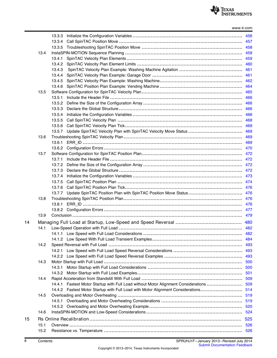
13.6 13.7 13.8 13.5 13.4 www.ti.com 13.3.3 Initialize the Configuration Variables ......................................................................... 456 13.3.4 Call SpinTAC Position Move .................................................................................. 457 13.3.5 Troubleshooting SpinTAC Position Move ................................................................... 458 InstaSPIN-MOTION Sequence Planning .............................................................................. 459 13.4.1 SpinTAC Velocity Plan Elements............................................................................. 459 13.4.2 SpinTAC Velocity Plan Element Limits ...................................................................... 460 13.4.3 SpinTAC Velocity Plan Example: Washing Machine Agitation .......................................... 461 13.4.4 SpinTAC Velocity Plan Example: Garage Door ............................................................ 461 13.4.5 SpinTAC Velocity Plan Example: Washing Machine....................................................... 462 13.4.6 SpinTAC Position Plan Example: Vending Machine ....................................................... 464 Software Configuration for SpinTAC Velocity Plan................................................................... 465 13.5.1 Include the Header File ........................................................................................ 466 13.5.2 Define the Size of the Configuration Array .................................................................. 466 13.5.3 Declare the Global Structure.................................................................................. 466 13.5.4 Initialize the Configuration Variables ......................................................................... 466 13.5.5 Call SpinTAC Velocity Plan ................................................................................... 468 13.5.6 Call SpinTAC Velocity Plan Tick.............................................................................. 469 13.5.7 Update SpinTAC Velocity Plan with SpinTAC Velocity Move Status .................................... 469 Troubleshooting SpinTAC Velocity Plan............................................................................... 469 13.6.1 ERR_ID .......................................................................................................... 469 13.6.2 Configuration Errors ............................................................................................ 470 Software Configuration for SpinTAC Position Plan................................................................... 472 13.7.1 Include the Header File ........................................................................................ 472 13.7.2 Define the Size of the Configuration Array .................................................................. 472 13.7.3 Declare the Global Structure.................................................................................. 472 13.7.4 Initialize the Configuration Variables ......................................................................... 473 13.7.5 Call SpinTAC Position Plan ................................................................................... 474 13.7.6 Call SpinTAC Position Plan Tick.............................................................................. 476 13.7.7 Update SpinTAC Position Plan with SpinTAC Position Move Status.................................... 476 Troubleshooting SpinTAC Position Plan............................................................................... 476 13.8.1 ERR_ID .......................................................................................................... 476 13.8.2 Configuration Errors ............................................................................................ 477 13.9 Conclusion................................................................................................................. 479 Managing Full Load at Startup, Low-Speed and Speed Reversal ............................................ 480 Low-Speed Operation with Full Load .................................................................................. 482 14.1 14.1.1 Low Speed with Full Load Considerations .................................................................. 482 14.1.2 Low Speed With Full Load Transient Examples............................................................ 484 Speed Reversal with Full Load ......................................................................................... 493 14.2.1 Low Speed with Full Load Speed Reversal Considerations .............................................. 493 14.2.2 Low Speed with Full Load Speed Reversal Examples .................................................... 493 14.3 Motor Startup with Full Load ............................................................................................ 500 14.3.1 Motor Startup with Full Load Considerations ............................................................... 500 14.3.2 Motor Startup with Full Load Examples...................................................................... 501 14.4 Rapid Acceleration from Standstill With Full Load ................................................................... 509 14.4.1 Fastest Motor Startup with Full Load without Motor Alignment Considerations........................ 509 14.4.2 Fastest Motor Startup with Full Load with Motor Alignment Considerations............................ 514 14.5 Overloading and Motor Overheating ................................................................................... 519 14.5.1 Overloading and Motor Overheating Considerations ...................................................... 519 14.5.2 Overloading and Motor Overheating Example.............................................................. 520 InstaSPIN-MOTION and Low-Speed Considerations................................................................ 524 14.6 Rs Online Recalibration..................................................................................................... 525 15.1 Overview ................................................................................................................... 526 15.2 Resistance vs. Temperature ............................................................................................ 526 14.2 14 15 8 Contents Copyright © 2013–2014, Texas Instruments Incorporated SPRUHJ1F–January 2013–Revised July 2014 Submit Documentation Feedback
分享到:
收藏