OEM PRODUCT DESIGN GUIDE
NVIDIA Jetson TX2
Abstract
This document contains recommendations and guidelines for Engineers to follow to create a product that is optimized
to achieve the best performance from the common interfaces supported by the NVIDIA® Jetson™ TX2 System-on-
Module (SOM).
Note:
Jetson TX2 utilizes Tegra X2 which is a Parker series SoC.
JETSON TX2 OEM PRODUCT | DESIGN GUIDE | 20170912
1
�
NVIDIA Jetson TX2 OEM Product Design Guide
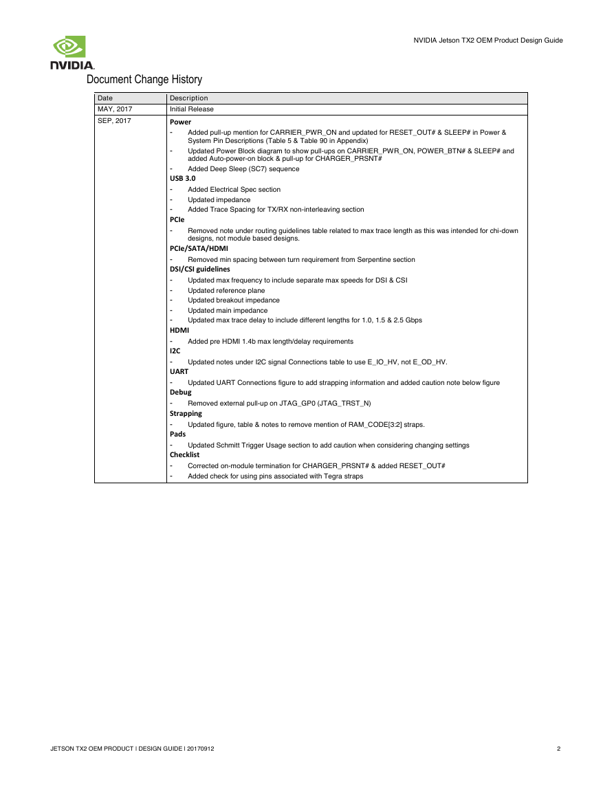
Document Change History
Date
MAY, 2017
SEP, 2017
Description
Initial Release
Power
-
Added pull-up mention for CARRIER_PWR_ON and updated for RESET_OUT# & SLEEP# in Power &
System Pin Descriptions (Table 5 & Table 90 in Appendix)
-
Updated Power Block diagram to show pull-ups on CARRIER_PWR_ON, POWER_BTN# & SLEEP# and
added Auto-power-on block & pull-up for CHARGER_PRSNT#
Added Deep Sleep (SC7) sequence
Added Electrical Spec section
Updated impedance
Added Trace Spacing for TX/RX non-interleaving section
Removed note under routing guidelines table related to max trace length as this was intended for chi-down
designs, not module based designs.
-
USB 3.0
-
-
-
PCIe
-
PCIe/SATA/HDMI
-
DSI/CSI guidelines
-
-
-
-
-
HDMI
-
I2C
-
UART
-
Debug
-
Strapping
-
Pads
-
Checklist
-
-
Removed min spacing between turn requirement from Serpentine section
Updated max frequency to include separate max speeds for DSI & CSI
Updated reference plane
Updated breakout impedance
Updated main impedance
Updated max trace delay to include different lengths for 1.0, 1.5 & 2.5 Gbps
Added pre HDMI 1.4b max length/delay requirements
Updated notes under I2C signal Connections table to use E_IO_HV, not E_OD_HV.
Updated UART Connections figure to add strapping information and added caution note below figure
Removed external pull-up on JTAG_GP0 (JTAG_TRST_N)
Updated figure, table & notes to remove mention of RAM_CODE[3:2] straps.
Updated Schmitt Trigger Usage section to add caution when considering changing settings
Corrected on-module termination for CHARGER_PRSNT# & added RESET_OUT#
Added check for using pins associated with Tegra straps
JETSON TX2 OEM PRODUCT | DESIGN GUIDE | 20170912
2
�
NVIDIA Jetson TX2 OEM Product Design Guide
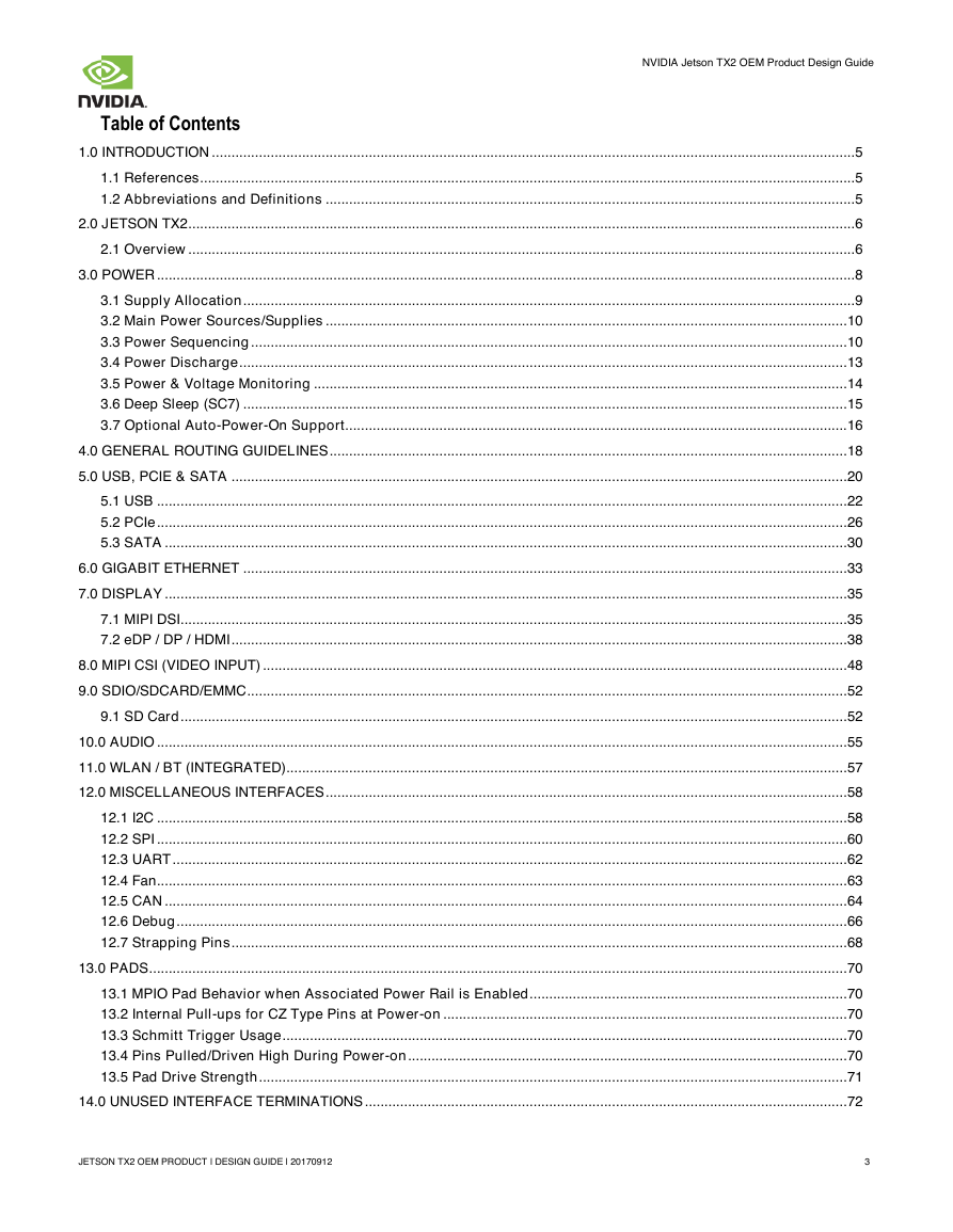
Table of Contents
1.0 INTRODUCTION ....................................................................................................................................................................5
1.1 References .......................................................................................................................................................................5
1.2 Abbreviations and Definitions .......................................................................................................................................5
2.0 JETSON TX2 ..........................................................................................................................................................................6
2.1 Overview ..........................................................................................................................................................................6
3.0 POWER ..................................................................................................................................................................................8
3.1 Supply Allocation ............................................................................................................................................................9
3.2 Main Power Sources/Supplies ..................................................................................................................................... 10
3.3 Power Sequencing ........................................................................................................................................................ 10
3.4 Power Discharge ........................................................................................................................................................... 13
3.5 Power & Voltage Monitoring ........................................................................................................................................ 14
3.6 Deep Sleep (SC7) .......................................................................................................................................................... 15
3.7 Optional Auto-Power-On Support................................................................................................................................ 16
4.0 GENERAL ROUTING GUIDELINES .................................................................................................................................... 18
5.0 USB, PCIE & SATA ............................................................................................................................................................. 20
5.1 USB ................................................................................................................................................................................ 22
5.2 PCIe ................................................................................................................................................................................ 26
5.3 SATA .............................................................................................................................................................................. 30
6.0 GIGABIT ETHERNET .......................................................................................................................................................... 33
7.0 DISPLAY .............................................................................................................................................................................. 35
7.1 MIPI DSI .......................................................................................................................................................................... 35
7.2 eDP / DP / HDMI ............................................................................................................................................................. 38
8.0 MIPI CSI (VIDEO INPUT) ..................................................................................................................................................... 48
9.0 SDIO/SDCARD/EMMC ......................................................................................................................................................... 52
9.1 SD Card .......................................................................................................................................................................... 52
10.0 AUDIO ................................................................................................................................................................................ 55
11.0 WLAN / BT (INTEGRATED) ............................................................................................................................................... 57
12.0 MISCELLANEOUS INTERFACES ..................................................................................................................................... 58
12.1 I2C ................................................................................................................................................................................ 58
12.2 SPI ................................................................................................................................................................................ 60
12.3 UART ............................................................................................................................................................................ 62
12.4 Fan................................................................................................................................................................................ 63
12.5 CAN .............................................................................................................................................................................. 64
12.6 Debug ........................................................................................................................................................................... 66
12.7 Strapping Pins ............................................................................................................................................................. 68
13.0 PADS .................................................................................................................................................................................. 70
13.1 MPIO Pad Behavior when Associated Power Rail is Enabled ................................................................................. 70
13.2 Internal Pull-ups for CZ Type Pins at Power-on ....................................................................................................... 70
13.3 Schmitt Trigger Usage ................................................................................................................................................ 70
13.4 Pins Pulled/Driven High During Power-on ................................................................................................................ 70
13.5 Pad Drive Strength ...................................................................................................................................................... 71
14.0 UNUSED INTERFACE TERMINATIONS ........................................................................................................................... 72
JETSON TX2 OEM PRODUCT | DESIGN GUIDE | 20170912
3
�
NVIDIA Jetson TX2 OEM Product Design Guide
14.1 Unused MPIO Interfaces ............................................................................................................................................. 72
14.2 Unused SFIO Interface Pins ....................................................................................................................................... 72
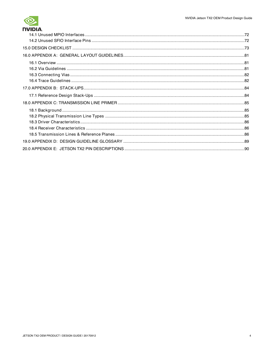
15.0 DESIGN CHECKLIST ........................................................................................................................................................ 73
16.0 APPENDIX A: GENERAL LAYOUT GUIDELINES ........................................................................................................... 81
16.1 Overview ...................................................................................................................................................................... 81
16.2 Via Guidelines ............................................................................................................................................................. 81
16.3 Connecting Vias .......................................................................................................................................................... 82
16.4 Trace Guidelines ......................................................................................................................................................... 82
17.0 APPENDIX B: STACK-UPS .............................................................................................................................................. 84
17.1 Reference Design Stack-Ups ..................................................................................................................................... 84
18.0 APPENDIX C: TRANSMISSION LINE PRIMER ................................................................................................................ 85
18.1 Background ................................................................................................................................................................. 85
18.2 Physical Transmission Line Types ........................................................................................................................... 85
18.3 Driver Characteristics ................................................................................................................................................. 86
18.4 Receiver Characteristics ............................................................................................................................................ 86
18.5 Transmission Lines & Reference Planes .................................................................................................................. 86
19.0 APPENDIX D: DESIGN GUIDELINE GLOSSARY ........................................................................................................... 89
20.0 APPENDIX E: JETSON TX2 PIN DESCRIPTIONS .......................................................................................................... 90
JETSON TX2 OEM PRODUCT | DESIGN GUIDE | 20170912
4
�
NVIDIA Jetson TX2 OEM Product Design Guide
1.0 INTRODUCTION
1.1 References
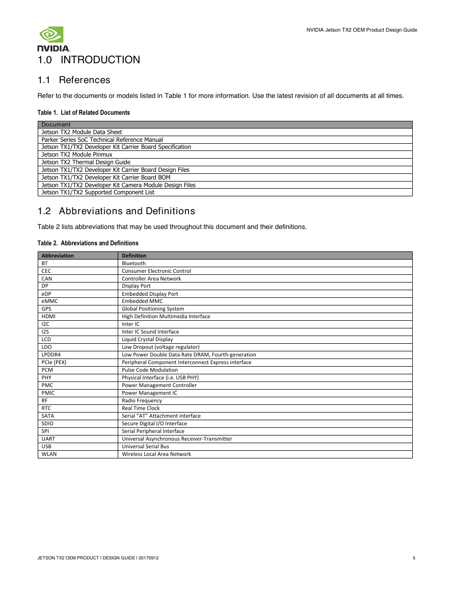
Refer to the documents or models listed in Table 1 for more information. Use the latest revision of all documents at all times.
Table 1. List of Related Documents
Document
Jetson TX2 Module Data Sheet
Parker Series SoC Technical Reference Manual
Jetson TX1/TX2 Developer Kit Carrier Board Specification
Jetson TX2 Module Pinmux
Jetson TX2 Thermal Design Guide
Jetson TX1/TX2 Developer Kit Carrier Board Design Files
Jetson TX1/TX2 Developer Kit Carrier Board BOM
Jetson TX1/TX2 Developer Kit Camera Module Design Files
Jetson TX1/TX2 Supported Component List
1.2 Abbreviations and Definitions
Table 2 lists abbreviations that may be used throughout this document and their definitions.
Table 2. Abbreviations and Definitions
Abbreviation
BT
CEC
CAN
DP
eDP
eMMC
GPS
HDMI
I2C
I2S
LCD
LDO
LPDDR4
PCIe (PEX)
PCM
PHY
PMC
PMIC
RF
RTC
SATA
SDIO
SPI
UART
USB
WLAN
Definition
Bluetooth
Consumer Electronic Control
Controller Area Network
Display Port
Embedded Display Port
Embedded MMC
Global Positioning System
High Definition Multimedia Interface
Inter IC
Inter IC Sound Interface
Liquid Crystal Display
Low Dropout (voltage regulator)
Low Power Double Data Rate DRAM, Fourth-generation
Peripheral Component Interconnect Express interface
Pulse Code Modulation
Physical Interface (i.e. USB PHY)
Power Management Controller
Power Management IC
Radio Frequency
Real Time Clock
Serial “AT” Attachment interface
Secure Digital I/O Interface
Serial Peripheral Interface
Universal Asynchronous Receiver-Transmitter
Universal Serial Bus
Wireless Local Area Network
JETSON TX2 OEM PRODUCT | DESIGN GUIDE | 20170912
5
�
NVIDIA Jetson TX2 OEM Product Design Guide
2.0 JETSON TX2
2.1 Overview
The Jetson TX2 resides at the center of the embedded system solution and includes:
Power (PMIC/Regulators, etc.)
1.
3. DRAM (LPDDR4)
5.
7. Connects to WLAN and Bluetooth enabled devices
eMMC
2. Ethernet PHY
4.
6. Thermal Sensor
Power & Voltage Monitors
In addition, a range of interfaces are available at the main connector for use on the carrier board as shown in the following table.
Table 3. Jetson TX2 Interfaces
Catagory
USB
PCIe
SATA
Camera
Display
Audio
SD Card
LAN
Function
USB 2.0 (3x)
USB 3.0 (up to 3x) see note
Control [x3] (shared Wake)
PCIe (3 root ports - See note)
SATA & Device Sleep control
CSI (6 x2 or 3 x4), Control, Clock
2x eDP/DP/HDMI
DSI (2 x4), Display/Backlight Control
I2S (4x), Control & Clock
Digital Mic & Speaker
SD Card or SDIO
Gigabit Ethernet
Catagory
CAN
I2C
UART
SPI
WLAN/BT/Modem
Touch
Sensor
Fan
Debug
System
Power
Function
2x
8x
5x
3x
PEX/UART/I2S, Control/handshake
Touch Clock, Interrupt & Reset
Control & Interrupt
FAN PWM & Tach Input
JTAG, UART
Power Control, Reset, Alerts
Main Input
Note:
Some USB 3.0 or PCIe instances are shared. Refer to Chapter 5.0 USB, PCIe & SATA for details.
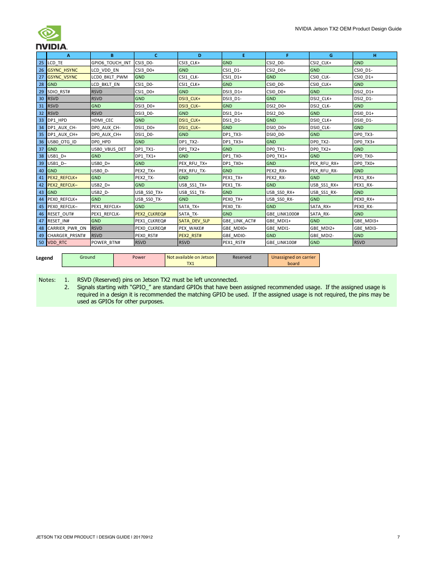
Table 4. Jetson TX2 Connector (8x50) Pin Out Matrix
A
1 VDD_IN
2 VDD_IN
3 GND
4 GND
5 RSVD
6
I2C_PM_CLK
7 CHARGING#
B
VDD_IN
VDD_IN
GND
GND
RSVD
I2C_PM_DAT
CARRIER_STBY#
C
VDD_IN
VDD_IN
GND
GND
RSVD
I2C_CAM_CLK
BATLOW#
D
E
F
RSVD
RSVD
RSVD
RSVD
UART7_RX
I2C_CAM_DAT
GPIO5_CAM_FLASH_EN CAM2_MCLK
FORCE_RECOV#
SLEEP#
SPI0_CLK
SPI0_MISO
I2S3_SDIN
I2S3_CLK
AUDIO_MCLK
GPIO19_AUD_RST
SPI0_CS0#
SPI0_MOSI
I2S3_LRCLK
I2S3_SDOUT
GPIO1_CAM1_PWR#
G
I2S0_SDIN
I2S0_CLK
GND
DSPK_OUT_CLK
I2S2_CLK
I2S2_SDIN
GPIO4_CAM_STROBE GPIO3_CAM1_RST#
H
I2S0_LRCLK
I2S0_SDOUT
GPIO20_AUD_INT
DSPK_OUT_DAT
I2S2_LRCLK
I2S2_SDOUT
8 GPIO14_AP_WAKE_MDM VIN_PWR_BAD#
BATT_OC
UART7_TX
CAM_VSYNC
CAM1_MCLK
GPIO0_CAM0_PWR#
GPIO2_CAM0_RST#
WDT_TIME_OUT# UART1_TX
UART1_RTS#
CAM0_MCLK
UART3_CTS#
UART3_RX
9
GPIO15_AP2MDM_
READY
GPIO16_MDM_
WAKE_AP
11 JTAG_GP1
10
GPIO17_MDM2AP_
READY
GPIO18_MDM_COL
DBOOT
JTAG_TCK
12 JTAG_TMS
13 JTAG_TDO
14 JTAG_RTCK
15 UART2_CTS#
16 UART2_RTS#
JTAG_TDI
JTAG_GP0
GND
UART2_RX
UART2_TX
17 USB0_EN_OC#
FAN_TACH
18 USB1_EN_OC#
RSVD
I2S1_SDIN
I2S1_CLK
FAN_PWM
CAN1_STBY
CAN1_TX
19 RSVD
GPIO11_AP_WAKE_BT CAN1_ERR
20
21
I2C_GP1_DAT
I2C_GP1_CLK
GPIO10_WIFI_WAKE_AP CAN_WAKE
GPIO12_BT_EN
GND
22 GPIO_EXP1_INT
GPIO13_BT_WAKE_AP CSI5_D0-
23 GPIO_EXP0_INT
24 LCD1_BKLT_PWM
GPIO7_TOUCH_RST CSI5_D0+
TOUCH_CLK
GND
I2C_GP2_DAT
UART1_RX
UART1_CTS#
I2C_GP2_CLK
I2C_GP3_CLK
RSVD
RSVD
I2C_GP3_DAT
I2S1_LRCLK
RSVD
RSVD
RSVD
GND
RSVD
RSVD
SPI1_MOSI
SPI1_MISO
GND
SPI2_CS1#
SDCARD_CD#
SDCARD_D3
SDCARD_D2
SDCARD_WP
GND
CSI4_D0-
CSI4_D0+
GND
UART3_RTS#
UART3_TX
UART0_RTS#
UART0_CTS#
UART0_RX
SPI1_CLK
GPIO9_MOTION_INT
SPI2_MOSI
SPI2_CS0#
GND
SDCARD_CLK
UART0_TX
GPIO8_ALS_PROX_INT
SPI2_CLK
SPI2_MISO
SDCARD_PWR_EN
SDCARD_D1
SDCARD_D0
SDCARD_CMD
GND
GND
CSI4_CLK-
CSI4_CLK+
GND
CSI2_CLK-
CSI4_D1-
CSI4_D1+
GND
CSI2_D1-
CSI2_D1+
I2S1_SDOUT
SPI1_CS0#
I2C_GP0_DAT
I2C_GP0_CLK
AO_DMIC_IN_DAT AO_DMIC_IN_CLK
CAN1_RX
CAN0_RX
CAN0_TX
GND
CSI5_CLK-
CSI5_CLK+
GND
CSI3_CLK-
RSVD
CAN0_ERR
GND
CSI5_D1-
CSI5_D1+
GND
CSI3_D1-
CSI3_D1+
JETSON TX2 OEM PRODUCT | DESIGN GUIDE | 20170912
6
�
A
B
C
GPIO6_TOUCH_INT CSI3_D0-
25 LCD_TE
LCD_VDD_EN
CSI3_D0+
26 GSYNC_HSYNC
LCD0_BKLT_PWM GND
27 GSYNC_VSYNC
LCD_BKLT_EN
28 GND
RSVD
29 SDIO_RST#
RSVD
30 RSVD
GND
31 RSVD
RSVD
32 RSVD
HDMI_CEC
33 DP1_HPD
DP0_AUX_CH-
34 DP1_AUX_CH-
DP0_AUX_CH+
35 DP1_AUX_CH+
DP0_HPD
36 USB0_OTG_ID
USB0_VBUS_DET
37 GND
GND
38 USB1_D+
USB0_D+
39 USB1_D–
USB0_D-
40 GND
GND
41 PEX2_REFCLK+
USB2_D+
42 PEX2_REFCLK–
USB2_D-
43 GND
GND
44 PEX0_REFCLK+
PEX1_REFCLK+
45 PEX0_REFCLK–
PEX1_REFCLK-
46 RESET_OUT#
47 RESET_IN#
GND
48 CARRIER_PWR_ON RSVD
49 CHARGER_PRSNT# RSVD
50 VDD_RTC
CSI1_D0-
CSI1_D0+
GND
DSI3_D0+
DSI3_D0-
GND
DSI1_D0+
DSI1_D0-
GND
DP1_TX1-
DP1_TX1+
GND
PEX2_TX+
PEX2_TX-
GND
USB_SS0_TX+
USB_SS0_TX-
GND
PEX2_CLKREQ#
PEX1_CLKREQ#
PEX0_CLKREQ#
PEX0_RST#
RSVD
POWER_BTN#
NVIDIA Jetson TX2 OEM Product Design Guide
D
CSI3_CLK+
GND
CSI1_CLK-
CSI1_CLK+
GND
DSI3_CLK+
DSI3_CLK–
GND
DSI1_CLK+
DSI1_CLK–
GND
DP1_TX2-
DP1_TX2+
GND
PEX_RFU_TX+
PEX_RFU_TX-
GND
USB_SS1_TX+
USB_SS1_TX-
GND
SATA_TX+
SATA_TX-
SATA_DEV_SLP
PEX_WAKE#
PEX2_RST#
RSVD
E
F
GND
CSI1_D1-
CSI1_D1+
GND
DSI3_D1+
DSI3_D1-
GND
DSI1_D1+
DSI1_D1-
GND
DP1_TX3-
DP1_TX3+
GND
DP1_TX0-
DP1_TX0+
GND
PEX1_TX+
PEX1_TX-
GND
PEX0_TX+
PEX0_TX-
GND
GBE_LINK_ACT#
GBE_MDI0+
GBE_MDI0-
PEX1_RST#
CSI2_D0-
CSI2_D0+
GND
CSI0_D0-
CSI0_D0+
GND
DSI2_D0+
DSI2_D0-
GND
DSI0_D0+
DSI0_D0-
GND
DP0_TX1-
DP0_TX1+
GND
PEX2_RX+
PEX2_RX-
GND
USB_SS0_RX+
USB_SS0_RX-
GND
GBE_LINK1000#
GBE_MDI1+
GBE_MDI1-
GND
GBE_LINK100#
G
CSI2_CLK+
GND
CSI0_CLK-
CSI0_CLK+
GND
DSI2_CLK+
DSI2_CLK-
GND
DSI0_CLK+
DSI0_CLK-
GND
DP0_TX2-
DP0_TX2+
GND
PEX_RFU_RX+
PEX_RFU_RX-
GND
USB_SS1_RX+
USB_SS1_RX-
GND
SATA_RX+
SATA_RX-
GND
GBE_MDI2+
GBE_MDI2-
GND
H
GND
CSI0_D1-
CSI0_D1+
GND
DSI2_D1+
DSI2_D1-
GND
DSI0_D1+
DSI0_D1-
GND
DP0_TX3-
DP0_TX3+
GND
DP0_TX0-
DP0_TX0+
GND
PEX1_RX+
PEX1_RX-
GND
PEX0_RX+
PEX0_RX-
GND
GBE_MDI3+
GBE_MDI3-
GND
RSVD
Legend
Notes:
Ground
Power
Not available on Jetson
Reserved
Unassigned on carrier
TX1
board
1. RSVD (Reserved) pins on Jetson TX2 must be left unconnected.
2. Signals starting with “GPIO_” are standard GPIOs that have been assigned recommended usage. If the assigned usage is
required in a design it is recommended the matching GPIO be used. If the assigned usage is not required, the pins may be
used as GPIOs for other purposes.
JETSON TX2 OEM PRODUCT | DESIGN GUIDE | 20170912
7
�
NVIDIA Jetson TX2 OEM Product Design Guide
3.0 POWER
Caution
Jetson TX2 is not hot-pluggable. Before installing or removing the module, the main power supply
(to VDD_IN pins) must be disconnected and adequate time (recommended > 1 minute) must be
allowed for the various power rails to fully discharge.
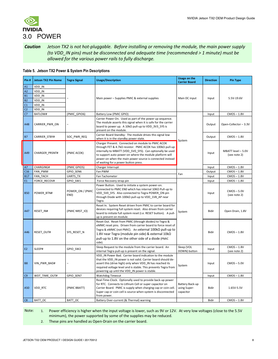
Table 5. Jetson TX2 Power & System Pin Descriptions
Pin #
Jetson TX2 Pin Name
Tegra Signal
Usage/Description
Usage on the
Carrier Board
Direction
Pin Type
−
Main power – Supplies PMIC & external supplies
Main DC input
Input
5.5V-19.6V
A1
A2
B1
B2
C1
C2
C7
VDD_IN
VDD_IN
VDD_IN
VDD_IN
VDD_IN
VDD_IN
BATLOW#
(PMIC_GPIO6)
A48
CARRIER_PWR_ON
−
B7
CARRIER_STBY#
SOC_PWR_REQ
A49
CHARGER_PRSNT#
(PMIC ACOK)
A7
C16
B17
E1
CHARGING#
FAN_PWM
FAN_TACH
FORCE_RECOV#
(PMIC GPIO5)
GPIO_SEN6
UART5_TX
GPIO_SW1
B50
POWER_BTN#
POWER_ON / (PMIC
EN0)
A47
RESET_IN#
(PMIC NRST_IO)
A46
RESET_OUT#
SYS_RESET_N
E2
SLEEP#
GPIO_SW2
B8
VIN_PWR_BAD#
−
C9
WDT_TIME_OUT#
GPIO_SEN7
A50
VDD_RTC
(PMIC BBATT)
C8
BATT_OC
BATT_OC
Battery Low (PMIC GPIO)
Carrier Power On. Used as part of the power up sequence.
The module asserts this signal when it is safe for the carrier
board to power up. A 10kΩ pull-up to VDD_3V3_SYS is
present on the module.
Carrier Board Standby: The module drives this signal low
when it is in the standby power state.
Charger Present. Connected on module to PMIC ACOK
through FET & 4.7kΩ resistor. PMIC ACOK has 100kΩ pull-up
internally to MBATT (VDD_5V0_SYS). Can optionally be used
to support auto-power-on where the module platform will
power-on when the main power source is connected instead
of waiting for a power button press.
Charger Interrupt
Fan PWM
Fan Tachometer
Force Recovery strap pin
Power Button. Used to initiate a system power-on.
Connected to PMIC EN0 which has internal 10KΩ Pull-up to
VDD_5V0_SYS. Also connected to Tegra POWER_ON pin
through Diode with 100kΩ pull-up to VDD_1V8_AP near
Tegra.
Reset In. System Reset driven from PMIC to carrier board for
devices requiring full system reset. Also driven from carrier
board to initiate full system reset (i.e. RESET button). A pull-
up is present on module.
Reset Out. Reset from PMIC (through diodes) to Tegra &
eMMC reset pins. Driven from carrier board to force reset of
Tegra & eMMC (not PMIC). An external 100kΩ pull-up to
1.8V near Tegra (module pin side) & external 10kΩ
pull-up to 1.8V on the other side of a diode (PMIC
side).
Sleep Request to the module from the carrier board. An
internal Tegra pull-up is present on the signal.
VDD_IN Power Bad. Carrier board indication to the module
that the VDD_IN power is not valid. Carrier board should de-
assert this (drive high) only when VDD_IN has reached its
required voltage level and is stable. This prevents Tegra from
powering up until the VDD_IN power is stable.
Watchdog Timeout
Real-Time-Clock. Optionally used to provide back-up power
for RTC. Connects to Lithium Cell or super capacitor on
Carrier Board. PMIC is supply when charging cap or coin cell.
Super cap or coin cell is source when system is disconnected
from power.
Battery Over-current (& Thermal) warning
Input
CMOS – 1.8V
Output
Open-Collector – 3.3V
System
Output
CMOS – 1.8V
Fan
Input
MBATT level – 5.0V
(see note 2)
Input
Output
Input
Input
Input
CMOS – 1.8V
CMOS – 1.8V
CMOS – 1.8V
CMOS – 1.8V
CMOS – 5.0V
(see note 2)
System
Bidir
Open Drain, 1.8V
Bidir
CMOS – 1.8V
Sleep (VOL
DOWN) button
Input
CMOS – 1.8V
(see note 2)
System
Input
CMOS – 5.0V
Input
CMOS – 1.8V
Bidir
1.65V-5.5V
Battery Back-up
using Super-
capacitor
Bidir
CMOS – 1.8V
Note:
1.
2.
Power efficiency is higher when the input voltage is lower, such as 9V or 12V. At very low voltages (close to the 5.5V
minimum), the power supported by some of the supplies may be reduced.
These pins are handled as Open-Drain on the carrier board.
JETSON TX2 OEM PRODUCT | DESIGN GUIDE | 20170912
8
�



 2023年江西萍乡中考道德与法治真题及答案.doc
 2012年重庆南川中考生物真题及答案.doc
 2013年江西师范大学地理学综合及文艺理论基础考研真题.doc
 2020年四川甘孜小升初语文真题及答案I卷.doc
 2020年注册岩土工程师专业基础考试真题及答案.doc
 2023-2024学年福建省厦门市九年级上学期数学月考试题及答案.doc
 2021-2022学年辽宁省沈阳市大东区九年级上学期语文期末试题及答案.doc
 2022-2023学年北京东城区初三第一学期物理期末试卷及答案.doc
 2018上半年江西教师资格初中地理学科知识与教学能力真题及答案.doc
 2012年河北国家公务员申论考试真题及答案-省级.doc
 2020-2021学年江苏省扬州市江都区邵樊片九年级上学期数学第一次质量检测试题及答案.doc
 2022下半年黑龙江教师资格证中学综合素质真题及答案.doc