FT2201
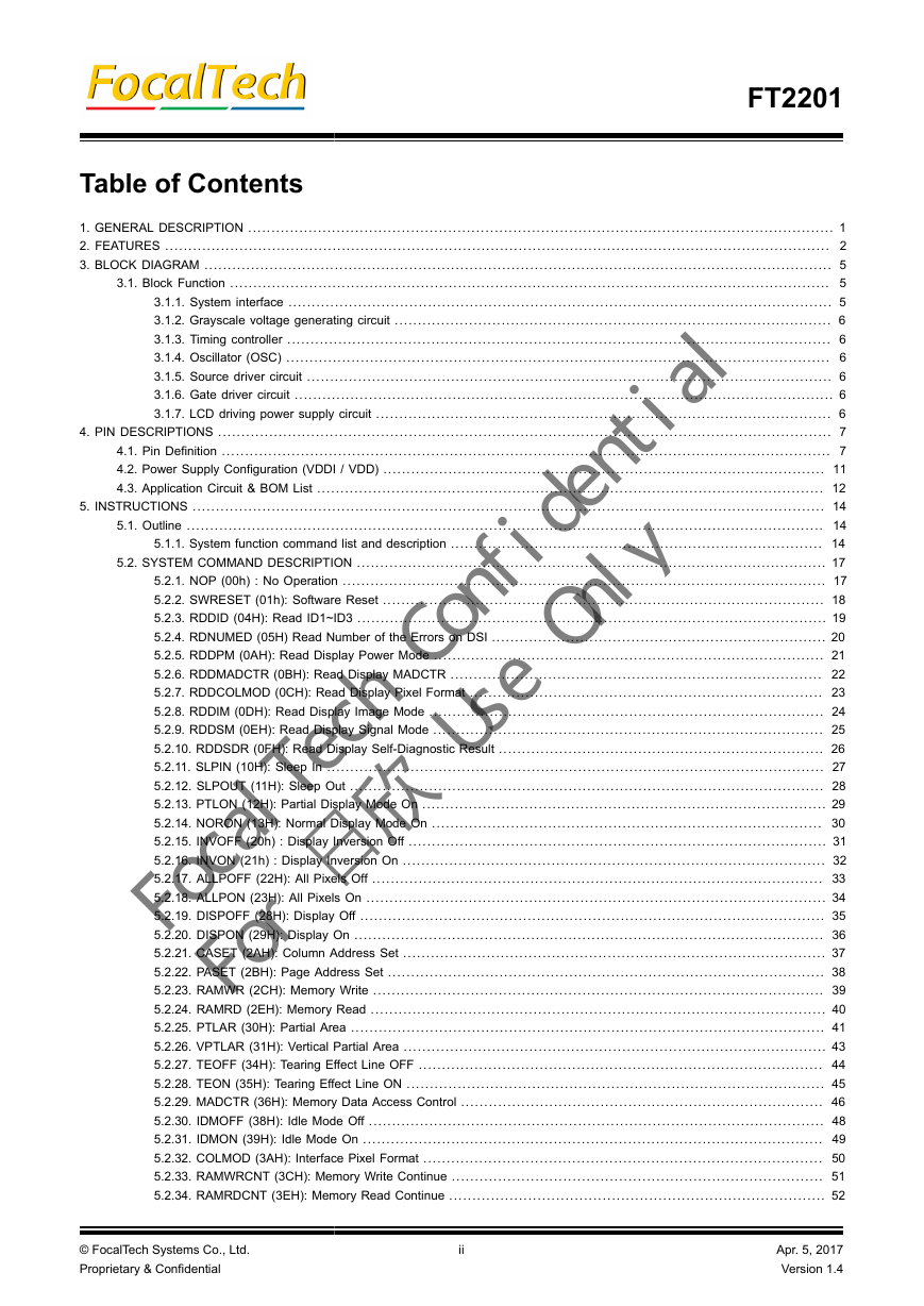
Table of Contents
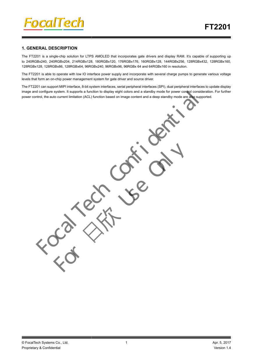
1. GENERAL DESCRIPTION
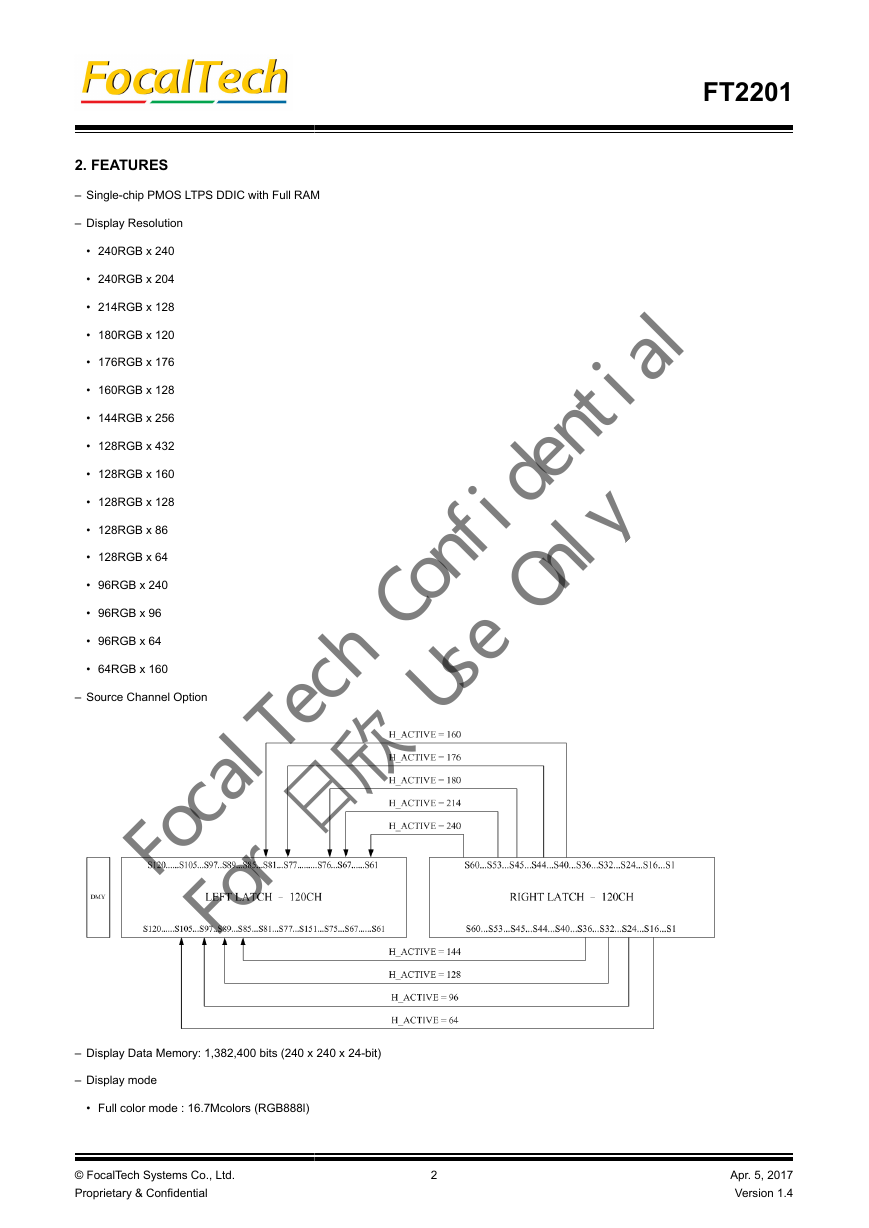
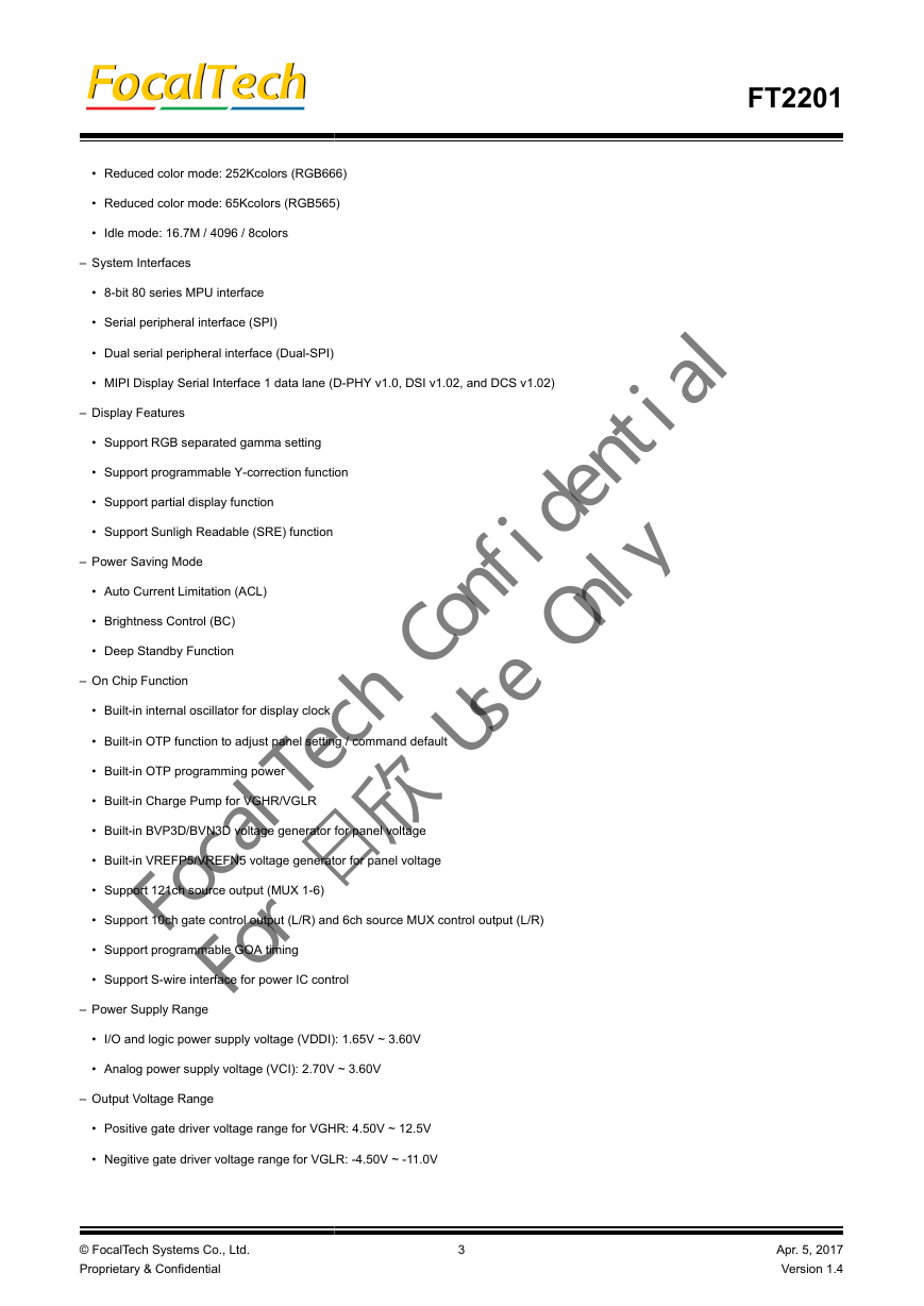
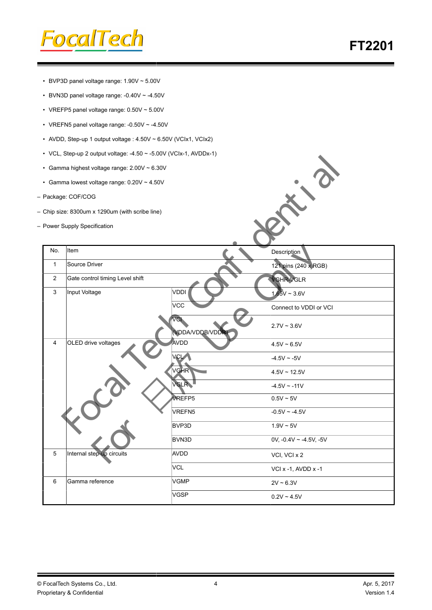
2. FEATURES
3. BLOCK DIAGRAM
3.1. Block Function
3.1.1. System interface
3.1.2. Grayscale voltage generating circuit
3.1.3. Timing controller
3.1.4. Oscillator (OSC)
3.1.5. Source driver circuit
3.1.6. Gate driver circuit
3.1.7. LCD driving power supply circuit
4. PIN DESCRIPTIONS
4.1. Pin Definition
4.2. Power Supply Configuration (VDDI / VDD)
4.3. Application Circuit & BOM List
5. INSTRUCTIONS
5.1. Outline
5.1.1. System function command list and description
5.2. SYSTEM COMMAND DESCRIPTION
5.2.1. NOP (00h) : No Operation
5.2.2. SWRESET (01h): Software Reset
5.2.3. RDDID (04H): Read ID1~ID3
5.2.4. RDNUMED (05H) Read Number of the Errors on DSI
5.2.5. RDDPM (0AH): Read Display Power Mode
5.2.6. RDDMADCTR (0BH): Read Display MADCTR
5.2.7. RDDCOLMOD (0CH): Read Display Pixel Format
5.2.8. RDDIM (0DH): Read Display Image Mode
5.2.9. RDDSM (0EH): Read Display Signal Mode
5.2.10. RDDSDR (0FH): Read Display Self-Diagnostic Result
5.2.11. SLPIN (10H): Sleep In
5.2.12. SLPOUT (11H): Sleep Out
5.2.13. PTLON (12H): Partial Display Mode On
5.2.14. NORON (13H): Normal Display Mode On
5.2.15. INVOFF (20h) : Display Inversion Off
5.2.16. INVON (21h) : Display Inversion On
5.2.17. ALLPOFF (22H): All Pixels Off
5.2.18. ALLPON (23H): All Pixels On
5.2.19. DISPOFF (28H): Display Off
5.2.20. DISPON (29H): Display On
5.2.21. CASET (2AH): Column Address Set
5.2.22. PASET (2BH): Page Address Set
5.2.23. RAMWR (2CH): Memory Write
5.2.24. RAMRD (2EH): Memory Read
5.2.25. PTLAR (30H): Partial Area
5.2.26. VPTLAR (31H): Vertical Partial Area
5.2.27. TEOFF (34H): Tearing Effect Line OFF
5.2.28. TEON (35H): Tearing Effect Line ON
5.2.29. MADCTR (36H): Memory Data Access Control
5.2.30. IDMOFF (38H): Idle Mode Off
5.2.31. IDMON (39H): Idle Mode On
5.2.32. COLMOD (3AH): Interface Pixel Format
5.2.33. RAMWRCNT (3CH): Memory Write Continue
5.2.34. RAMRDCNT (3EH): Memory Read Continue
5.2.35. WRTESCN (44H): Write TE Scan Line
5.2.36. RDSCNL (45H): Read Scan Line
5.2.37. DSTBON (4FH): Deep Standby Mode On
5.2.38. WRSTEW (50H) Write STE Width
5.2.39. WRDBVC (51H) Write Display Brightness Value Control
5.2.40. RDDBVC (52H) Read Display Brightness Value Control
5.2.41. WRACL (55H) Write Auto Current Limitation
5.2.42. RDACL (56H) Read Auto Current Limitation
5.2.43. RDSTEW (60H) Read STE Width
5.2.44. FCC_WRSRE (92H) Focal CleverColor - Write SRE
5.2.45. FCC_RDSRE (93H) Focal CleverColor - Read SRE
5.2.46. RDDDBSTR (A1H): Read DDB Start
5.2.47. RDDDBCNT (A8H): Read DDB Continue
5.2.48. RDFCRC (AAH): Read First CRC
5.2.49. RDCCRC (AFH): Read Continue CRC
5.2.50. RDID1 (DAH): Read ID1
5.2.51. RDID2 (DBH): Read ID2
5.2.52. RDID3 (DCH): Read ID3
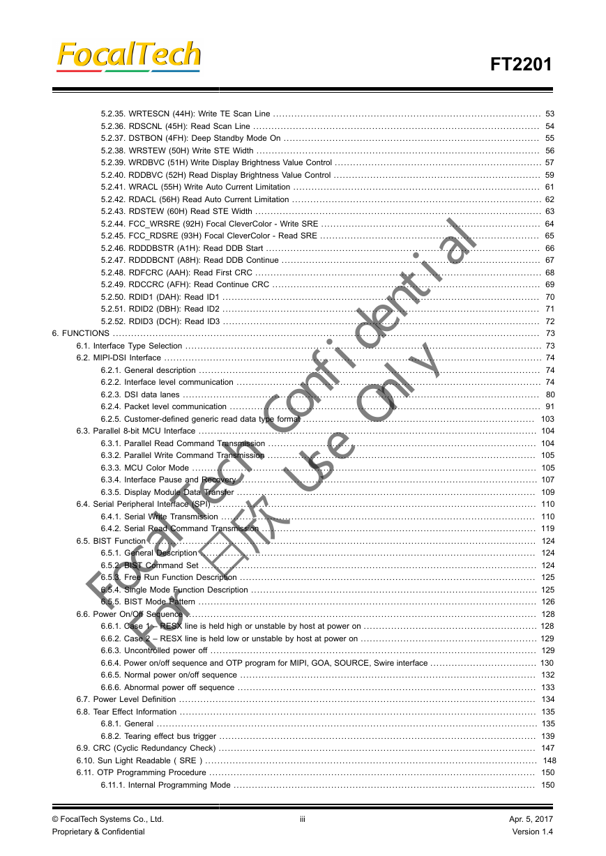
6. FUNCTIONS
6.1. Interface Type Selection
6.2. MIPI-DSI Interface
6.2.1. General description
6.2.2. Interface level communication
6.2.2.1. General
6.2.2.2. DSI-CLK lanes
6.2.3. DSI data lanes
6.2.3.1. General
6.2.3.2. Escape modes
6.2.3.3. High-Speed Data Transmission (HSDT)
6.2.3.4. Bus Turnaround (BTA)
6.2.3.5. Two Data-lane High Speed Transmission
6.2.3.6. Three data-lane high speed transmission
6.2.4. Packet level communication
6.2.4.1. Short Packet (SPa) and Long Packet (LPa) structures
6.2.4.2. Packet transmissions
6.2.5. Customer-defined generic read data type format
6.3. Parallel 8-bit MCU Interface
6.3.1. Parallel Read Command Transmission
6.3.2. Parallel Write Command Transmission
6.3.3. MCU Color Mode
6.3.4. Interface Pause and Recovery
6.3.5. Display Module Data Transfer
6.3.5.1. Method 1
6.3.5.2. Method 2
6.4. Serial Peripheral Interface (SPI)
6.4.1. Serial Write Transmission
6.4.1.1. Type1 Write Transmission (SPI3 single data wire with 9-bit packet)
6.4.1.2. Type2 Write Transmission (SPI4 single data wire with 8-bit packet)
6.4.1.3. Type3 Write Transmission (SPI16 single data wire with 16-bit packet)
6.4.1.4. Type4 Write Transmission (SPI3 dual data wire with 9-bit command packet)
6.4.1.5. Type5 Write Transmission (SPI4 dual data wire with 8-bit command packet)
6.4.2. Serial Read Command Transmission
6.4.2.1. Type1 Read Transmission
6.4.2.2. Type2 Read Transmission
6.4.2.3. Type3 Read Transmission
6.4.2.4. Type4 Read Transmission
6.4.2.5. Type5 Read Transmission
6.5. BIST Function
6.5.1. General Description
6.5.2. BIST Command Set
6.5.3. Free Run Function Description
6.5.4. Single Mode Function Description
6.5.5. BIST Mode Pattern
6.6. Power On/Off Sequence
6.6.1. Case 1 – RESX line is held high or unstable by host at power on
6.6.2. Case 2 – RESX line is held low or unstable by host at power on
6.6.3. Uncontrolled power off
6.6.4. Power on/off sequence and OTP program for MIPI, GOA, SOURCE, Swire interface
6.6.5. Normal power on/off sequence
6.6.6. Abnormal power off sequence
6.7. Power Level Definition
6.8. Tear Effect Information
6.8.1. General
6.8.1.1. Tearing effect line models
6.8.1.2. Tearing effect line timing
6.8.1.3. Example 1 MCU write is faster then panel read
6.8.1.4. Example 1 MCU write is slower then panel read
6.8.2. Tearing effect bus trigger
6.8.2.1. Tearing effect bus trigger enable
6.8.2.2. Tearing effect bus trigger disable
6.8.2.3. Tearing effect bus trigger sequencesTearing effect bus trigger enable sequence – DCSW-L and HSDT
6.8.2.4. Tearing effect bus trigger enable sequence – DCSW-L and LPDT
6.8.2.5. Tearing effect bus trigger enable sequence – DCSW1-S and HPDT
6.8.2.6. Tearing effect bus trigger enable sequence – DCSW1-S and LPDT
6.8.2.7. Tearing effect bus trigger enable sequence – DCSWN-S and HPDT
6.8.2.8. Tearing effect bus trigger enable sequence – DCSWN-S and LPDT
6.9. CRC (Cyclic Redundancy Check)
6.10. Sun Light Readable ( SRE )
6.11. OTP Programming Procedure
6.11.1. Internal Programming Mode
6.11.1.1. Programming flow chart
6.11.1.2. Programming Sequence
6.11.2. External Programming Mode
6.11.2.1. Programming flow chart
6.11.2.2. Programming Sequence
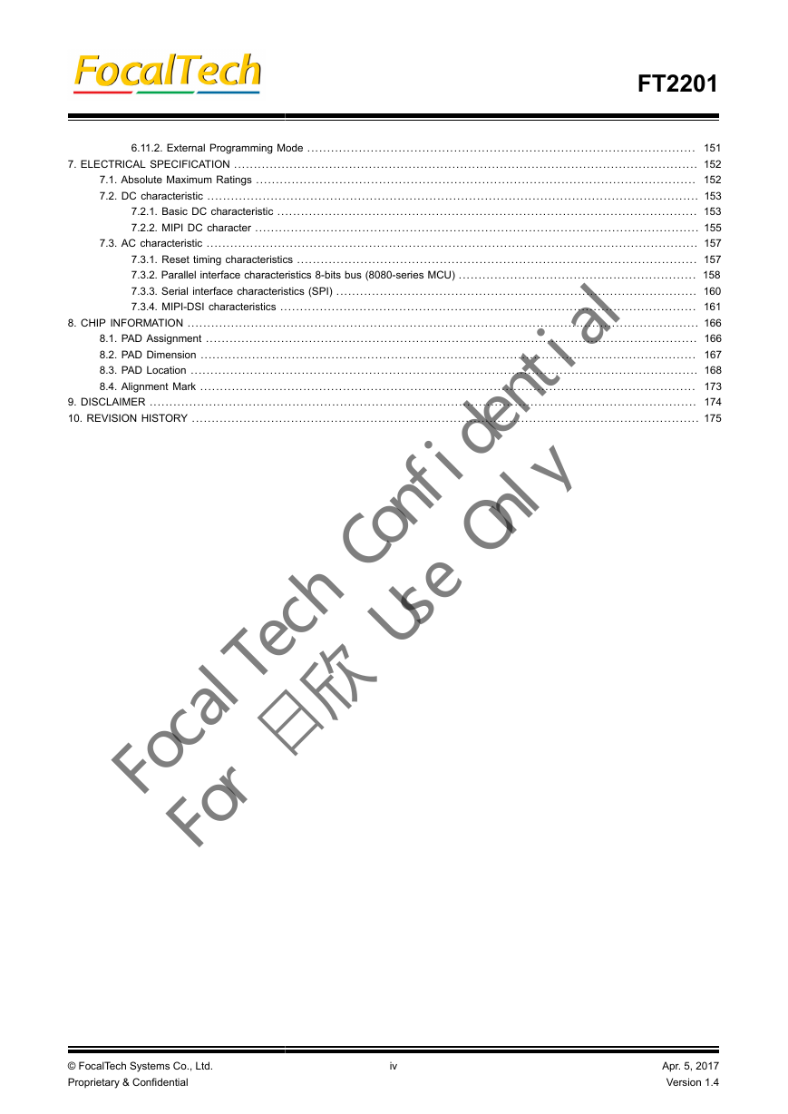
7. ELECTRICAL SPECIFICATION
7.1. Absolute Maximum Ratings
7.2. DC characteristic
7.2.1. Basic DC characteristic
7.2.2. MIPI DC character
7.3. AC characteristic
7.3.1. Reset timing characteristics
7.3.2. Parallel interface characteristics 8-bits bus (8080-series MCU)
7.3.3. Serial interface characteristics (SPI)
7.3.4. MIPI-DSI characteristics
7.3.4.1. High speed mode
7.3.4.2. Low power mode
7.3.4.3. Bursts
7.3.4.4. LP-11 between High Speed and Low Power Modes
8. CHIP INFORMATION
8.1. PAD Assignment
8.2. PAD Dimension
8.3. PAD Location
8.4. Alignment Mark
9. DISCLAIMER
10. REVISION HISTORY


 2023年江西萍乡中考道德与法治真题及答案.doc
 2012年重庆南川中考生物真题及答案.doc
 2013年江西师范大学地理学综合及文艺理论基础考研真题.doc
 2020年四川甘孜小升初语文真题及答案I卷.doc
 2020年注册岩土工程师专业基础考试真题及答案.doc
 2023-2024学年福建省厦门市九年级上学期数学月考试题及答案.doc
 2021-2022学年辽宁省沈阳市大东区九年级上学期语文期末试题及答案.doc
 2022-2023学年北京东城区初三第一学期物理期末试卷及答案.doc
 2018上半年江西教师资格初中地理学科知识与教学能力真题及答案.doc
 2012年河北国家公务员申论考试真题及答案-省级.doc
 2020-2021学年江苏省扬州市江都区邵樊片九年级上学期数学第一次质量检测试题及答案.doc
 2022下半年黑龙江教师资格证中学综合素质真题及答案.doc