Transportation Systems
MVB Interface
Module Description
MVB PC/104
(Hardware)
Order Numbers:
S25659-B2231-A140-*,
-A150-*, A160-*
Version 1.4
Date:
No. of pages:
07.07.2004
49
Transmittal, reproduction, dissemination and/or editing of this document as well as utilization of its contents and
communication thereof to others without express authorization are prohibited. Offenders will be held liable for payment of
damages. All rights created by patent grant or registration of a utility model or design patent are reserved.
© Siemens AG 2004. All Rights Reserved.
�
Name
Schmitt
Tucker
Schmitt
07.07.2004
Dept.
Date
Signed
TS GT E2
14.10.2003
TS RA PH RD 12 15.10.2003
TS GT E2
25.10.2003
signed Schmitt
signed Tucker
signed Schmitt
edited by
checked by
released by
Revision history:
Version
Description of changes
Date
Name
1.0
1.1
Initial creation of the description
05.01.01
Tucker
Modification to ‘5 Technical Data’ Table (addition of
note to Maximum Current
02.04.01
Tucker
Modification to Section 3
1.2
Section 3.1 - PC104 variants A42, A52 and A82 added
12.04.02
Tucker
Section ‘5 D-Type Connector Mounting Bolt’ added
Section 6 - addition of MTBF
Section ‘8.2.1 Wire Wrap Connections General’,
added
Section 12 – Additional references added
Section 13.2 - Additional questions added
Section ‘13.3.3 Wire Wrap Connections’, added
1.3
1.4
Expansion to ‘6 Technical Data’ Table
14.10.03
Schmitt
Modification to ‘2 Order Numbers’
07.07.04
Schmitt
Expansion to ‘6 Technical Data’
MVB PC/104
© Siemens AG 2004. All Rights Reserved.
Version 1.4
Page 2 of 49
�
07.07.2004
WARNING
Hazardous voltages are present in certain parts of this electrical equipment
during operation.
Non-observance of the safety instructions can result in severe personal injury
or damage to property.
Only qualified personnel should work on or around this equipment after
becoming thoroughly familiar with all warnings, safety notices, and
maintenance procedures contained in this manual.
Successful and safe operation of this equipment is dependent on proper
transport, storage, installation, operation and maintenance.
Disclaimer
Siemens AG reserves the right to makes changes to the products herein to improve
reliability, functionality or design. The information in this document and the products
described by this document are subject to change without prior notice.
MVB PC/104
© Siemens AG 2004. All Rights Reserved.
Version 1.4
Page 3 of 49
�
07.07.2004
Table of Contents
1
SHORT DESCRIPTION........................................................................................................................ 5
2 ORDER NUMBERS, VALIDITY OF THE DESCRIPTION............................................................. 6
3 COMPATIBILITY TO S25659-B1231-A*........................................................................................... 7
PART NUMBERS ................................................................................................................................ 7
FUNCTIONALITY................................................................................................................................ 7
EMC................................................................................................................................................. 7
SIDE VIEW............................................................................................................................................. 8
3.1
3.2
3.3
4
5 D-TYPE CONNECTOR MOUNTING BOLTS................................................................................. 11
6
7
TECHNICAL DATA............................................................................................................................ 12
BLOCK DIAGRAM............................................................................................................................. 13
8.1
8.2
8 HARDWARE DESCRIPTION............................................................................................................ 14
BASIC MODES.................................................................................................................................. 14
INTERFACES .................................................................................................................................... 15
8.2.1 Wire Wrap Connections General............................................................................................... 15
8.2.2 Configuration using Wire Wrap-Pins........................................................................................ 15
8.2.3 Electrical interfaces................................................................................................................... 23
EXCHANGE OF PROCESS DATA VIA THE TRAFFIC MEMORY............................................................... 29
8.3.1 Class 1.0 .................................................................................................................................... 30
8.3.2 Classes 1.x and 2 ....................................................................................................................... 31
REQUESTS TO THE HOST .................................................................................................................. 31
TIMING............................................................................................................................................ 35
PRINCIPALS OF SHIELDING AND GROUND ....................................................................................... 35
SOFTWARE DESCRIPTION............................................................................................................. 36
DRIVERS AND API........................................................................................................................... 36
CONFIGURATION OF THE MVBCS1 AND TM.................................................................................. 37
UTILITIES........................................................................................................................................ 37
10.1 ACCESSORIES.................................................................................................................................. 37
10.2
TEST OPTIONS ................................................................................................................................. 37
LIST OF ABBREVIATIONS.......................................................................................................... 38
8.4
8.5
8.6
9.1
9.2
8.3
9
10
11
12
REFERENCES ................................................................................................................................. 39
13
APPENDIX ....................................................................................................................................... 39
13.1
TIMING CHARTS .............................................................................................................................. 40
13.2 CHECK LIST..................................................................................................................................... 44
13.3 WIRE-WRAP TOOLS........................................................................................................................ 47
Electric Tool.......................................................................................................................... 47
Hand Tool.............................................................................................................................. 48
13.4 WIRE WRAP CONNECTIONS ............................................................................................................ 49
13.3.1
13.3.2
MVB PC/104
© Siemens AG 2004. All Rights Reserved.
Version 1.4
Page 4 of 49
�
07.07.2004
1 Short Description
The MVB PC/104 is an interface module with which it is possible to connect electronic
controllers to the MVB. In this description a distinction is made between the following
classes or groups of classes:
• Class 1.0
• Class 1.1, 1.2 and 1.3
• Class 2
In the descriptions it is important to note differences between devices of Class 1.0, Class
1.x (x=1…3) and Class 2. Where Class 1.0 devices behave differently from Class 1.x or
Class 2 devices, the description has a gray background like this paragraph.
The user of the MVB PC/104 module is provided with API software for their development
for the use of the module in Class 1.1, 1.2 and 1.3 (see [API1] and [API2]). The scope of
service of this API software is larger the higher the class. The following overview describes
the current definition of the individual classes. The increase in functionality of each class
over the previous class is described.
Class 1.0:
• MVBCS1 is preconfigured (Class 1 Mode, see [MVBCS1])
• No API software
• The quantity and type of ports are predefined (see [MVBCS1])
• Fixed assignment between the device address and the port numbers
• No sink-time supervision
Class 1.1 (in addition to or instead of the functionality of Class 1.0):
• MVBCS1 works in Class 2/3/4 Mode, see [MVBCS1]
• MVBCS1 can be configured with API software provided
• The quantity, type and port-numbers can be configured
• Sink-time supervision is available
• Functions of the API software:
Initialize MVBCS1
Start MVBCS1
Stop MVBCS1
Read complete port
Write complete port
In Class 1.2 (in addition to the functionality of Class 1.1):
Functions of the API software:
Read individual variables from a port
Write individual variables to a port
Assign symbolic name to a variable
Management of static configuration data (NSDB)
MVB PC/104
© Siemens AG 2004. All Rights Reserved.
Version 1.4
Page 5 of 49
�
07.07.2004
In Class 1.3 (in addition to the functionality of Class 1.2):
• Dynamic management (recharging) of configuration data (NSDB).
This functionality has to be provided by the user because it is host system specific
In Class 2 (in addition to the functionality of Class 1.3):
• Exchange of message data (the API software is replaced by MVB drivers).
Comment: for SIEMENS Transportation Systems the module is used in Class 2, for
example, in the TCN 6U Gateway and in the AS 318 MVB.
The MVB PC/104 card is mechanically and electrically designed in accordance with
PC/104 specification Version 2.1 [PC104]. You will find detailed information about this
standard in the Internet [WWW104].
2 Order Numbers, Validity of the Description
The order numbers of the MVB PC/104 module are:
Order numbers
S25659-B2231-A140-*
A2V 1085938 Supplier 680550
S25659-B2231-A150-*
A2V 1099641 Supplier 680550
S25659-B2231-A160-*
A2V 1093619 Supplier 680550
Submin. D9 Connectors
female
connectors
Traffic memory
J1(X11), J2(X12),
J3(X13)
right-angled Available
Available
straight
Available
Available
right-angled not available
Available
This description is valid for the following MVB PC/104 modules:
S25659-B2231-A140-* (* ≥ 3)
S25659-B2231-A150-* (* ≥ 2)
S25659-B2231-A160-* (* ≥ 2)
The variants with order numbers S25659-B2231-A130-* or S25659-B2231-A190-* are not
described here. These variants can be operated in Class 1.0 only and for example, the
-A130-* is used in the Siemens MVB-Compact I/O.
MVB PC/104
© Siemens AG 2004. All Rights Reserved.
Version 1.4
Page 6 of 49
�
3 Compatibility to S25659-B1231-A*
07.07.2004
3.1 Part Numbers
The table below shows which S25659-B2231-A* module should be used in place of the old
S25659-B1231-A* module
New Siemens Part Number Old Siemens Part Number
S25659-B2231-A140
S25659-B2231-A150
S25659-B2231-A160
S25659-B1231-A4
S25659-B1231-A41
S25659-B1231-A42
S25659-B1231-A7
S25659-B1231-A5
S25659-B1231-A51
S25659-B1231-A52
S25659-B1231-A8
S25659-B1231-A81
S25659-B1231-A82
S25659-B1231-A6
S25659-B1231-A65
3.2 Functionality
All tests carried out show that the data of the old devices are so close to the new ones, that
these differences can be neglected.
A definition of a ,Start-Up` Time has been added in order to ensure correct access to the
new types of the MVB PC/104 card after Reset:
The host must wait 1.5ms after Reset is driven inactive before it can make any form
of access to the MVB PC/104 card; otherwise it will read or write invalid data.
The worst case values of power consumption of the board has been reduced (addition of
note to Maximum Current in chapter 6).
3.3 EMC
All test carried out by our specialists show that the data of the old devices are so close to
the new ones, that these differences can be neglected.
We herewith confirm that the qualification tests carried out on with old MVB-cards is
interchangeable with the new type of MVB-card.
Concerning the EMC-tests, the new type of MVB-cards were tested in the same test
environment in which the old type of MVB-cards were qualified.
The result was that the new types showed better or identical values as the old types.
Therefore, if the test "Teiltypprüfung MVB Kommunikation" was passed successfully with a
previous issue of a PC/104 card it is not necessary to repeat this test.
MVB PC/104
© Siemens AG 2004. All Rights Reserved.
Version 1.4
Page 7 of 49
�
4 Side View
07.07.2004
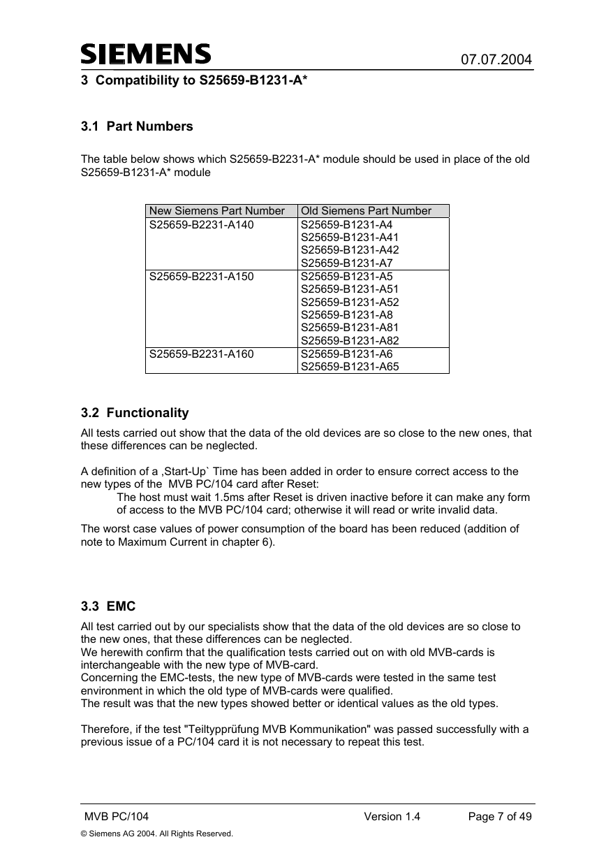
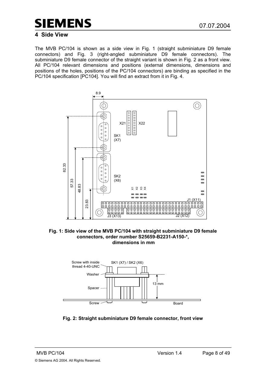
The MVB PC/104 is shown as a side view in Fig. 1 (straight subminiature D9 female
connectors) and Fig. 3
female connectors). The
subminiature D9 female connector of the straight variant is shown in Fig. 2 as a front view.
All PC/104 relevant dimensions and positions (external dimensions, dimensions and
positions of the holes, positions of the PC/104 connectors) are binding as specified in the
PC/104 specification [PC104]. You will find an extract from it in Fig. 4.
(right-angled subminiature D9
8.9
X21
X22
SK1
(X7)
SK2
(X6)
J3 (X13)
3
3
.
2
8
3
3
.
7
5
3
8
.
8
4
3
8
.
3
2
1
X
2
X
3
X
4
X
J1 (X11)
J2 (X12)
Fig. 1: Side view of the MVB PC/104 with straight subminiature D9 female
connectors, order number S25659-B2231-A150-*,
dimensions in mm
Screw with inside
thread 4-40-UNC
SK1 (X7) / SK2 (X6)
Washer
Spacer
Screw
13 mm
Board
Fig. 2: Straight subminiature D9 female connector, front view
MVB PC/104
© Siemens AG 2004. All Rights Reserved.
Version 1.4
Page 8 of 49
�


 2023年江西萍乡中考道德与法治真题及答案.doc
 2012年重庆南川中考生物真题及答案.doc
 2013年江西师范大学地理学综合及文艺理论基础考研真题.doc
 2020年四川甘孜小升初语文真题及答案I卷.doc
 2020年注册岩土工程师专业基础考试真题及答案.doc
 2023-2024学年福建省厦门市九年级上学期数学月考试题及答案.doc
 2021-2022学年辽宁省沈阳市大东区九年级上学期语文期末试题及答案.doc
 2022-2023学年北京东城区初三第一学期物理期末试卷及答案.doc
 2018上半年江西教师资格初中地理学科知识与教学能力真题及答案.doc
 2012年河北国家公务员申论考试真题及答案-省级.doc
 2020-2021学年江苏省扬州市江都区邵樊片九年级上学期数学第一次质量检测试题及答案.doc
 2022下半年黑龙江教师资格证中学综合素质真题及答案.doc