Customer Training Material
Workshop 2.1
ANSYS AQWA
Hydrodynamic
Diffraction
Introduction to ANSYS
AQWA
ANSYS, Inc. Proprietary
© 2012 ANSYS, Inc. All rights reserved.
WS2.1-1
Release 14.0
January 2012
�
Workshop 2.1 – ANSYS AQWA Hydrodynamic Diffraction
The AQWA Simulation Process
Customer Training Material
CAD
DesignModeler
Hydrodynamic
Diffraction
ANSYS, Inc. Proprietary
© 2012 ANSYS, Inc. All rights reserved.
WS2.1-2
Release 14.0
January 2012
�
Workshop 2.1 – ANSYS AQWA Hydrodynamic Diffraction
Creating geometry ready for import to WB HD
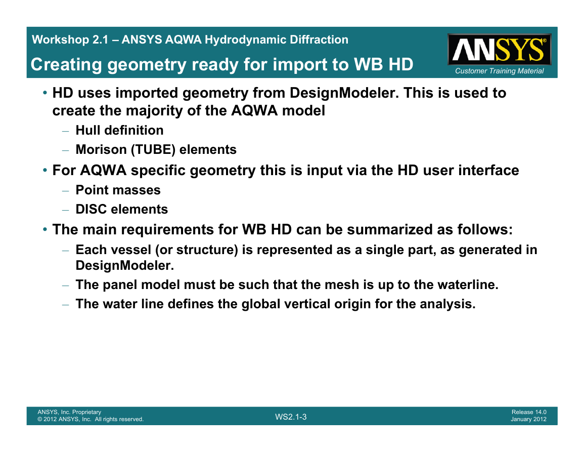
• HD uses imported geometry from DesignModeler. This is used to
create the majority of the AQWA model
– Hull definition
– Morison (TUBE) elements
Customer Training Material
• For AQWA specific geometry this is input via the HD user interface
– Point masses
– DISC elements
• The main requirements for WB HD can be summarized as follows:
– Each vessel (or structure) is represented as a single part, as generated in
DesignModeler.
– The panel model must be such that the mesh is up to the waterline.
– The water line defines the global vertical origin for the analysis.
ANSYS, Inc. Proprietary
© 2012 ANSYS, Inc. All rights reserved.
WS2.1-3
Release 14.0
January 2012
�
Customer Training Material
Workshop 2.1 – ANSYS AQWA Hydrodynamic Diffraction
Vessel/Structure definition
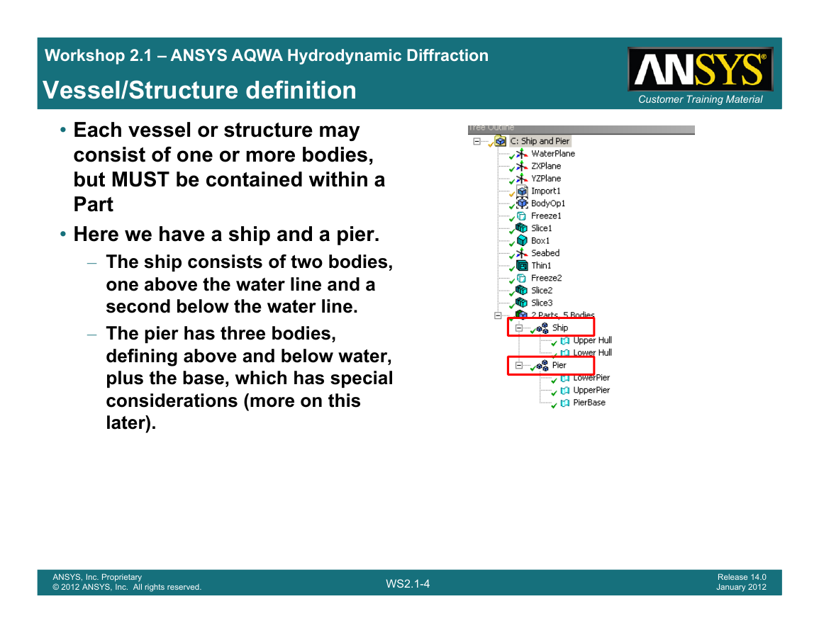
• Each vessel or structure may
consist of one or more bodies,
but MUST be contained within a
Part
• Here we have a ship and a pier.
– The ship consists of two bodies,
one above the water line and a
second below the water line.
– The pier has three bodies,
defining above and below water,
plus the base, which has special
considerations (more on this
later).
ANSYS, Inc. Proprietary
© 2012 ANSYS, Inc. All rights reserved.
WS2.1-4
Release 14.0
January 2012
�
Workshop 2.1 – ANSYS AQWA Hydrodynamic Diffraction
Global axis system in AQWAWB
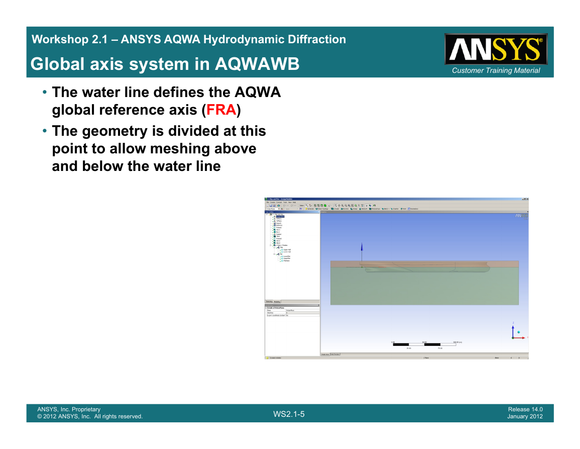
• The water line defines the AQWA
global reference axis (FRA)
• The geometry is divided at this
point to allow meshing above
and below the water line
Customer Training Material
ANSYS, Inc. Proprietary
© 2012 ANSYS, Inc. All rights reserved.
WS2.1-5
Release 14.0
January 2012
�
Workshop 2.1 – ANSYS AQWA Hydrodynamic Diffraction
Radiation/Diffraction Analysis Stages
• WB HD for the diffraction analysis consists of five stages
Customer Training Material
– Insert HD system and associate geometry
– Add AQWA specific parameters
– Add AQWA specific elements
– Mesh
– Analysis and post-processing
ANSYS, Inc. Proprietary
© 2012 ANSYS, Inc. All rights reserved.
WS2.1-6
Release 14.0
January 2012
�
Workshop 2.1 – ANSYS AQWA Hydrodynamic Diffraction
Worked Exercises
• Three models are going to be considered
Customer Training Material
– Single ship
– Two ships demonstrating hydrodynamic interaction
– One ship and a pier demonstrating specific requirements of including a
fixed structure in the analysis
ANSYS, Inc. Proprietary
© 2012 ANSYS, Inc. All rights reserved.
WS2.1-7
Release 14.0
January 2012
�
Workshop 2.1 – ANSYS AQWA Hydrodynamic Diffraction
Insert HD System and associate geometry
• Create HD System (as shown in Lecture 1)
• Import CAD geometry and/or create model directly
• Repair as necessary
• Position the model(s) in the correct vertical and horizontal locations
required for the analysis
• Cut the model(s) at the water line to provide the required delineation
between above and below water (no element splitting)
• Combine bodies associated with a single vessel to form one part.
Customer Training Material
ANSYS, Inc. Proprietary
© 2012 ANSYS, Inc. All rights reserved.
WS2.1-8
Release 14.0
January 2012
�



 2023年江西萍乡中考道德与法治真题及答案.doc
 2012年重庆南川中考生物真题及答案.doc
 2013年江西师范大学地理学综合及文艺理论基础考研真题.doc
 2020年四川甘孜小升初语文真题及答案I卷.doc
 2020年注册岩土工程师专业基础考试真题及答案.doc
 2023-2024学年福建省厦门市九年级上学期数学月考试题及答案.doc
 2021-2022学年辽宁省沈阳市大东区九年级上学期语文期末试题及答案.doc
 2022-2023学年北京东城区初三第一学期物理期末试卷及答案.doc
 2018上半年江西教师资格初中地理学科知识与教学能力真题及答案.doc
 2012年河北国家公务员申论考试真题及答案-省级.doc
 2020-2021学年江苏省扬州市江都区邵樊片九年级上学期数学第一次质量检测试题及答案.doc
 2022下半年黑龙江教师资格证中学综合素质真题及答案.doc