RTL8153B-VB-CG
INTEGRATED 10/100/1000M ETHERNET
CONTROLLER FOR USB 3.0 APPLICATIONS
DATASHEET
(CONFIDENTIAL: Development Partners Only)
Rev. 1.0
27 January 2016
Track ID: JATR-8275-15
Realtek Semiconductor Corp.
No. 2, Innovation Road II, Hsinchu Science Park, Hsinchu 300, Taiwan
Tel.: +886-3-578-0211. Fax: +886-3-577-6047
www.realtek.com
�
RTL8153B-VB
Datasheet
COPYRIGHT
©2016 Realtek Semiconductor Corp. All rights reserved. No part of this document may be reproduced,
transmitted, transcribed, stored in a retrieval system, or translated into any language in any form or by any
means without the written permission of Realtek Semiconductor Corp.
DISCLAIMER
Realtek provides this document ‘as is’, without warranty of any kind. Realtek may make improvements
and/or changes in this document or in the product described in this document at any time. This document
could include technical inaccuracies or typographical errors.
TRADEMARKS
Realtek is a trademark of Realtek Semiconductor Corporation. Other names mentioned in this document
are trademarks/registered trademarks of their respective owners.
LICENSE
This product is covered by one or more of the following patents: US5,307,459, US5,434,872,
US5,732,094, US6,570,884, US6,115,776, and US6,327,625.
USING THIS DOCUMENT
This document is intended for the software engineer’s reference and provides detailed programming
information.
Though every effort has been made to ensure that this document is current and accurate, more information
may have become available subsequent to the production of this guide.
REVISION HISTORY
Release Date Summary
2016/01/27
First release.
Revision
1.0
Integrated 10/100/1000M Ethernet Controller for USB 3.0 Applications
ii
Track ID: JATR-8275-15 Rev. 1.0
�
Table of Contents
RTL8153B-VB
Datasheet
4.1.
5.
6.
6.1.
1. GENERAL DESCRIPTION..............................................................................................................................................1
FEATURES.........................................................................................................................................................................3
2.
SYSTEM APPLICATIONS...............................................................................................................................................4
3.
4.
PIN ASSIGNMENTS .........................................................................................................................................................4
PACKAGE IDENTIFICATION...........................................................................................................................................4
PIN DESCRIPTIONS.........................................................................................................................................................5
POWER MANAGEMENT PIN ..........................................................................................................................................5
5.1.
SPI (SERIAL PERIPHERAL INTERFACE) FLASH PINS .....................................................................................................5
5.2.
EEPROM PINS ............................................................................................................................................................5
5.3.
TRANSCEIVER INTERFACE PINS....................................................................................................................................6
5.4.
CLOCK PINS .................................................................................................................................................................6
5.5.
REGULATOR AND REFERENCE PINS..............................................................................................................................6
5.6.
LED PINS.....................................................................................................................................................................7
5.7.
5.8.
POWER AND GROUND PINS ..........................................................................................................................................7
GPIO PIN.....................................................................................................................................................................7
5.9.
5.10. USB INTERFACE PINS ..................................................................................................................................................8
SHARED PIN CONFIGURATION......................................................................................................................................8
5.11.
FUNCTIONAL DESCRIPTION.......................................................................................................................................9
USB INTERFACE ..........................................................................................................................................................9
6.1.1. USB Configurations................................................................................................................................................9
6.1.2. Endpoint 0 ..............................................................................................................................................................9
6.1.3. Endpoint 1 Bulk-In .................................................................................................................................................9
6.1.4. Endpoint 2 Bulk-Out...............................................................................................................................................9
6.1.5. Endpoint 3 Interrupt-In ..........................................................................................................................................9
CUSTOMIZABLE LED CONFIGURATION......................................................................................................................10
PHY TRANSCEIVER ...................................................................................................................................................12
6.3.1. PHY Transmitter...................................................................................................................................................12
6.3.2. PHY Receiver .......................................................................................................................................................12
6.3.3. Link-Down Power Saving Mode...........................................................................................................................13
6.3.4. Next Page .............................................................................................................................................................13
EEPROM INTERFACE................................................................................................................................................13
6.4.
SPI (SERIAL PERIPHERAL INTERFACE) FLASH............................................................................................................14
6.5.
POWER MANAGEMENT...............................................................................................................................................14
6.6.
6.7.
LINK POWER MANAGEMENT (LPM) ..........................................................................................................................15
PROTOCOL OFFLOAD .................................................................................................................................................15
6.8.
6.9. WAKE PACKET DETECTION (WPD) ...........................................................................................................................16
6.10.
‘REALWOW!’ (WAKE-ON-WAN) TECHNOLOGY ......................................................................................................16
6.11.
ENERGY EFFICIENT ETHERNET (EEE)........................................................................................................................16
LAN DISABLE MODE.................................................................................................................................................16
6.12.
6.13. ALWAYS ON ALWAYS CONNECTED...........................................................................................................................17
6.14.
SWITCHING REGULATOR............................................................................................................................................17
6.15.
LDO REGULATOR......................................................................................................................................................17
6.16. DRIVER AUTO-INSTALL MODE ..................................................................................................................................18
7. CHARACTERISTICS......................................................................................................................................................19
ABSOLUTE MAXIMUM RATINGS ................................................................................................................................19
RECOMMENDED OPERATING CONDITIONS .................................................................................................................19
CRYSTAL REQUIREMENTS..........................................................................................................................................20
7.1.
7.2.
7.3.
6.2.
6.3.
Integrated 10/100/1000M Ethernet Controller for USB 3.0 Applications
iii
Track ID: JATR-8275-15 Rev. 1.0
�
7.4.
7.5.
7.6.
7.7.
7.8.
RTL8153B-VB
Datasheet
OSCILLATOR REQUIREMENTS ....................................................................................................................................20
ENVIRONMENTAL CHARACTERISTICS ........................................................................................................................21
DC CHARACTERISTICS...............................................................................................................................................21
REFLOW PROFILE RECOMMENDATIONS .....................................................................................................................22
AC CHARACTERISTICS...............................................................................................................................................22
SPI EEPROM Interface Timing............................................................................................................................22
SPI Flash Commands ...........................................................................................................................................23
SPI Flash Interface Timing...................................................................................................................................25
SPI Flash Type Supported....................................................................................................................................26
8. MECHANICAL DIMENSIONS......................................................................................................................................27
9. ORDERING INFORMATION........................................................................................................................................28
7.8.1.
7.8.2.
7.8.3.
7.8.4.
Integrated 10/100/1000M Ethernet Controller for USB 3.0 Applications
iv
Track ID: JATR-8275-15 Rev. 1.0
�
List of Tables
RTL8153B-VB
Datasheet
TABLE 1. POWER MANAGEMENT PIN ...........................................................................................................................................5
TABLE 2. SPI FLASH PINS ............................................................................................................................................................5
TABLE 3. EEPROM PINS .............................................................................................................................................................5
TABLE 4. TRANSCEIVER INTERFACE PINS ....................................................................................................................................6
TABLE 5. CLOCK PINS..................................................................................................................................................................6
TABLE 6. REGULATOR AND REFERENCE PINS ..............................................................................................................................6
TABLE 7. LED PINS......................................................................................................................................................................7
TABLE 8. POWER AND GROUND PINS ...........................................................................................................................................7
TABLE 9. GPIO PIN......................................................................................................................................................................7
TABLE 10. USB INTERFACE PINS ..................................................................................................................................................8
TABLE 11. SHARED PIN MODES.....................................................................................................................................................8
TABLE 12. LED SELECT (OCP REGISTER OFFSET DD90H~DD91H)...........................................................................................10
TABLE 13. CUSTOMIZED LEDS ...................................................................................................................................................10
TABLE 14. FIXED LED MODE .....................................................................................................................................................10
TABLE 15. LED FEATURE CONTROL-1........................................................................................................................................11
TABLE 16. LED FEATURE CONTROL-2........................................................................................................................................11
TABLE 17. LED OPTION 1 & OPTION 2 SETTINGS .......................................................................................................................11
TABLE 18. EEPROM INTERFACE................................................................................................................................................13
TABLE 19. SPI FLASH INTERFACE ...............................................................................................................................................14
TABLE 20. ABSOLUTE MAXIMUM RATINGS ................................................................................................................................19
TABLE 21. RECOMMENDED OPERATING CONDITIONS .................................................................................................................19
TABLE 22. CRYSTAL REQUIREMENTS..........................................................................................................................................20
TABLE 23. OSCILLATOR REQUIREMENTS ....................................................................................................................................20
TABLE 24. ENVIRONMENTAL CHARACTERISTICS ........................................................................................................................21
TABLE 25. DC CHARACTERISTICS...............................................................................................................................................21
TABLE 26. REFLOW PROFILE RECOMMENDATIONS .....................................................................................................................22
TABLE 27. SPI EEPROM ACCESS TIMING PARAMETERS............................................................................................................23
TABLE 28. SPI FLASH COMMANDS..............................................................................................................................................23
TABLE 29. SPI FLASH ACCESS TIMING PARAMETERS .................................................................................................................26
TABLE 30. SPI FLASH TYPES SUPPORTED ...................................................................................................................................26
TABLE 31. ORDERING INFORMATION ..........................................................................................................................................28
List of Figures
FIGURE 1. PIN ASSIGNMENTS.......................................................................................................................................................4
FIGURE 2. SPI EEPROM INTERFACE TIMING ............................................................................................................................22
FIGURE 3. WREN/WRDI COMMAND SEQUENCE.......................................................................................................................23
FIGURE 4. READ COMMAND SEQUENCE.....................................................................................................................................24
FIGURE 5. PAGE PROGRAM COMMAND SEQUENCE ....................................................................................................................24
FIGURE 6. SECTOR/BLOCK ERASE COMMAND SEQUENCE..........................................................................................................24
FIGURE 7. CHIP ERASE COMMAND SEQUENCE...........................................................................................................................25
FIGURE 8. SPI FLASH INTERFACE TIMING..................................................................................................................................25
Integrated 10/100/1000M Ethernet Controller for USB 3.0 Applications
v
Track ID: JATR-8275-15 Rev. 1.0
�
RTL8153B-VB
Datasheet
that can replace
1. General Description
The Realtek RTL8153B-VB-CG 10/100/1000M Ethernet controller combines a triple-speed IEEE 802.3
compliant Media Access Controller (MAC) with a triple-speed Ethernet transceiver, USB 3.0 bus
controller, and embedded memory. With state-of-the-art DSP technology and mixed-mode signal
technology, the RTL8153B-VB offers high-speed transmission over CAT 5 UTP cable or CAT 3 UTP
(10Mbps only) cable. Functions such as Crossover Detection and Auto-Correction, polarity correction,
adaptive equalization, cross-talk cancellation, echo cancellation, timing recovery, and error correction are
implemented to provide robust transmission and reception capabilities. The RTL8153B-VB features
embedded One-Time-Programmable (OTP) memory
the external EEPROM
(93C46/93C56/93C66).
The RTL8153B-VB features USB 3.0 to provide higher bandwidth and improved protocols for data
exchange between the host and the device. USB 3.0 also offers more advanced power management
features for energy saving.
Advanced Configuration Power management Interface (ACPI)—power management for modern
operating systems that are capable of Operating System-directed Power Management (OSPM)—is
supported to achieve the most efficient power management possible. In addition to the ACPI feature,
remote wake-up (including AMD Magic Packet and Microsoft Wake-Up Frame) is supported in both
ACPI and APM (Advanced Power Management) environments.
The RTL8153B-VB supports Microsoft Wake Packet Detection (WPD) to provide Wake-Up Frame
information to the OS, e.g., PatternID, OriginalPacketSize, SavedPacketSize, SavedPacketOffset, etc.
WPD helps prevent unwanted/unauthorized wake-up of a sleeping computer.
The RTL8153B-VB supports ‘RealWoW!’ technology to enable remote wake-up of a sleeping PC
through the Internet. This feature allows PCs to reduce power consumption by remaining in low power
sleeping state until needed.
Note: The ‘RealWoW!’ service requires registration on first time use.
The RTL8153B-VB supports Protocol offload. It offloads some of the most common protocols to NIC
hardware in order to prevent spurious wake-up and further reduce power consumption. The
RTL8153B-VB can offload ARP (IPv4) and NS (IPv6) protocols while in the D3 power saving state.
The RTL8153B-VB supports the ECMA (European Computer Manufacturers Association) proxy for
sleeping hosts standard. The standard specifies maintenance of network connectivity and presence via
proxies in order to extend the sleep duration of higher-powered hosts. It handles some network tasks on
behalf of the host, allowing the host to remain in sleep mode for longer periods. Required and optional
behavior of an operating proxy includes generating reply packets, ignoring packets, and waking the host.
Integrated 10/100/1000M Ethernet Controller for USB 3.0 Applications
1
Track ID: JATR-8275-15 Rev. 1.0
�
RTL8153B-VB
Datasheet
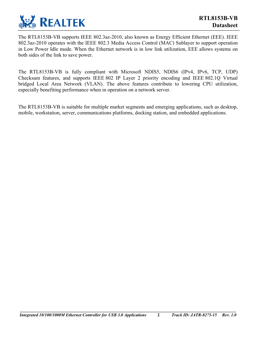
The RTL8153B-VB supports IEEE 802.3az-2010, also known as Energy Efficient Ethernet (EEE). IEEE
802.3az-2010 operates with the IEEE 802.3 Media Access Control (MAC) Sublayer to support operation
in Low Power Idle mode. When the Ethernet network is in low link utilization, EEE allows systems on
both sides of the link to save power.
The RTL8153B-VB is fully compliant with Microsoft NDIS5, NDIS6 (IPv4, IPv6, TCP, UDP)
Checksum features, and supports IEEE 802 IP Layer 2 priority encoding and IEEE 802.1Q Virtual
bridged Local Area Network (VLAN). The above features contribute to lowering CPU utilization,
especially benefiting performance when in operation on a network server.
The RTL8153B-VB is suitable for multiple market segments and emerging applications, such as desktop,
mobile, workstation, server, communications platforms, docking station, and embedded applications.
Integrated 10/100/1000M Ethernet Controller for USB 3.0 Applications
2
Track ID: JATR-8275-15 Rev. 1.0
�
RTL8153B-VB
Datasheet
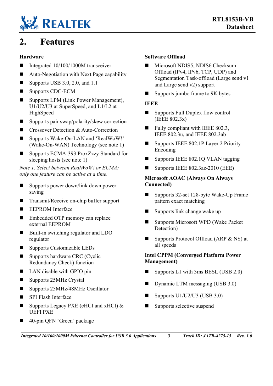
Features
Integrated 10/100/1000M transceiver
2.
Hardware
Auto-Negotiation with Next Page capability
Supports USB 3.0, 2.0, and 1.1
Supports CDC-ECM
Supports LPM (Link Power Management),
U1/U2/U3 at SuperSpeed, and L1/L2 at
HighSpeed
Supports pair swap/polarity/skew correction
Crossover Detection & Auto-Correction
Supports Wake-On-LAN and ‘RealWoW!’
(Wake-On-WAN) Technology (see note 1)
Supports ECMA-393 ProxZzzy Standard for
sleeping hosts (see note 1)
Note 1. Select between RealWoW! or ECMA;
only one feature can be active at a time.
Supports power down/link down power
saving
Transmit/Receive on-chip buffer support
EEPROM Interface
Embedded OTP memory can replace
external EEPROM
Built-in switching regulator and LDO
regulator
Supports Customizable LEDs
Supports hardware CRC (Cyclic
Redundancy Check) function
LAN disable with GPIO pin
Supports 25MHz Crystal
Supports 25MHz/48MHz Oscillator
SPI Flash Interface
Supports Legacy PXE (eHCI and xHCI) &
UEFI PXE
Software Offload
Microsoft NDIS5, NDIS6 Checksum
Offload (IPv4, IPv6, TCP, UDP) and
Segmentation Task-offload (Large send v1
and Large send v2) support
Supports jumbo frame to 9K bytes
IEEE
Supports Full Duplex flow control
(IEEE 802.3x)
Fully compliant with IEEE 802.3,
IEEE 802.3u, and IEEE 802.3ab
Supports IEEE 802.1P Layer 2 Priority
Encoding
Supports IEEE 802.1Q VLAN tagging
Supports IEEE 802.3az-2010 (EEE)
Microsoft AOAC (Always On Always
Connected)
Supports 32-set 128-byte Wake-Up Frame
pattern exact matching
Supports link change wake up
Supports Microsoft WPD (Wake Packet
Detection)
Supports Protocol Offload (ARP & NS) at
all speeds
Intel CPPM (Converged Platform Power
Management)
Supports L1 with 3ms BESL (USB 2.0)
Dynamic LTM messaging (USB 3.0)
Supports U1/U2/U3 (USB 3.0)
Supports selective suspend
40-pin QFN ‘Green’ package
Integrated 10/100/1000M Ethernet Controller for USB 3.0 Applications
3
Track ID: JATR-8275-15 Rev. 1.0
�



 2023年江西萍乡中考道德与法治真题及答案.doc
 2012年重庆南川中考生物真题及答案.doc
 2013年江西师范大学地理学综合及文艺理论基础考研真题.doc
 2020年四川甘孜小升初语文真题及答案I卷.doc
 2020年注册岩土工程师专业基础考试真题及答案.doc
 2023-2024学年福建省厦门市九年级上学期数学月考试题及答案.doc
 2021-2022学年辽宁省沈阳市大东区九年级上学期语文期末试题及答案.doc
 2022-2023学年北京东城区初三第一学期物理期末试卷及答案.doc
 2018上半年江西教师资格初中地理学科知识与教学能力真题及答案.doc
 2012年河北国家公务员申论考试真题及答案-省级.doc
 2020-2021学年江苏省扬州市江都区邵樊片九年级上学期数学第一次质量检测试题及答案.doc
 2022下半年黑龙江教师资格证中学综合素质真题及答案.doc