Module 2
Heat Transfer Analysis
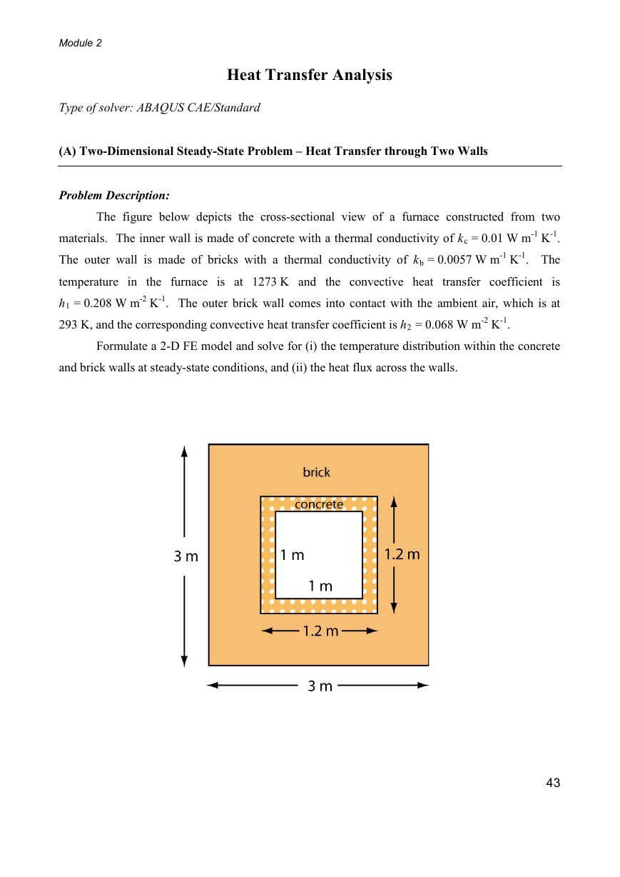
Formulate a 2-D FE model and solve for (i) the temperature distribution within the concrete
Type of solver: ABAQUS CAE/Standard
(A) Two-Dimensional Steady-State Problem – Heat Transfer through Two Walls
Problem Description:
The figure below depicts the cross-sectional view of a furnace constructed from two
materials. The inner wall is made of concrete with a thermal conductivity of kc = 0.01 W m-1 K-1.
The outer wall is made of bricks with a thermal conductivity of kb = 0.0057 W m-1 K-1. The
temperature in the furnace is at 1273 K and the convective heat transfer coefficient is
h1 = 0.208 W m-2 K-1. The outer brick wall comes into contact with the ambient air, which is at
293 K, and the corresponding convective heat transfer coefficient is h2 = 0.068 W m-2 K-1.
and brick walls at steady-state conditions, and (ii) the heat flux across the walls.
43
�
Module 2
SOLUTION:
• Start ABAQUS/CAE. At the Start Session dialog box, click Create Model Database.
• From the main menu bar, select ModelCreate. The Edit Model Attributes dialog box
appears, name the model 2D_Walls
A. MODULE PART
Under the Part module, we will construct the two parts (i.e. walls): (i) Brick and (ii) Concrete
1. From the main menu bar, select PartCreate
2. The Create Part dialog box appears. Name the part Brick and fill in the rest of the options as
in Fig.A1. Click Continue to create the part.
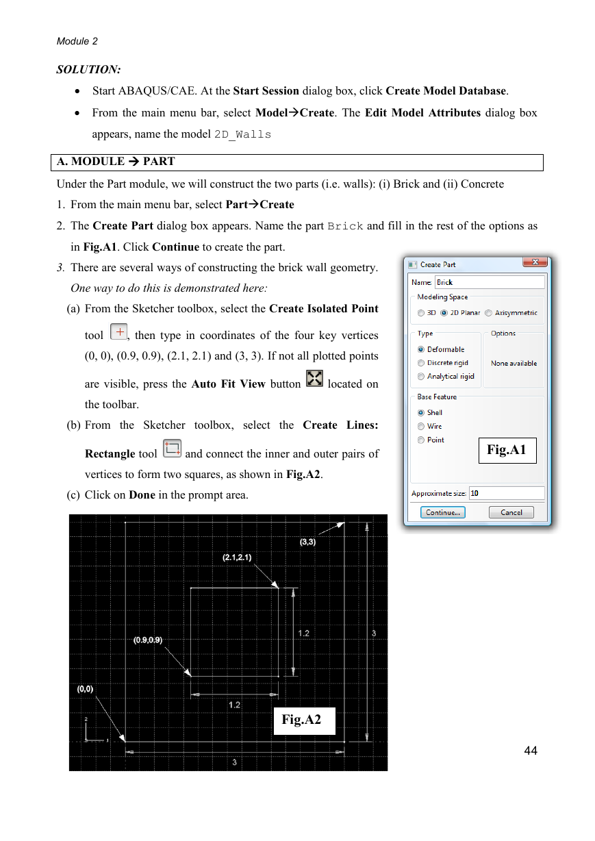
3. There are several ways of constructing the brick wall geometry.
One way to do this is demonstrated here:
(a) From the Sketcher toolbox, select the Create Isolated Point
tool
, then type in coordinates of the four key vertices
(0, 0), (0.9, 0.9), (2.1, 2.1) and (3, 3). If not all plotted points
are visible, press the Auto Fit View button
the toolbar.
located on
(b) From the Sketcher toolbox, select the Create Lines:
Rectangle tool
vertices to form two squares, as shown in Fig.A2.
and connect the inner and outer pairs of
(c) Click on Done in the prompt area.
Fig.A2
Fig.A1
44
�
Module 2
4. Now construct the second part by following procedures similar to the ones outlined above. Name
the new part Concrete. The four key vertices are (0, 0), (0.1, 0.1), (1.1, 1.1) and (1.2, 1.2).
B. MODULE PROPERTY
(a) To define the materials:-
1. From the main menu bar, select MaterialCreate
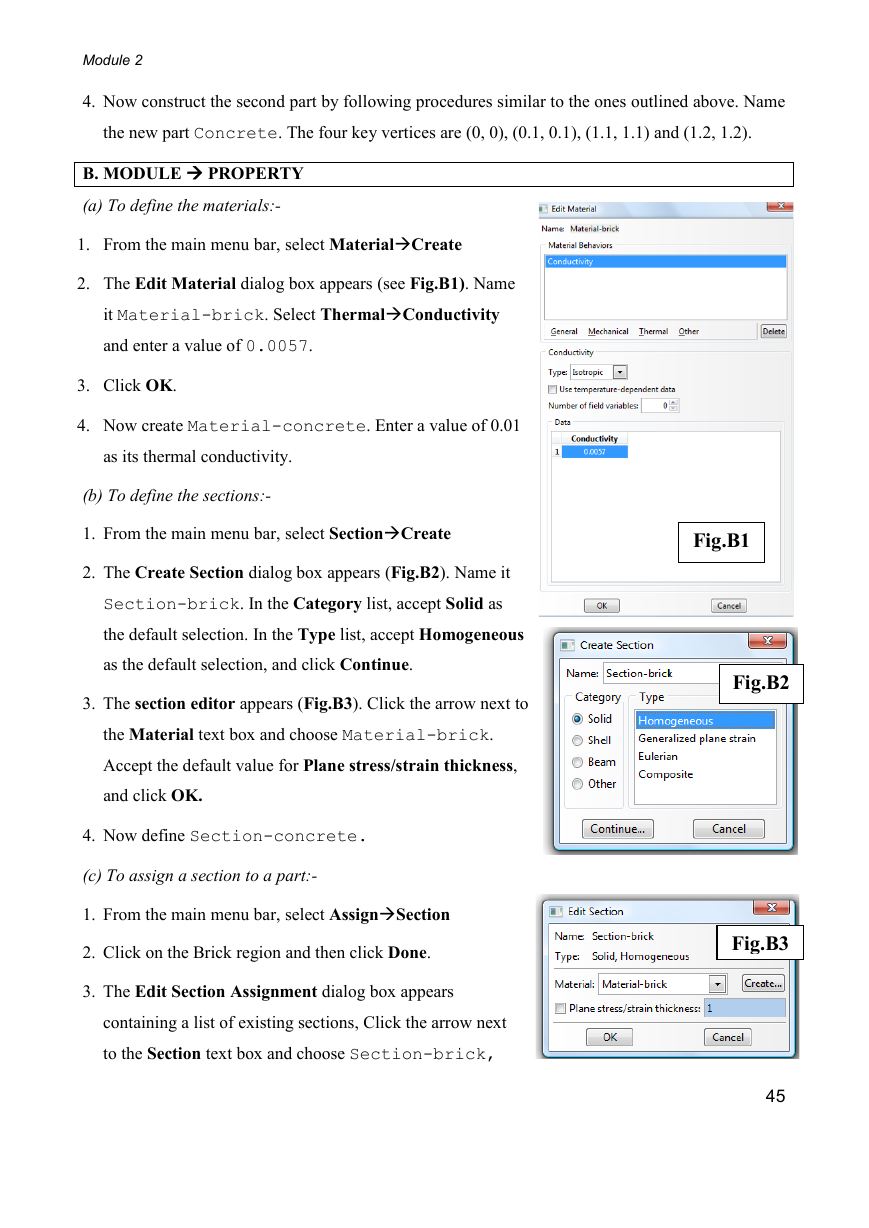
2. The Edit Material dialog box appears (see Fig.B1). Name
it Material-brick. Select ThermalConductivity
and enter a value of 0.0057.
3. Click OK.
4. Now create Material-concrete. Enter a value of 0.01
as its thermal conductivity.
(b) To define the sections:-
1. From the main menu bar, select SectionCreate
2. The Create Section dialog box appears (Fig.B2). Name it
Section-brick. In the Category list, accept Solid as
the default selection. In the Type list, accept Homogeneous
as the default selection, and click Continue.
3. The section editor appears (Fig.B3). Click the arrow next to
the Material text box and choose Material-brick.
Accept the default value for Plane stress/strain thickness,
and click OK.
4. Now define Section-concrete.
(c) To assign a section to a part:-
1. From the main menu bar, select AssignSection
2. Click on the Brick region and then click Done.
3. The Edit Section Assignment dialog box appears
containing a list of existing sections, Click the arrow next
to the Section text box and choose Section-brick,
Fig.B1
Fig.B2
Fig.B3
45
�
Module 2
and click OK.
Note: the colour of a part becomes aqua when it has been assigned a section.
5. Now assign Section-concrete to the concrete region.
C. MODULE ASSEMBLY
1. From the main menu bar, select InstanceCreate
2. The Create Instance dialog box appears (Fig.C1). Under
Parts, select Brick. For Instance Type, choose Independent
(mesh on instance). Toggle on Auto-offset from other
instances. Click OK.
3. Now create an instance for the part Concrete.
4. At this point, before we proceed onto assembling the instances,
Fig.C1
it would be useful to define several sets of surfaces for use in
later stages of the analysis. From the main menu bar, select
ToolsSurfaceCreate. The Create Surface dialog box
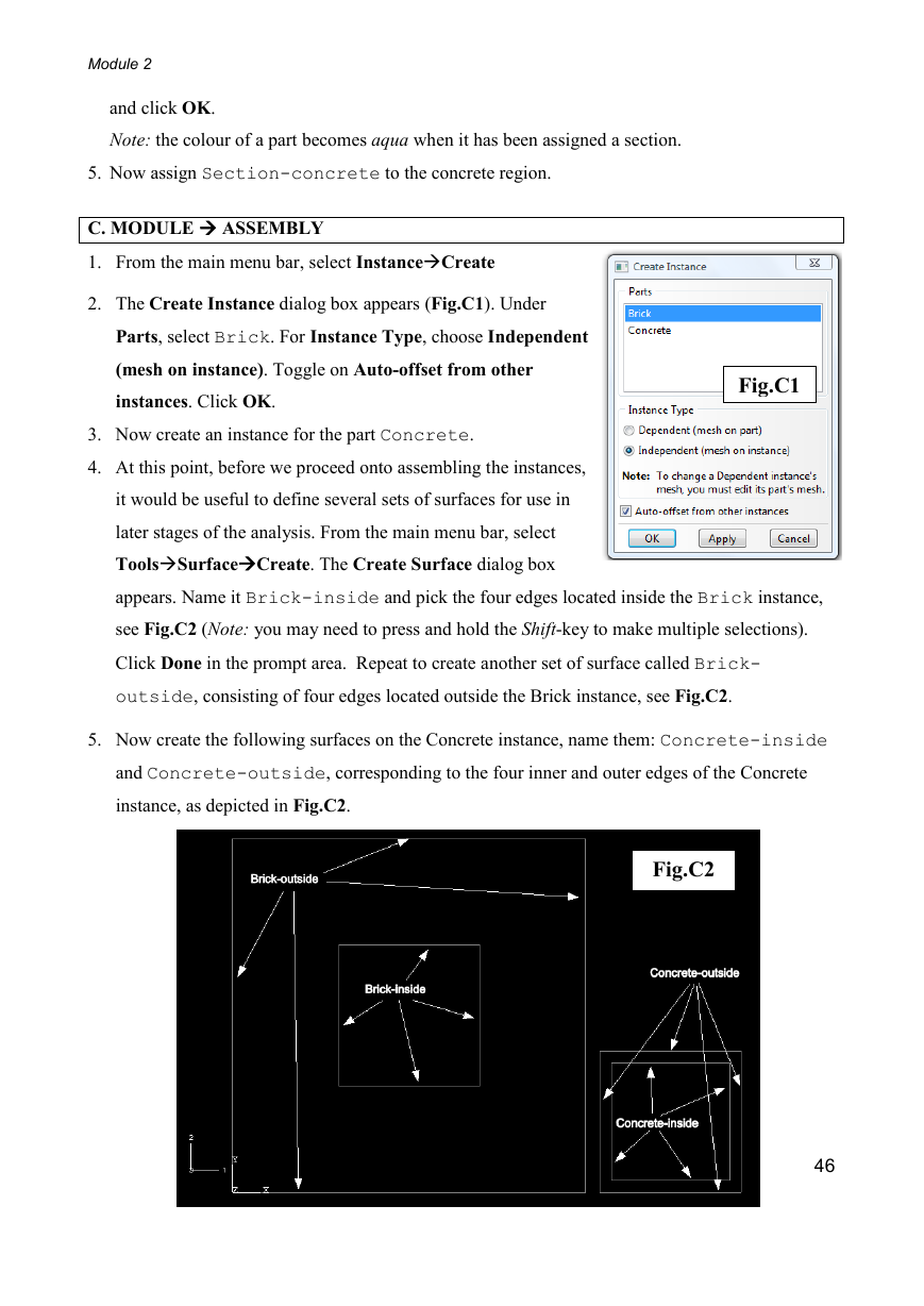
appears. Name it Brick-inside and pick the four edges located inside the Brick instance,
see Fig.C2 (Note: you may need to press and hold the Shift-key to make multiple selections).
Click Done in the prompt area. Repeat to create another set of surface called Brick-
outside, consisting of four edges located outside the Brick instance, see Fig.C2.
5. Now create the following surfaces on the Concrete instance, name them: Concrete-inside
and Concrete-outside, corresponding to the four inner and outer edges of the Concrete
instance, as depicted in Fig.C2.
Fig.C2
46
�
Module 2
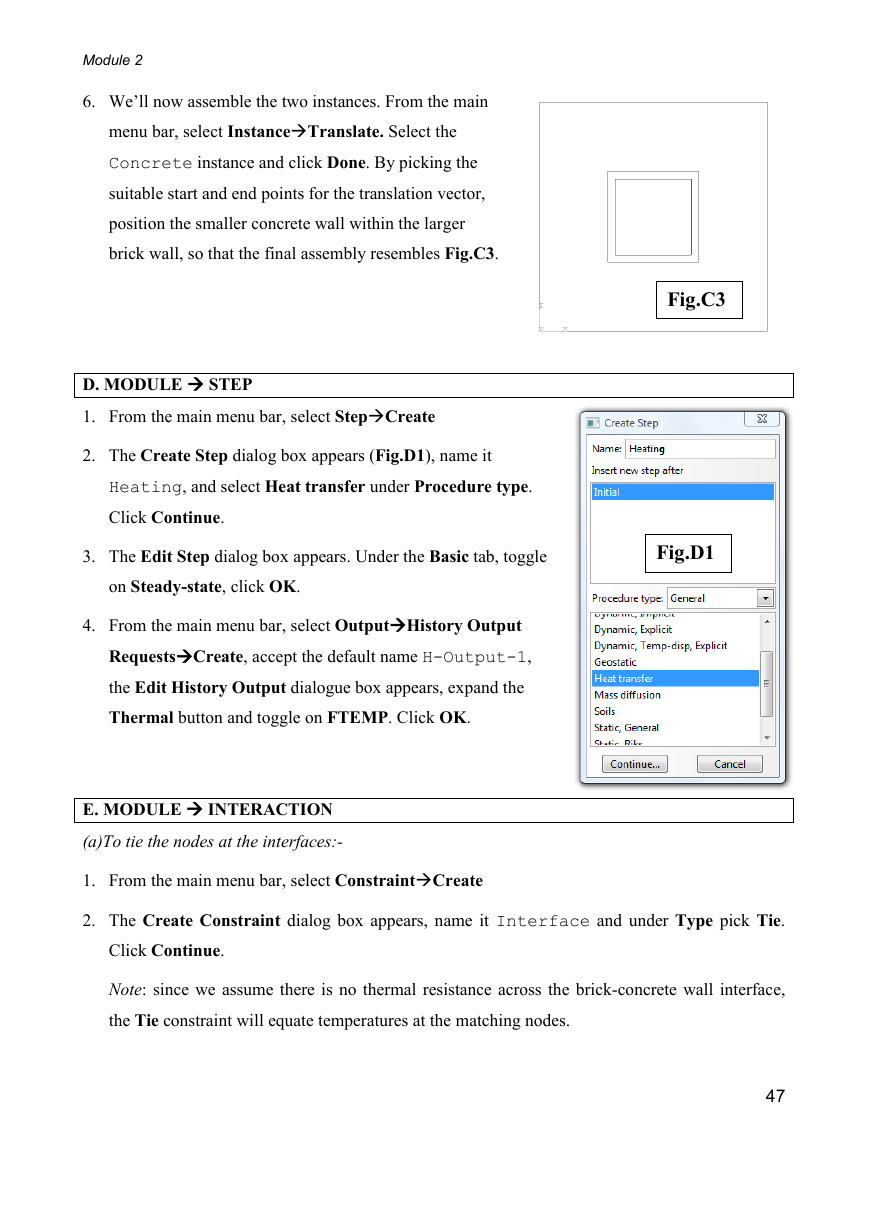
6. We’ll now assemble the two instances. From the main
menu bar, select InstanceTranslate. Select the
Concrete instance and click Done. By picking the
suitable start and end points for the translation vector,
position the smaller concrete wall within the larger
brick wall, so that the final assembly resembles Fig.C3.
D. MODULE STEP
1. From the main menu bar, select StepCreate
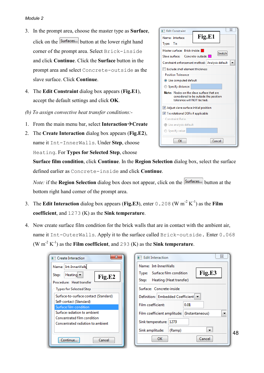
2. The Create Step dialog box appears (Fig.D1), name it
Heating, and select Heat transfer under Procedure type.
Click Continue.
Fig.C3
3. The Edit Step dialog box appears. Under the Basic tab, toggle
Fig.D1
on Steady-state, click OK.
4. From the main menu bar, select OutputHistory Output
RequestsCreate, accept the default name H-Output-1,
the Edit History Output dialogue box appears, expand the
Thermal button and toggle on FTEMP. Click OK.
E. MODULE INTERACTION
(a)To tie the nodes at the interfaces:-
1. From the main menu bar, select ConstraintCreate
2. The Create Constraint dialog box appears, name it Interface and under Type pick Tie.
Click Continue.
Note: since we assume there is no thermal resistance across the brick-concrete wall interface,
the Tie constraint will equate temperatures at the matching nodes.
47
�
Module 2
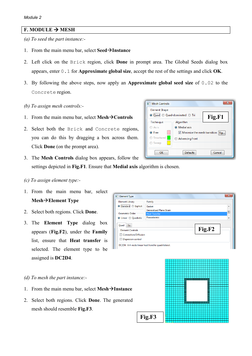
Fig.E1
3. In the prompt area, choose the master type as Surface,
button at the lower right hand
click on the
corner of the prompt area. Select Brick-inside
and click Continue. Click the Surface button in the
prompt area and select Concrete-outside as the
slave surface. Click Continue.
4. The Edit Constraint dialog box appears (Fig.E1),
accept the default settings and click OK.
(b) To assign convective heat transfer conditions:-
1. From the main menu bar, select InteractionCreate
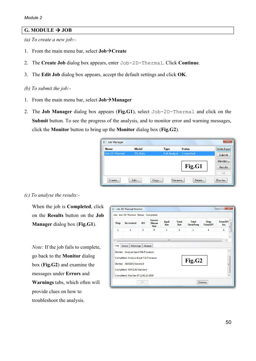
2. The Create Interaction dialog box appears (Fig.E2),
name it Int-InnerWalls. Under Step, choose
Heating. For Types for Selected Step, choose
Surface film condition, click Continue. In the Region Selection dialog box, select the surface
defined earlier as Concrete-inside and click Continue.
Note: if the Region Selection dialog box does not appear, click on the
bottom right hand corner of the prompt area.
button at the
3. The Edit Interaction dialog box appears (Fig.E3), enter 0.208 (W m-2 K-1) as the Film
coefficient, and 1273 (K) as the Sink temperature.
4. Now create surface film condition for the brick walls that are in contact with the ambient air,
name it Int-OuterWalls. Apply it to the surface called Brick-outside. Enter 0.068
(W m-2 K-1) as the Film coefficient, and 293 (K) as the Sink temperature.
Fig.E2
Fig.E3
48
�
Module 2
F. MODULE MESH
(a) To seed the part instance:-
1. From the main menu bar, select SeedInstance
2. Left click on the Brick region, click Done in prompt area. The Global Seeds dialog box
appears, enter 0.1 for Approximate global size, accept the rest of the settings and click OK.
3. By following the above steps, now apply an Approximate global seed size of 0.02 to the
Concrete region.
(b) To assign mesh controls:-
1. From the main menu bar, select MeshControls
2. Select both the Brick and Concrete regions,
you can do this by dragging a box across them.
Click Done (on the prompt area).
3. The Mesh Controls dialog box appears, follow the
settings depicted in Fig.F1. Ensure that Medial axis algorithm is chosen.
Fig.F1
Fig.F2
(c) To assign element type:-
1. From the main menu bar, select
MeshElement Type
2. Select both regions. Click Done.
3. The Element Type dialog box
appears (Fig.F2), under the Family
list, ensure that Heat transfer is
selected. The element type to be
assigned is DC2D4.
(d) To mesh the part instance:-
1. From the main menu bar, select MeshInstance
2. Select both regions. Click Done. The generated
mesh should resemble Fig.F3.
Fig.F3
49
�
Module 2
G. MODULE JOB
(a) To create a new job:-
1. From the main menu bar, select JobCreate
2. The Create Job dialog box appears, enter Job-2D-Thermal. Click Continue.
3. The Edit Job dialog box appears, accept the default settings and click OK.
(b) To submit the job:-
1. From the main menu bar, select JobManager
2. The Job Manager dialog box appears (Fig.G1), select Job-2D-Thermal and click on the
Submit button. To see the progress of the analysis, and to monitor error and warning messages,
click the Monitor button to bring up the Monitor dialog box (Fig.G2).
(c) To analyse the results:-
When the job is Completed, click
on the Results button on the Job
Manager dialog box (Fig.G1).
Note: If the job fails to complete,
go back to the Monitor dialog
box (Fig.G2) and examine the
messages under Errors and
Warnings tabs, which often will
provide clues on how to
troubleshoot the analysis.
Fig.G1
Fig.G2
50
�


 2023年江西萍乡中考道德与法治真题及答案.doc
 2012年重庆南川中考生物真题及答案.doc
 2013年江西师范大学地理学综合及文艺理论基础考研真题.doc
 2020年四川甘孜小升初语文真题及答案I卷.doc
 2020年注册岩土工程师专业基础考试真题及答案.doc
 2023-2024学年福建省厦门市九年级上学期数学月考试题及答案.doc
 2021-2022学年辽宁省沈阳市大东区九年级上学期语文期末试题及答案.doc
 2022-2023学年北京东城区初三第一学期物理期末试卷及答案.doc
 2018上半年江西教师资格初中地理学科知识与教学能力真题及答案.doc
 2012年河北国家公务员申论考试真题及答案-省级.doc
 2020-2021学年江苏省扬州市江都区邵樊片九年级上学期数学第一次质量检测试题及答案.doc
 2022下半年黑龙江教师资格证中学综合素质真题及答案.doc