1254
978-1-4577-1348-4/11/$26.00 ©2011 IEEE
2011 IEEE 22nd International Symposium on Personal, Indoor and Mobile Radio Communications
Usability of Apple iPhones for Inertial Navigation Systems
corina.schindhelm@siemens.com
florian.gschwandtner@ifi.lmu.de
CT T DE IT 1
Siemens AG
Department for Informatics
Corina Kim Schindhelm
Florian Gschwandtner
I. INTRODUCTION
University of Munich
Munich, Germany
Munich, Germany
For that reason, inertial systems are used for indoor posi-
tioning. Knowing an initial position, all subsequent positions
can be calculated using various sensor data, which do not
require any infrastructure and ensure the user’s privacy.
A lot of research was done in the area of inertial
positioning systems using expensive and distinct devices.
However, since modern devices are often equipped with
inertial sensors, they could be used for common inertial
positioning systems. Hence, we decided to examine two
common devices, the Apple iPhone 3GS and the iPhone
4, on their capability of being used for inertial positioning
using standard algorithms.
The remainder is structured as followed: Sec. II introduces
inertial navigation and list some reference work. Sec. III
describes the devices, the algorithms and filters applied. Sec.
IV introduces preliminarily results and Sec. V concludes the
paper with future work.
II. INERTIAL NAVIGATION SYSTEMS
Inertial Navigation is an autonomous navigation aid.
Based on an initial position, orientation (direction), and
velocity (speed), an INS continuously calculates consecutive
positions of a moving target. Thus, an INS consists of an
entity equipped with sensors, typically an inertial measure-
ment unit (IMU), which measures the data and an algorithm,
which processes the data and calculates positions.
The IMU is responsible for measuring acceleration and
rotation. To obtain initial orientation of a full six-degree of
freedom IMU, at least six sensors, three for the rotation
(pitch, roll, yaw) and three for the acceleration (x, y, z) in
every direction are needed.
The algorithm that processes the IMU data is called
dead reckoning. Based on an initial position, the current
position is calculated with the aid of the current direction
of motion, the velocity or the distance traveled. Besides
the initial position, this system is completely independent
from outside data sources, and thus allows for a privacy
friendly self positioning. However, drawbacks like drifts and
incorrect positions can result from small sensor measurement
deviations.
Woodman [3] describes the principle of inertial navigation
and creates a simulator where sensor data can be observed
Michael Banholzer
Department for Informatics
University of Munich
Munich, Germany
banholzer@cip.ifi.lmu.de
Abstract—In recent decades, many indoor positioning tech-
niques have been researched and some approaches have even
been developed into consumer products. Most of them have
been deployed into companies which benefit
from indoor
asset tracking. However, for public buildings like libraries or
transportation systems, no direct benefit exists by installing
expensive systems. Inertial navigation systems offer a form
of positioning which is almost completely independent from
external infrastructures, inexpensive and privacy friendly. As
prices for sensors continuously drop, mobile terminals, such
as cell phones or tablet PCs, are being equipped with various
additional components, like GPS, cameras and light sensors,
and moreover gyroscopes, compasses and accelerometers in-
tegration is also becoming commonplace. These last three
components enable inertial navigation systems to calculate the
position of the device. In this paper, we selected two devices,
the iPhone 3GS and the iPhone 4, to analyze their sensors for
usability of an inertial navigation system. For each device a
common strapdown algorithm was implemented and varying
standard filters applied to clean the output data stream of
the sensors. Finally, we present the results, which are diverse
according to the devices.
Keywords-Inertial Navigation System, INS, Apple iPhone
Indoor positioning techniques are not hypothetical re-
search theories anymore but have been deployed into compa-
nies with sufficient funds to invest in expensive high preci-
sion technologies like Ultra Wide Band . Conversely, public
buildings have no monetary incentive and must find low cost
solutions. Some institutions use existing hardware and add
software to achieve an additional advantage for visitors, like
in the New York Museum of Natural History [1], which
allows user to find their own position and corresponding
exhibit information on a map via WiFi positioning.
Independent of the underlying technology, K”upper [2]
outlines four different positioning topologies based on which
component measures signals and/or calculates the position:
Network based, terminal assisted, terminal based and net-
work assisted. All these solutions depend to a greater or
lesser extent on the infrastructure controlled by a third party
which can affect the user’s privacy. Therefore, it is important
to reduce the dependency on a foreign infrastructure and to
make it impossible for a third party to detect or localize the
user.
�
1255
(6)
By integrating |ag|, the velocity vg(t) and the displace-
ment sp(t) are obtained.
vg(t) = vg(0) +
|ag|(t)dt
a =α
x α
y α
ag = a A(φ θ ψ)
z
T
t
t−δt
t
sp(t) =
vg(t)dt
t−δt
(5)
(7)
(8)
The vector vg(0) represents the past velocity. To obtain
the current velocity at time t the previous velocity has to
be added to the integral of the vector ag. The vector for the
correct direction is calculated by normalizing and scaling vg
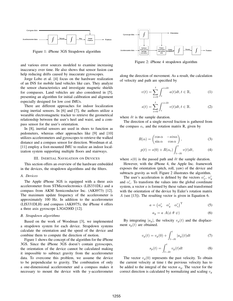
Figure 2: iPhone 4 strapdown algorithm
along the direction of movement. As a result, the calculation
of velocity and path are specified by
i+δt
i+δt
i
t
t
i=0
i=0
i
v(t) =
s(t) =
a(t)dt, t ∈ R,
v(t)dt, t ∈ R.
(1)
(2)
where δt is the sample duration.
The direction of a single moved fraction is gathered from
the compass αc and the rotation matrix R, given by
cos α −sinα
t
cos α
sin α
R(α) =
p(t) = s(0) + R(αc)
t−δt
,
(3)
(4)
v(t)dt,
The user’s acceleration is defined by the vectors α
where s(0) is the passed path and δt the sample duration.
However, with the iPhone 4, the Apple Inc. framework
exposes the orientation (pitch, roll, yaw) of the device and
subtracts gravity as well. Figure 2 illustrates the algorithm.
x, α
y
and α
z. To transform the values into the global coordinate
system, a vector a is formed by these values and transformed
with the orientation of the device by Euler’s rotation matrix
A (see [13]). The resulting vector is given in Equation 6.
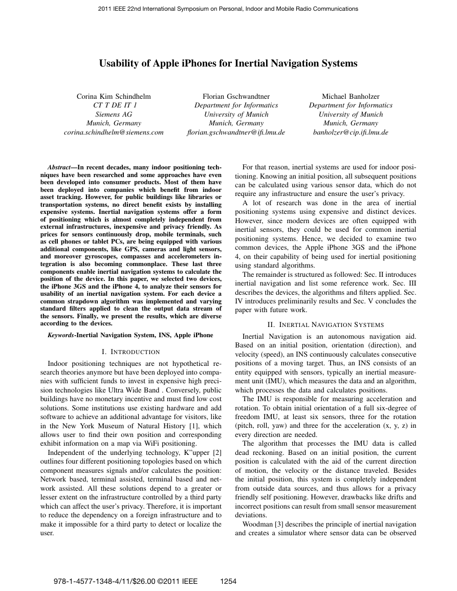
Figure 1: iPhone 3GS Strapdown algorithm
and various error sources modeled to examine increasing
inaccuracy over time. He also shows that sensor fusion can
help reducing drifts caused by inaccurate gyroscopes.
Jorge Lobo et al. [4] focus on the hardware realization
of an INS for mobile land vehicles like cars. They analyze
the sensor characteristics and investigate magnetic shields
for compasses. Land vehicles are also considered in [5],
presenting an algorithm for initial calibration and alignment
especially designed for low cost IMUs.
There are different approaches for indoor localization
using inertial sensors. In [6] and [7], the authors utilize a
wearable electromagnetic tracker to retrieve the geometrical
relationship between the user’s heel and waist, and a com-
pass sensor for the user’s orientation.
In [8], inertial sensors are used in shoes to function as
pedometers, whereas other approaches like [9] and [10]
utilizes accelerometers and gyroscopes to retrieve the walked
distance and a compass sensor for direction. Woodman et al.
[11] employ a foot-mounted IMU to realize an indoor local-
ization system supporting multiple floors and stairways.
III. INERTIAL NAVIGATION ON DEVICES
This section offers an overview of the hardware embedded
in the devices, the strapdown algorithms and the filters.
A. Devices
The Apple iPhone 3GS is equipped with a three axis
accelerometer from STMicroelectronics (LIS331DL) and a
compass from AKM Semiconductor Inc. (AK8973) [12].
The maximum update frequency of the accelerometer is
approximately 100 Hz. In addition to the accelerometer
(LIS331DLH) and compass (AK8975), the iPhone 4 offers
a three axis gyroscope L3G4200D [12].
B. Strapdown algorithms
Based on the work of Woodman [3], we implemented
a strapdown system for each device. Strapdown systems
calculate the orientation and the speed of the device and
combine them to compute the direction of motion.
Figure 1 shows the concept of the algorithm for the iPhone
3GS. Since the iPhone 3GS doesn’t contain gyroscopes,
the orientation of the device cannot be calculated making
it
impossible to subtract gravity from the accelerometer
data. To overcome this problem, we assume the device
to be perpendicular to gravity. The combination of only
a one-dimensional accelerometer and a compass makes it
necessary to mount
the device with the y-accelerometer
∫∫Compass dataAccelerometer dataVelocityPositionInitialPositionWayProjectaccelerationonto globalaxes∫∫VelocityGlobalAcceleration∫Subtractearth gravitythroughorientationGyroscope dataOrientationAccelerometer dataPosition�
1256
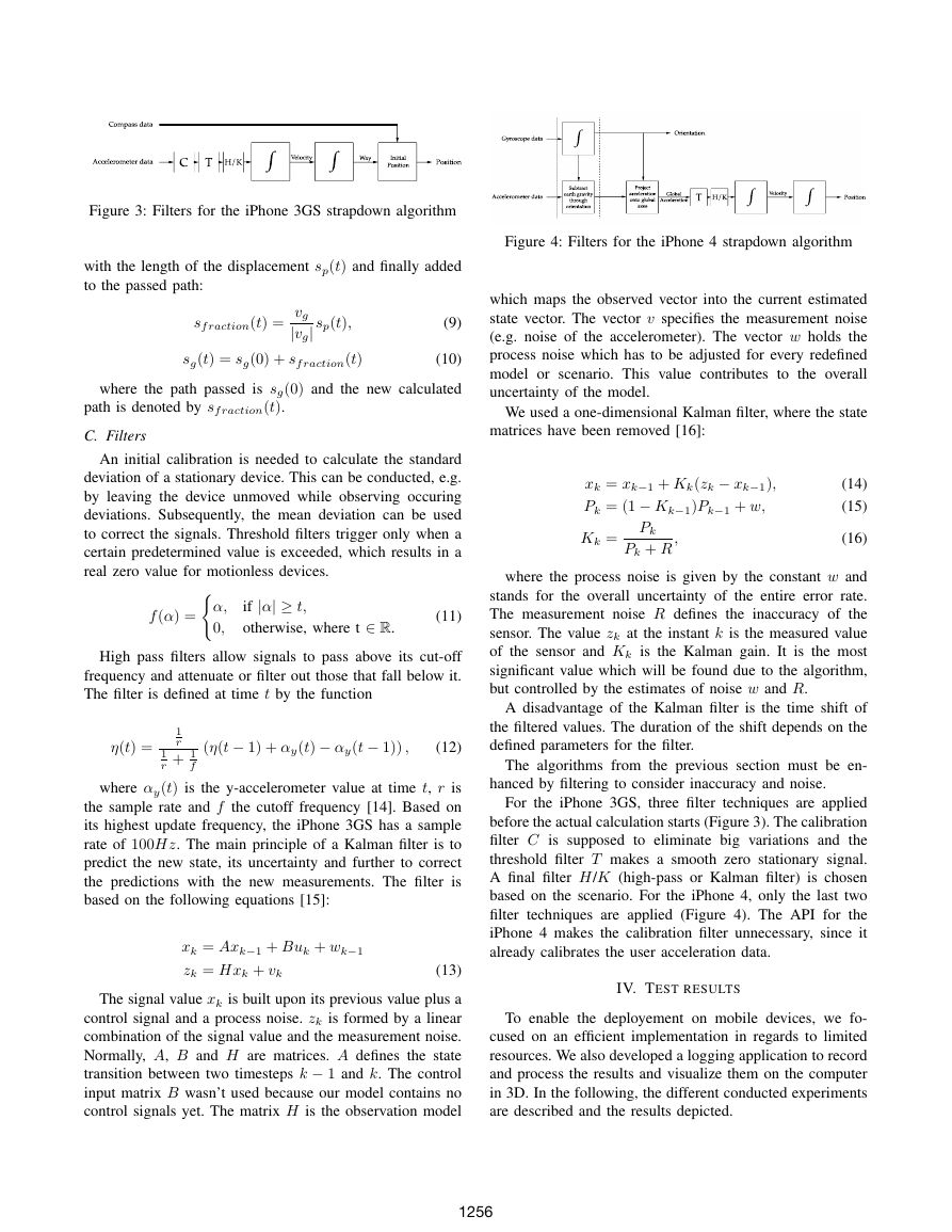
Figure 3: Filters for the iPhone 3GS strapdown algorithm
with the length of the displacement sp(t) and finally added
to the passed path:
sf raction(t) =
vg|vg| sp(t),
sg(t) = sg(0) + sf raction(t)
(9)
(10)
where the path passed is sg(0) and the new calculated
path is denoted by sf raction(t).
C. Filters
An initial calibration is needed to calculate the standard
deviation of a stationary device. This can be conducted, e.g.
by leaving the device unmoved while observing occuring
deviations. Subsequently, the mean deviation can be used
to correct the signals. Threshold filters trigger only when a
certain predetermined value is exceeded, which results in a
real zero value for motionless devices.
f (α) =
if |α| ≥ t,
otherwise, where t ∈ R.
α,
0,
(11)
High pass filters allow signals to pass above its cut-off
frequency and attenuate or filter out those that fall below it.
The filter is defined at time t by the function
η(t) =
1
r
1
r + 1
f
(η(t − 1) + αy(t) − αy(t − 1)) ,
(12)
where αy(t) is the y-accelerometer value at time t, r is
the sample rate and f the cutoff frequency [14]. Based on
its highest update frequency, the iPhone 3GS has a sample
rate of 100Hz. The main principle of a Kalman filter is to
predict the new state, its uncertainty and further to correct
the predictions with the new measurements. The filter is
based on the following equations [15]:
xk = Axk−1 + Buk + wk−1
zk = Hxk + vk
(13)
The signal value xk is built upon its previous value plus a
control signal and a process noise. zk is formed by a linear
combination of the signal value and the measurement noise.
Normally, A, B and H are matrices. A defines the state
transition between two timesteps k − 1 and k. The control
input matrix B wasn’t used because our model contains no
control signals yet. The matrix H is the observation model
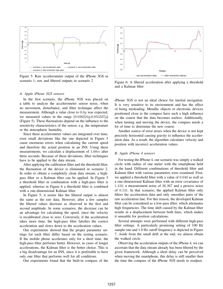
Figure 4: Filters for the iPhone 4 strapdown algorithm
which maps the observed vector into the current estimated
state vector. The vector v specifies the measurement noise
(e.g. noise of the accelerometer). The vector w holds the
process noise which has to be adjusted for every redefined
model or scenario. This value contributes to the overall
uncertainty of the model.
We used a one-dimensional Kalman filter, where the state
matrices have been removed [16]:
xk = xk−1 + Kk(zk − xk−1),
Pk = (1 − Kk−1)Pk−1 + w,
Kk =
Pk
Pk + R
,
(14)
(15)
(16)
where the process noise is given by the constant w and
stands for the overall uncertainty of the entire error rate.
The measurement noise R defines the inaccuracy of the
sensor. The value zk at the instant k is the measured value
of the sensor and Kk is the Kalman gain. It is the most
significant value which will be found due to the algorithm,
but controlled by the estimates of noise w and R.
A disadvantage of the Kalman filter is the time shift of
the filtered values. The duration of the shift depends on the
defined parameters for the filter.
The algorithms from the previous section must be en-
hanced by filtering to consider inaccuracy and noise.
For the iPhone 3GS, three filter techniques are applied
before the actual calculation starts (Figure 3). The calibration
filter C is supposed to eliminate big variations and the
threshold filter T makes a smooth zero stationary signal.
A final filter H/K (high-pass or Kalman filter) is chosen
based on the scenario. For the iPhone 4, only the last two
filter techniques are applied (Figure 4). The API for the
iPhone 4 makes the calibration filter unnecessary, since it
already calibrates the user acceleration data.
IV. TEST RESULTS
To enable the deployement on mobile devices, we fo-
cused on an efficient implementation in regards to limited
resources. We also developed a logging application to record
and process the results and visualize them on the computer
in 3D. In the following, the different conducted experiments
are described and the results depicted.
∫∫Compass dataAccelerometer dataVelocityPositionInitialPositionWayCTH/KProjectaccelerationonto globalaxes∫∫VelocityGlobalAcceleration∫Subtractearth gravitythroughorientationGyroscope dataOrientationAccelerometer dataPositionTH/K�
1257
iPhone 3GS is not an ideal choice for inertial navigation.
It is very sensitive to its environment and has the effect
of being misleading. Metallic objects or electronic devices
positioned close to the compass have such a high influence
on the course that the data becomes useless. Additionally,
when turning and moving the device, the compass needs a
lot of time to determine the new course.
Another source of error arises when the device is not kept
precisely horizontal causing gravity to influence the acceler-
ation data. As a result, the algorithm calculates velocity and
position with incorrect acceleration values.
B. Apple iPhone 4 sensors
For testing the IPhone 4, our scenario was simply a walked
circle with radius of one meter with the smartphone held
in the hand. Different combinations of threshold filter and
Kalman filter with various parameters were examined. First,
we applied a threshold filter with a value of 0.040 as well as
a one-dimensional Kalman filter with an error covariance of
1.410, a measurement noise of 26.367 and a process noise
of 0.131. In that scenario, the applied Kalman filter only
filters the acceleration data and only smoothes parts of the
raw acceleration line. For this reason, the developed Kalman
filter can be considered as a low-pass filter, which attenuates
high frequencies. The time shift caused by the Kalman filter
results in a displacement between both lines, which makes
it unusable for position calculations.
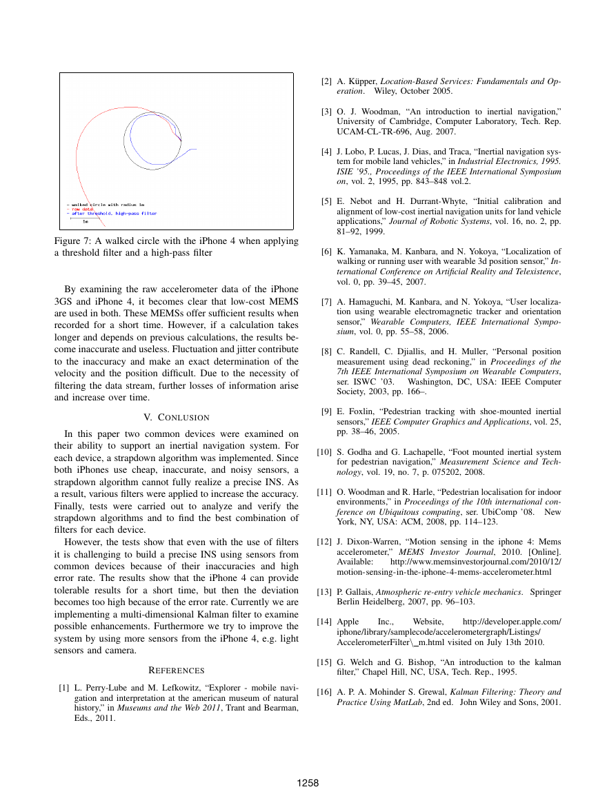
Several attempts were performed with different high-pass
filter settings. A particularly promising setting of 100 Hz
sample rate and 1.0 Hz cutoff frequency is depicted in Figure
7. Aside from the small drift at the end, we almost obtain
the walked circle.
Observing the acceleration outputs of the iPhone 4, we can
ascertain that the data stream already has been filtered by the
given framework. Although a short delay can be perceived
when moving the smartphone, this delay is still smaller then
the time the compass of the iPhone 3GS needs to readjust.
Figure 6: A filtered acceleration after applying a threshold
and a Kalman filter
Figure 5: Raw accelerometer output of the iPhone 3GS in
scenario 1; raw and filtered outputs in scenario 2
A. Apple iPhone 3GS sensors
In the first scenario,
the iPhone 3GS was placed on
a table to analyze the accelerometer sensor noise, when
no movement, disturbance, and filter technique affect the
measurement. Although a value close to 0.0g was expected,
we measured values in the range [0.036224g;0.054337g]
(Figure 5). These fluctuations depend on the influence to the
sensitivity characteristics of the sensor, e.g. the temperature
or the atmospheric humidity.
Since these accelerometer values are integrated over time,
even small deviations like the one depicted in Figure 5
cause enormous errors when calculating the current speed
and therefore the actual position in an INS. Using these
measurements, we calculate a displacement of 1.68m after
three seconds. Because of these deviations, filter techniques
have to be applied to the data stream.
After applying the calibration filter and the threshold filter,
the fluctuation of the device is eliminated in scenario 2.
In order to obtain a completely clean data stream, a high-
pass filter or a Kalman filter can be applied. In Figure 5
a threshold filter in combination with a high-pass filter is
applied, whereas in Figure 6 a threshold filter is combined
with a one-dimensional Kalman filter.
In Figure 5, it seems like the filtered output is almost
the same as the raw data. However, after a few samples
the filtered values decrease as observed in the first and
second amplitude. In some scenarios, the decrease can be
an advantage for calculating the speed, since the velocity
is recalibrated close to zero. Conversely, if the acceleration
takes more time, the high-pass filter falsifies the correct
acceleration and slows down to the acceleration values.
Our experiments showed that the proper parameter set-
tings for each filter differ based on the testing scenario.
If the mobile phone accelerates only for a short time, the
high-pass filter performs better. However, in cases of longer
accelerations, the Kalman filter is the better choice. This is
a big disadvantage for an INS, since it is preferable to have
only one filter that performs well for all conditions.
Our experiments found that the built-in compass of the
-1-0,8-0,6-0,4-0,200,20,40,60,80,00,51,01,5Gforce[g]Time[s]scenario1:rawaccelerationdatascenario2:rawaccelerationdatascenario2:afterthreshold,high-pass-0,8-0,6-0,4-0,200,20,40,60,80,00,51,01,5Gforce[g]Time[s]rawaccelerationdataafterthreshold,kalman�
1258
By examining the raw accelerometer data of the iPhone
3GS and iPhone 4, it becomes clear that low-cost MEMS
are used in both. These MEMSs offer sufficient results when
recorded for a short time. However, if a calculation takes
longer and depends on previous calculations, the results be-
come inaccurate and useless. Fluctuation and jitter contribute
to the inaccuracy and make an exact determination of the
velocity and the position difficult. Due to the necessity of
filtering the data stream, further losses of information arise
and increase over time.
V. CONLUSION
In this paper two common devices were examined on
their ability to support an inertial navigation system. For
each device, a strapdown algorithm was implemented. Since
both iPhones use cheap, inaccurate, and noisy sensors, a
strapdown algorithm cannot fully realize a precise INS. As
a result, various filters were applied to increase the accuracy.
Finally, tests were carried out to analyze and verify the
strapdown algorithms and to find the best combination of
filters for each device.
However, the tests show that even with the use of filters
it is challenging to build a precise INS using sensors from
common devices because of their inaccuracies and high
error rate. The results show that the iPhone 4 can provide
tolerable results for a short time, but then the deviation
becomes too high because of the error rate. Currently we are
implementing a multi-dimensional Kalman filter to examine
possible enhancements. Furthermore we try to improve the
system by using more sensors from the iPhone 4, e.g. light
sensors and camera.
REFERENCES
[1] L. Perry-Lube and M. Lefkowitz, “Explorer - mobile navi-
gation and interpretation at the american museum of natural
history,” in Museums and the Web 2011, Trant and Bearman,
Eds., 2011.
Figure 7: A walked circle with the iPhone 4 when applying
a threshold filter and a high-pass filter
[2] A. K¨upper, Location-Based Services: Fundamentals and Op-
eration. Wiley, October 2005.
[3] O. J. Woodman, “An introduction to inertial navigation,”
University of Cambridge, Computer Laboratory, Tech. Rep.
UCAM-CL-TR-696, Aug. 2007.
[4] J. Lobo, P. Lucas, J. Dias, and Traca, “Inertial navigation sys-
tem for mobile land vehicles,” in Industrial Electronics, 1995.
ISIE ’95., Proceedings of the IEEE International Symposium
on, vol. 2, 1995, pp. 843–848 vol.2.
[5] E. Nebot and H. Durrant-Whyte, “Initial calibration and
alignment of low-cost inertial navigation units for land vehicle
applications,” Journal of Robotic Systems, vol. 16, no. 2, pp.
81–92, 1999.
[6] K. Yamanaka, M. Kanbara, and N. Yokoya, “Localization of
walking or running user with wearable 3d position sensor,” In-
ternational Conference on Artificial Reality and Telexistence,
vol. 0, pp. 39–45, 2007.
[7] A. Hamaguchi, M. Kanbara, and N. Yokoya, “User localiza-
tion using wearable electromagnetic tracker and orientation
sensor,” Wearable Computers, IEEE International Sympo-
sium, vol. 0, pp. 55–58, 2006.
[8] C. Randell, C. Djiallis, and H. Muller, “Personal position
measurement using dead reckoning,” in Proceedings of the
7th IEEE International Symposium on Wearable Computers,
ser. ISWC ’03. Washington, DC, USA: IEEE Computer
Society, 2003, pp. 166–.
[9] E. Foxlin, “Pedestrian tracking with shoe-mounted inertial
sensors,” IEEE Computer Graphics and Applications, vol. 25,
pp. 38–46, 2005.
[10] S. Godha and G. Lachapelle, “Foot mounted inertial system
for pedestrian navigation,” Measurement Science and Tech-
nology, vol. 19, no. 7, p. 075202, 2008.
[11] O. Woodman and R. Harle, “Pedestrian localisation for indoor
environments,” in Proceedings of the 10th international con-
ference on Ubiquitous computing, ser. UbiComp ’08. New
York, NY, USA: ACM, 2008, pp. 114–123.
[12] J. Dixon-Warren, “Motion sensing in the iphone 4: Mems
[Online].
http://www.memsinvestorjournal.com/2010/12/
accelerometer,” MEMS Investor Journal, 2010.
Available:
motion-sensing-in-the-iphone-4-mems-accelerometer.html
[13] P. Gallais, Atmospheric re-entry vehicle mechanics. Springer
Berlin Heidelberg, 2007, pp. 96–103.
[14] Apple
Inc.,
Website,
http://developer.apple.com/
iphone/library/samplecode/accelerometergraph/Listings/
AccelerometerFilter\ m.html visited on July 13th 2010.
[15] G. Welch and G. Bishop, “An introduction to the kalman
filter,” Chapel Hill, NC, USA, Tech. Rep., 1995.
[16] A. P. A. Mohinder S. Grewal, Kalman Filtering: Theory and
Practice Using MatLab, 2nd ed. John Wiley and Sons, 2001.
�


 2023年江西萍乡中考道德与法治真题及答案.doc
 2012年重庆南川中考生物真题及答案.doc
 2013年江西师范大学地理学综合及文艺理论基础考研真题.doc
 2020年四川甘孜小升初语文真题及答案I卷.doc
 2020年注册岩土工程师专业基础考试真题及答案.doc
 2023-2024学年福建省厦门市九年级上学期数学月考试题及答案.doc
 2021-2022学年辽宁省沈阳市大东区九年级上学期语文期末试题及答案.doc
 2022-2023学年北京东城区初三第一学期物理期末试卷及答案.doc
 2018上半年江西教师资格初中地理学科知识与教学能力真题及答案.doc
 2012年河北国家公务员申论考试真题及答案-省级.doc
 2020-2021学年江苏省扬州市江都区邵樊片九年级上学期数学第一次质量检测试题及答案.doc
 2022下半年黑龙江教师资格证中学综合素质真题及答案.doc