REB-3310 Operational Manual
REB-3310 Operational Manual
Version 1.0
2005/4/7
This document contains information highly confidential to RoyalTek Company
LTD (RoyalTek). It is provided for the sole purpose of the business discussions
between supplier and RoyalTek and is covered under the terms of the
applicable Non-Disclosure Agreements. Disclosure of this information to other
parties is prohibited without the written consent of RoyalTek.
Prepared by RoyalTek Company LTD.
8F,256 Yang Guang Street, Neihu Chiu,Taipei, Taiwan, R.O.C.
TEL: 886-2-77215000
FAX: 886-2-77215666
http://www.royaltek.com/contact
1
�
REB-3310 Operational Manual
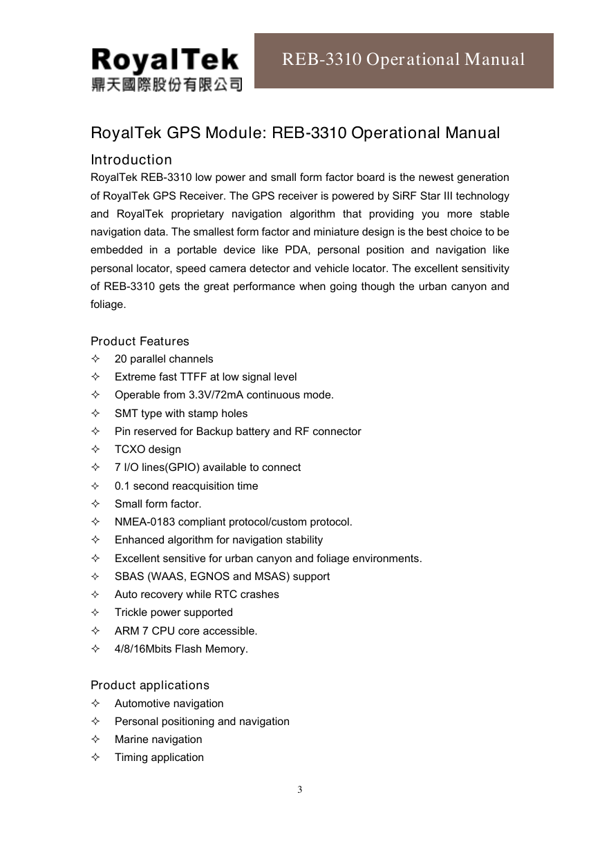
RoyalTek GPS Module: REB-3310 Operational Manual
INTRODUCTION.................................................................................................................... 3
PRODUCT FEATURES ....................................................................................................…. 3
PRODUCT APPLICATIONS .................................................................................................. 3
PRODUCT PICTURE................................................................................................................ 4
REB-3310 SERIES SYSTEM BLOCK DIAGRAM.................................................................. 6
REB-3310 TECHNIQUE SPECIFICATION..........................................................................…. 7
APPLICATION CIRCUIT .....................................................................................…………..
8
RECOMMENDED LAYOUT PAD ............................................................................………….. 9
GPS ANTENNA SPECIFICATION ................................................ ........................................ 10
MECHANICAL LAYOUT .......................................................................................……….…...11
HARDWARE INTERFACE …….............................................. ................................................12
DEFINITION OF PIN ASSIGNMENT ........................................................ ......................……13
SOFTWARE INTERFACE................................................................................…… ……….…15
NMEA V3.0 PROTOCOL..................................................................................…… ……….…15
GPS RECEIVER USER’S TIPS......................................................................................……..20
MTBF ESTIMATION………………….............................................. .......................……......… 21
PACKAGE SPECIFICATION AND ORDER INFORMATION................. ................……......…21
CONTACT INFORMATION SECTION....................................................................……......…21
2
�
REB-3310 Operational Manual
RoyalTek GPS Module: REB-3310 Operational Manual
Introduction
RoyalTek REB-3310 low power and small form factor board is the newest generation
of RoyalTek GPS Receiver. The GPS receiver is powered by SiRF Star III technology
and RoyalTek proprietary navigation algorithm that providing you more stable
navigation data. The smallest form factor and miniature design is the best choice to be
embedded in a portable device like PDA, personal position and navigation like
personal locator, speed camera detector and vehicle locator. The excellent sensitivity
of REB-3310 gets the great performance when going though the urban canyon and
foliage.
Product Features
20 parallel channels
Extreme fast TTFF at low signal level
Operable from 3.3V/72mA continuous mode.
SMT type with stamp holes
Pin reserved for Backup battery and RF connector
TCXO design
7 I/O lines(GPIO) available to connect
0.1 second reacquisition time
Small form factor.
NMEA-0183 compliant protocol/custom protocol.
Enhanced algorithm for navigation stability
Excellent sensitive for urban canyon and foliage environments.
SBAS (WAAS, EGNOS and MSAS) support
Auto recovery while RTC crashes
Trickle power supported
ARM 7 CPU core accessible.
4/8/16Mbits Flash Memory.
Product applications
Automotive navigation
Personal positioning and navigation
Marine navigation
Timing application
3
�
REB-3310 Operational Manual
Product Picture
REB-3310
Pin16
Pin 15
Pin 32
Pin 1
REB-3310 Interface Board
The interface board
PIN
1
2
3
4
5
6
7
8
9
10
11
12
13
REB-3300
VCC
GND
Boot select
RXA
TXA
TXB
RXB
GPIO_3
RF_ON
GND
GND_A
GND_A
GND_A
4
REB-3310
VCC_IN
GND
BOOT
RXA
TXA
TXB
RXB
GPIO_14
RF_ON
GND
GND_A
GND_A
GND_A
�
REB-3310 Operational Manual
GND_A
GND_A
GND_A
RF_IN
GND_A
V_ANT_IN
VCC_RF
V_BAT
Reset
GPIO_10
GPIO_6
GPIO_5
GPIO_7
GPIO_13
GPIO_15
PPS
GND
14
15
16
17
18
19
20
21
22
23
24
25
26
27
28
29
30
GND_A
GND_A
GND_A
RF_IN
GND_A
V_ANT
VCC_RF
Battery
IC_RESET
GPIO_10
GPIO_1
GPIO_5
GPIO_0
GPIO_13
GPIO_15
TIMEMARK
GND
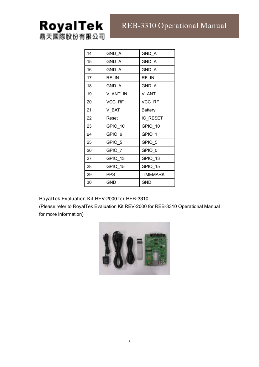
RoyalTek Evaluation Kit REV-2000 for REB-3310
(Please refer to RoyalTek Evaluation Kit REV-2000 for REB-3310 Operational Manual
for more information)
5
�
REB-3310 Operational Manual
REB-3310 Series System Block Diagram
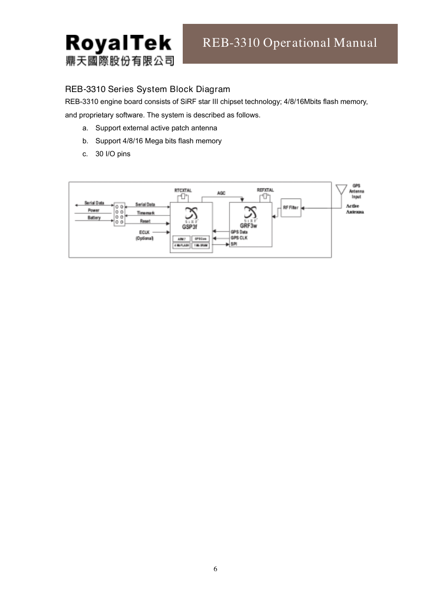
REB-3310 engine board consists of SiRF star III chipset technology; 4/8/16Mbits flash memory,
and proprietary software. The system is described as follows.
a. Support external active patch antenna
b. Support 4/8/16 Mega bits flash memory
c. 30 I/O pins
6
�
REB-3310 Operational Manual
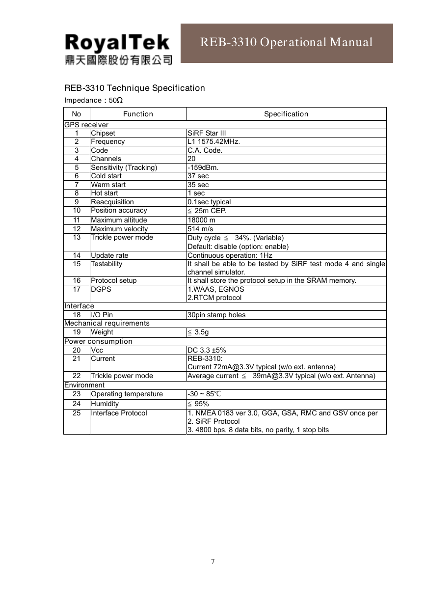
REB-3310 Technique Specification
ImpedanceG50[
No
Function
Specification
GPS receiver
Frequency
Sensitivity (Tracking)
1 Chipset
2
3 Code
4 Channels
5
6 Cold start
7 Warm start
8 Hot start
9 Reacquisition
10 Position accuracy
11 Maximum altitude
12 Maximum velocity
13 Trickle power mode
14 Update rate
15 Testability
16 Protocol setup
17 DGPS
Interface
18
I/O Pin
Mechanical requirements
19 Weight
Power consumption
20 Vcc
21 Current
22 Trickle power mode
Environment
23 Operating temperature
24 Humidity
25
Interface Protocol
SiRF Star III
L1 1575.42MHz.
C.A. Code.
20
-159dBm.
37 sec
35 sec
1 sec
0.1sec typical
25m CEP.
34%. (Variable)
18000 m
514 m/s
Duty cycle
Default: disable (option: enable)
Continuous operation: 1Hz
It shall be able to be tested by SiRF test mode 4 and single
channel simulator.
It shall store the protocol setup in the SRAM memory.
1.WAAS, EGNOS
2.RTCM protocol
30pin stamp holes
3.5g
DC 3.3 ±5%
REB-3310:
Current 72mA@3.3V typical (w/o ext. antenna)
Average current
39mA@3.3V typical (w/o ext. Antenna)
-30 ~ 85J
95%
1. NMEA 0183 ver 3.0, GGA, GSA, RMC and GSV once per
2. SiRF Protocol
3. 4800 bps, 8 data bits, no parity, 1 stop bits
7
�
REB-3310 Operational Manual
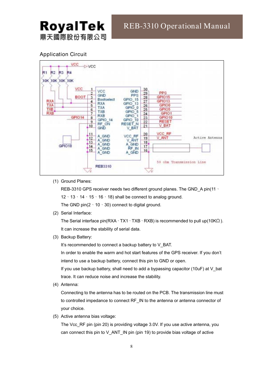
Application Circuit
(1) Ground Planes:
REB-3310 GPS receiver needs two different ground planes. The GND_A pin(11B
12B13B14B15B16B18) shall be connect to analog ground.
The GND pin(2B10B30) connect to digital ground.
(2) Serial Interface:
The Serial interface pin(RXABTX1BTXBBRXB) is recommended to pull up(10K[).
It can increase the stability of serial data.
(3) Backup Battery:
It’s recommended to connect a backup battery to V_BAT.
In order to enable the warm and hot start features of the GPS receiver. If you don’t
intend to use a backup battery, connect this pin to GND or open.
If you use backup battery, shall need to add a bypassing capacitor (10uF) at V_bat
trace. It can reduce noise and increase the stability.
(4) Antenna:
Connecting to the antenna has to be routed on the PCB. The transmission line must
to controlled impedance to connect RF_IN to the antenna or antenna connector of
your choice.
(5) Active antenna bias voltage:
The Vcc_RF pin (pin 20) is providing voltage 3.0V. If you use active antenna, you
can connect this pin to V_ANT_IN pin (pin 19) to provide bias voltage of active
8
�



 2023年江西萍乡中考道德与法治真题及答案.doc
 2012年重庆南川中考生物真题及答案.doc
 2013年江西师范大学地理学综合及文艺理论基础考研真题.doc
 2020年四川甘孜小升初语文真题及答案I卷.doc
 2020年注册岩土工程师专业基础考试真题及答案.doc
 2023-2024学年福建省厦门市九年级上学期数学月考试题及答案.doc
 2021-2022学年辽宁省沈阳市大东区九年级上学期语文期末试题及答案.doc
 2022-2023学年北京东城区初三第一学期物理期末试卷及答案.doc
 2018上半年江西教师资格初中地理学科知识与教学能力真题及答案.doc
 2012年河北国家公务员申论考试真题及答案-省级.doc
 2020-2021学年江苏省扬州市江都区邵樊片九年级上学期数学第一次质量检测试题及答案.doc
 2022下半年黑龙江教师资格证中学综合素质真题及答案.doc