REV-2000 Operational Manual
RoyalTek Evaluation Kit
REV-2000 Operational Manual
Version 1.1
2001/7/4
This document contains information highly confidential to RoyalTek Company LTD (RoyalTek). It
is provided for the sole purpose of the business discussions between supplier and RoyalTek and
is covered under the terms of the applicable Non-Disclosure Agreements. Disclosure of this
information to other parties is prohibited without the written consent of RoyalTek.
Prepared by
RoyalTek Company LTD.
1071, Chung Cheng Rd., Suite 9F-1
Tao Yuan City, Taiwan, R.O.C.
TEL: 886-3-3569666
FAX: 886-3-3580050
E-Mail: sales@royaltek.com
http://www.royaltek.com
�
RoyalTek GPS Receiver REB-2000/REB-12R REV-2000 Operational Manual
RoyalTek Evaluation Kit REV-2000 Operational Manual
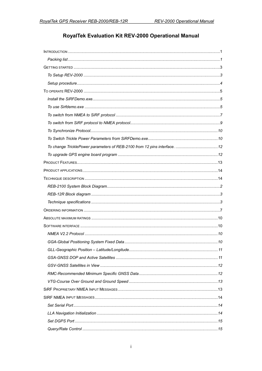
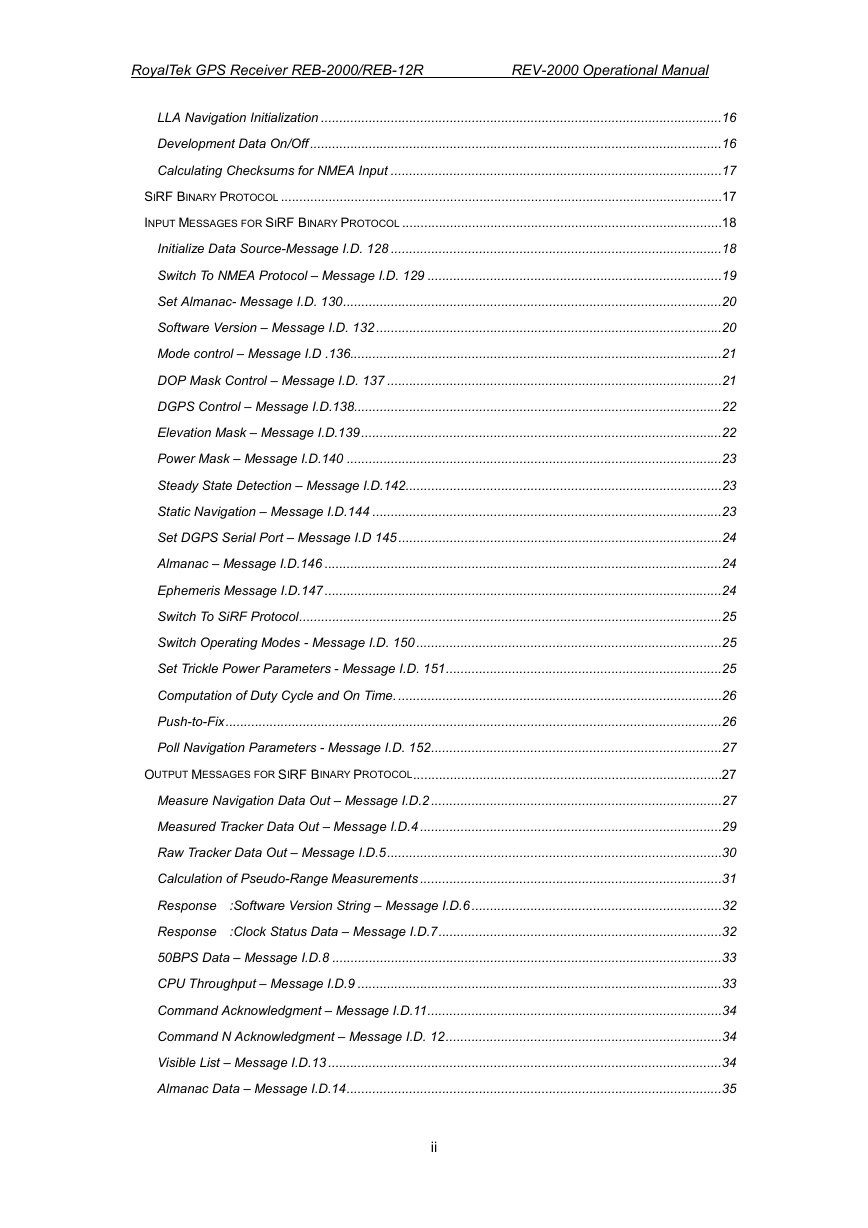
INTRODUCTION .........................................................................................................................................1
Packing list .........................................................................................................................................1
GETTING STARTED ....................................................................................................................................3
To Setup REV-2000 ...........................................................................................................................3
Setup procedure.................................................................................................................................4
TO OPERATE REV-2000 ...........................................................................................................................5
Install the SiRFDemo.exe...................................................................................................................5
To use Sirfdemo.exe ..........................................................................................................................5
To switch from NMEA to SiRF protocol ..............................................................................................7
To switch from SiRF protocol to NMEA protocol.................................................................................9
To Synchronize Protocol...................................................................................................................10
To Switch Trickle Power Parameters from SiRFDemo.exe...............................................................10
To change TricklePower parameters of REB-2100 from 12 pins interface. ......................................12
To upgrade GPS engine board program ..........................................................................................12
PRODUCT FEATURES...............................................................................................................................13
PRODUCT APPLICATIONS..........................................................................................................................14
TECHNIQUE DESCRIPTION ........................................................................................................................14
REB-2100 System Block Diagram......................................................................................................2
REB-12R Block diagram ....................................................................................................................3
Technique specifications ....................................................................................................................3
ORDERING INFORMATION ...........................................................................................................................7
ABSOLUTE MAXIMUM RATINGS ..................................................................................................................10
SOFTWARE INTERFACE ............................................................................................................................10
NMEA V2.2 Protocol ........................................................................................................................10
GGA-Global Positioning System Fixed Data....................................................................................10
GLL-Geographic Position – Latitude/Longitude................................................................................11
GSA-GNSS DOP and Active Satellites ............................................................................................11
GSV-GNSS Satellites in View ..........................................................................................................12
RMC-Recommended Minimum Specific GNSS Data.......................................................................12
VTG-Course Over Ground and Ground Speed ................................................................................13
SIRF PROPRIETARY NMEA INPUT MESSAGES..........................................................................................13
SIRF NMEA INPUT MESSAGES...............................................................................................................14
Set Serial Port ..................................................................................................................................14
LLA Navigation Initialization .............................................................................................................14
Set DGPS Port .................................................................................................................................15
Query/Rate Control ..........................................................................................................................15
i
�
RoyalTek GPS Receiver REB-2000/REB-12R REV-2000 Operational Manual
LLA Navigation Initialization .............................................................................................................16
Development Data On/Off ................................................................................................................16
Calculating Checksums for NMEA Input ..........................................................................................17
SIRF BINARY PROTOCOL ........................................................................................................................17
INPUT MESSAGES FOR SIRF BINARY PROTOCOL .......................................................................................18
Initialize Data Source-Message I.D. 128 ..........................................................................................18
Switch To NMEA Protocol – Message I.D. 129 ................................................................................19
Set Almanac- Message I.D. 130.......................................................................................................20
Software Version – Message I.D. 132 ..............................................................................................20
Mode control – Message I.D .136.....................................................................................................21
DOP Mask Control – Message I.D. 137 ...........................................................................................21
DGPS Control – Message I.D.138....................................................................................................22
Elevation Mask – Message I.D.139..................................................................................................22
Power Mask – Message I.D.140 ......................................................................................................23
Steady State Detection – Message I.D.142......................................................................................23
Static Navigation – Message I.D.144 ...............................................................................................23
Set DGPS Serial Port – Message I.D 145........................................................................................24
Almanac – Message I.D.146 ............................................................................................................24
Ephemeris Message I.D.147 ............................................................................................................24
Switch To SiRF Protocol...................................................................................................................25
Switch Operating Modes - Message I.D. 150...................................................................................25
Set Trickle Power Parameters - Message I.D. 151...........................................................................25
Computation of Duty Cycle and On Time. ........................................................................................26
Push-to-Fix.......................................................................................................................................26
Poll Navigation Parameters - Message I.D. 152...............................................................................27
OUTPUT MESSAGES FOR SIRF BINARY PROTOCOL....................................................................................27
Measure Navigation Data Out – Message I.D.2 ...............................................................................27
Measured Tracker Data Out – Message I.D.4 ..................................................................................29
Raw Tracker Data Out – Message I.D.5...........................................................................................30
Calculation of Pseudo-Range Measurements ..................................................................................31
Response :Software Version String – Message I.D.6 ....................................................................32
Response :Clock Status Data – Message I.D.7.............................................................................32
50BPS Data – Message I.D.8 ..........................................................................................................33
CPU Throughput – Message I.D.9 ...................................................................................................33
Command Acknowledgment – Message I.D.11................................................................................34
Command N Acknowledgment – Message I.D. 12...........................................................................34
Visible List – Message I.D.13 ...........................................................................................................34
Almanac Data – Message I.D.14......................................................................................................35
ii
�
RoyalTek GPS Receiver REB-2000/REB-12R REV-2000 Operational Manual
Set Ephemeris – Message I.D.254...................................................................................................35
Development Data – Message I.D.255.............................................................................................35
iii
�
RoyalTek GPS Receiver REB-2000/REB-12R REV-2000 Operational Manual
Introduction
REV-2000 is an evaluation kit for RoyalTek GPS engine board series, REB-12R2/R6/ REB-2000/
REB-2001.It is convenient to test the GPS performance,cold start / warm start / hot start,position
update and so on by using the REV-2000. REV-2000 helps you understand the operation and
performance of Royaltek’s GPS engine boards in a couple of minutes. It can also provide you design
the OEM products that use RoyalTek’s GPS engine boards.
Packing list
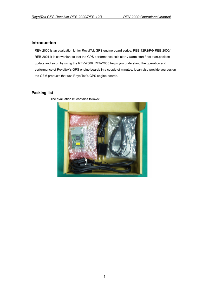
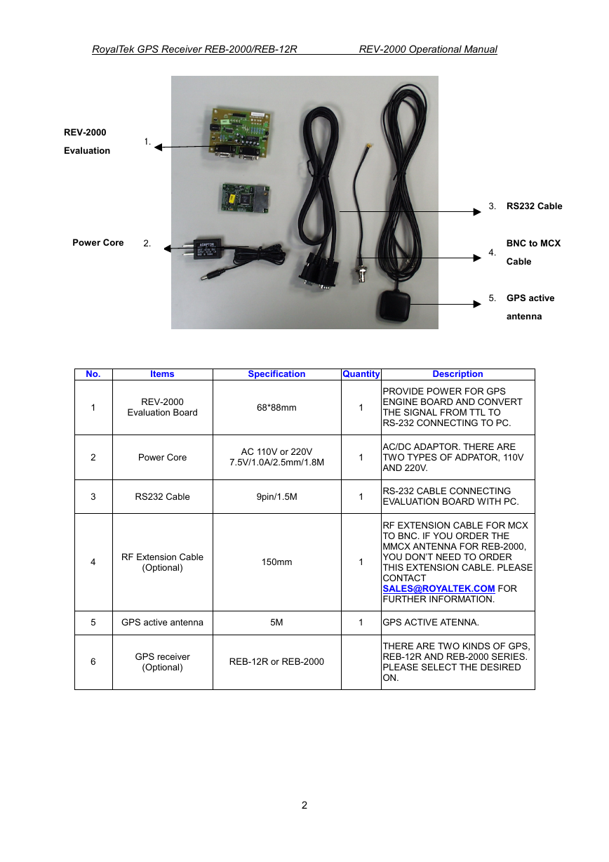
The evaluation kit contains follows:
1
�
RoyalTek GPS Receiver REB-2000/REB-12R REV-2000 Operational Manual
Specification
68*88mm
3.
RS232 Cable
4.
5.
BNC to MCX
Cable
GPS active
antenna
Quantity
Description
1
1
1
1
PROVIDE POWER FOR GPS
ENGINE BOARD AND CONVERT
THE SIGNAL FROM TTL TO
RS-232 CONNECTING TO PC.
AC/DC ADAPTOR. THERE ARE
TWO TYPES OF ADPATOR, 110V
AND 220V.
RS-232 CABLE CONNECTING
EVALUATION BOARD WITH PC.
RF EXTENSION CABLE FOR MCX
TO BNC. IF YOU ORDER THE
MMCX ANTENNA FOR REB-2000,
YOU DON’T NEED TO ORDER
THIS EXTENSION CABLE. PLEASE
CONTACT
SALES@ROYALTEK.COM FOR
FURTHER INFORMATION.
REV-2000
Evaluation Board
Power Core
AC 110V or 220V
7.5V/1.0A/2.5mm/1.8M
RS232 Cable
9pin/1.5M
RF Extension Cable
(Optional)
150mm
REV-2000
Evaluation
1.
Power Core
2.
No.
Items
1
2
3
4
5
6
GPS active antenna
5M
1
GPS ACTIVE ATENNA.
GPS receiver
(Optional)
REB-12R or REB-2000
THERE ARE TWO KINDS OF GPS,
REB-12R AND REB-2000 SERIES.
PLEASE SELECT THE DESIRED
ON.
2
�
RoyalTek GPS Receiver REB-2000/REB-12R REV-2000 Operational Manual
Getting started
To Setup REV-2000
The interface of REV-2000 is shown as follows:
VBT
Backup battery input 2.5V ~ 3.1V
DC input
+6.5V ~
Power
Power mode
jumper J1
Open: +5V
Short: +3.3V
P1 NMEA / SiRF protocol
port
Connecting to PC/Laptop
Power mode jumper J1
The power core of REV-2000 is 110V AC/ 7.5V
DC adaptor. It converts the 110 AC to DC.
RoyalTek can also provide you 220V AC power
core. Beware of the AC power of your office
and tell RoyalTek’s sales person for preparing
the correct power code for you.
REV-2000 provides 3 power modes on borad,
3.3V and 5V. JP1: Open for +5V, Short for 3.3V.
The 3.3V is for REB-2000/ REB-2100. The 5V
is for REB-12R2.
BOOT jumper
The BOOT jumper is for program upgrade. It
shall be kept open for normal operation. When
the BOOT is short, the GPS engine board is
3
CON20 REB-12R2 connector
CON12 REB-2000/REB-2100
RESET switch
BOOT jumper
Open: Normal operation
Short: Program upgrade
P2 DGPS RTCM-104 port
waiting for program upgrade and output
nothing when running SiRF demo program.
Please refer the program upgrade session for
program update.
DC input
The power input can be DC input instead of
using AC power core. The input range of the
DC input is from 6.5V ~ 12V. We suggest
you use +7.5V as the DC input.
Reset
It is used for external reset.
VBT
This is for RAM backup power of
REB-2000/REB-2100 and REB-12R2. The
�
RoyalTek GPS Receiver REB-2000/REB-12R REV-2000 Operational Manual
input range is from 2.5V ~ 3.1V DC.
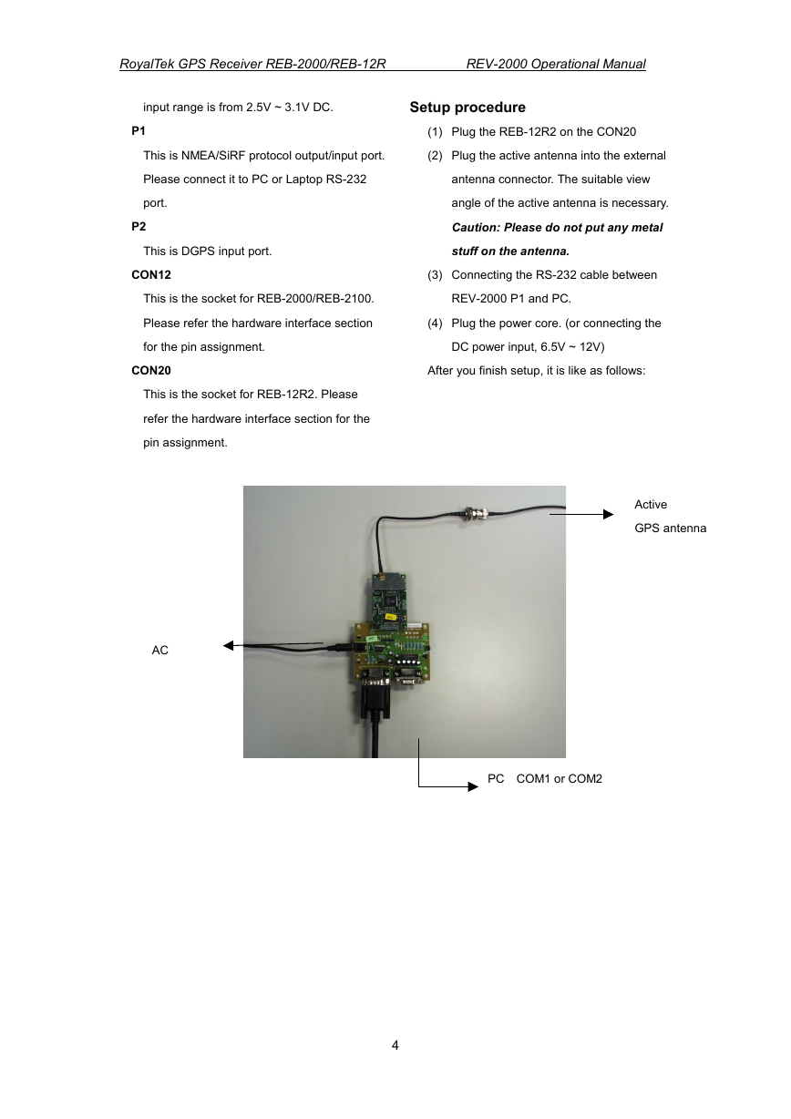
Setup procedure
P1
This is NMEA/SiRF protocol output/input port.
Please connect it to PC or Laptop RS-232
port.
P2
This is DGPS input port.
CON12
This is the socket for REB-2000/REB-2100.
Please refer the hardware interface section
for the pin assignment.
CON20
This is the socket for REB-12R2. Please
refer the hardware interface section for the
pin assignment.
(1) Plug the REB-12R2 on the CON20
(2) Plug the active antenna into the external
antenna connector. The suitable view
angle of the active antenna is necessary.
Caution: Please do not put any metal
stuff on the antenna.
(3) Connecting the RS-232 cable between
REV-2000 P1 and PC.
(4) Plug the power core. (or connecting the
DC power input, 6.5V ~ 12V)
After you finish setup, it is like as follows:
AC
Active
GPS antenna
PC COM1 or COM2
4
�




 2023年江西萍乡中考道德与法治真题及答案.doc
 2012年重庆南川中考生物真题及答案.doc
 2013年江西师范大学地理学综合及文艺理论基础考研真题.doc
 2020年四川甘孜小升初语文真题及答案I卷.doc
 2020年注册岩土工程师专业基础考试真题及答案.doc
 2023-2024学年福建省厦门市九年级上学期数学月考试题及答案.doc
 2021-2022学年辽宁省沈阳市大东区九年级上学期语文期末试题及答案.doc
 2022-2023学年北京东城区初三第一学期物理期末试卷及答案.doc
 2018上半年江西教师资格初中地理学科知识与教学能力真题及答案.doc
 2012年河北国家公务员申论考试真题及答案-省级.doc
 2020-2021学年江苏省扬州市江都区邵樊片九年级上学期数学第一次质量检测试题及答案.doc
 2022下半年黑龙江教师资格证中学综合素质真题及答案.doc