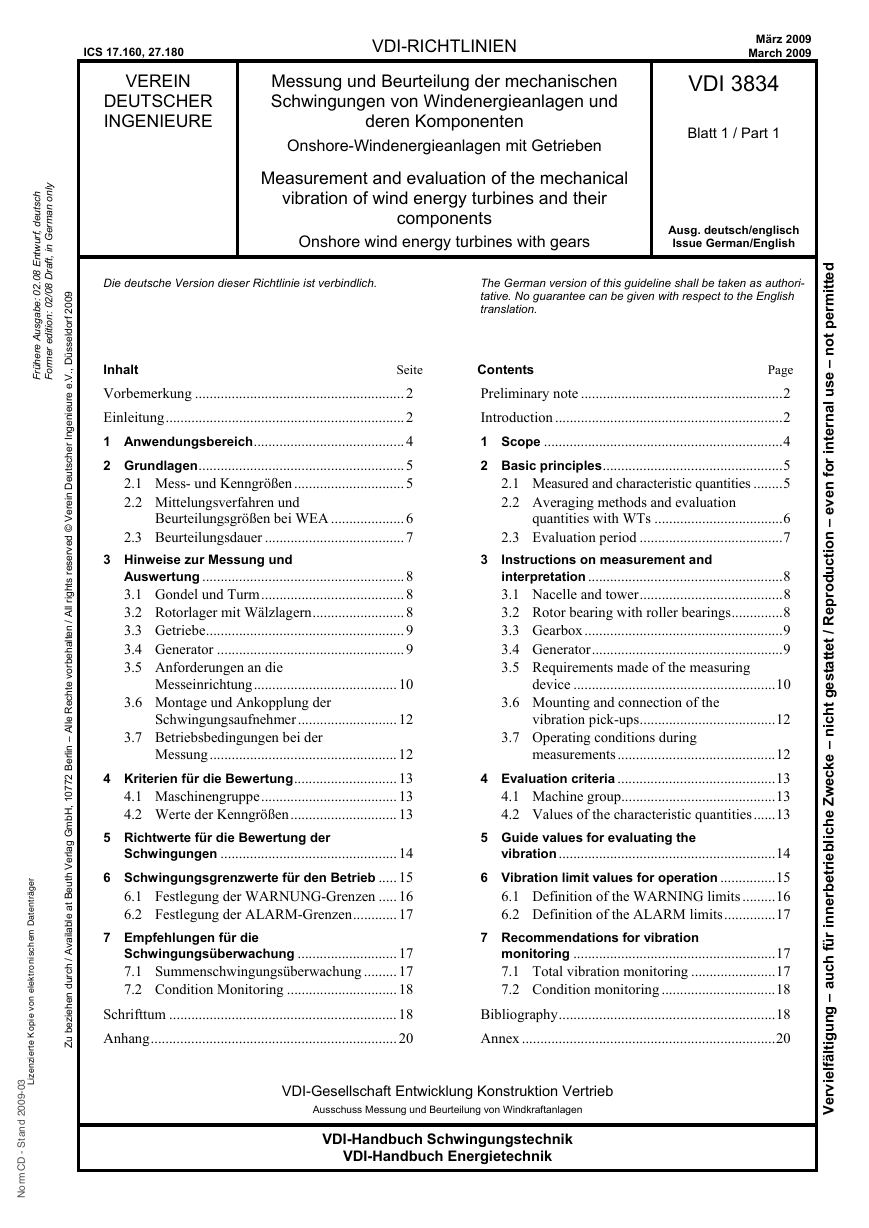
ICS 17.160, 27.180
VEREIN
DEUTSCHER
INGENIEURE
VDI-RICHTLINIEN
Messung und Beurteilung der mechanischen
Schwingungen von Windenergieanlagen und
deren Komponenten
Onshore-Windenergieanlagen mit Getrieben
Measurement and evaluation of the mechanical
vibration of wind energy turbines and their
components
Onshore wind energy turbines with gears
März 2009
March 2009
VDI 3834
Blatt 1 / Part 1
Ausg. deutsch/englisch
Issue German/English
9
0
0
2
l
f
r
o
d
e
s
s
ü
D
,
.
.
V
e
e
r
u
e
n
e
g
n
i
i
I
r
e
h
c
s
t
u
e
D
n
e
r
e
V
©
d
e
v
r
e
s
e
r
s
t
h
g
i
r
l
l
A
/
n
e
t
l
a
h
e
b
r
o
v
e
t
h
c
e
R
e
l
l
A
–
n
i
l
r
e
B
2
7
7
0
1
,
H
b
m
G
g
a
l
r
e
V
h
u
e
B
t
t
a
l
e
b
a
l
i
a
v
A
/
h
c
r
u
d
n
e
h
e
z
e
b
i
u
Z
l
y
n
o
n
a
m
r
e
G
n
i
,
t
f
a
r
D
8
0
2
0
/
:
n
o
i
t
i
d
e
r
e
m
r
o
F
h
c
s
t
u
e
d
t
,
f
r
u
w
n
E
8
0
.
2
0
:
e
b
a
g
s
u
A
e
r
e
h
ü
r
F
r
e
g
ä
r
t
n
e
t
a
D
m
e
h
c
s
n
o
r
t
k
e
e
n
o
v
l
i
i
e
p
o
K
e
t
r
e
i
z
n
e
z
i
L
3
0
-
9
0
0
2
d
n
a
t
S
-
D
C
m
r
o
N
Die deutsche Version dieser Richtlinie ist verbindlich.
The German version of this guideline shall be taken as authori-
tative. No guarantee can be given with respect to the English
translation.
Inhalt
Seite
Vorbemerkung .........................................................2
Einleitung.................................................................2
1 Anwendungsbereich.........................................4
2 Grundlagen........................................................5
2.1 Mess- und Kenngrößen ..............................5
2.2 Mittelungsverfahren und
Beurteilungsgrößen bei WEA ....................6
2.3 Beurteilungsdauer ......................................7
3 Hinweise zur Messung und
Auswertung .......................................................8
3.1 Gondel und Turm.......................................8
3.2 Rotorlager mit Wälzlagern.........................8
3.3 Getriebe......................................................9
3.4 Generator ...................................................9
3.5 Anforderungen an die
Messeinrichtung.......................................10
3.6 Montage und Ankopplung der
Schwingungsaufnehmer...........................12
3.7 Betriebsbedingungen bei der
Messung...................................................12
4 Kriterien für die Bewertung............................13
4.1 Maschinengruppe.....................................13
4.2 Werte der Kenngrößen.............................13
Contents
Page
Preliminary note .......................................................2
Introduction ..............................................................2
1 Scope .................................................................4
2 Basic principles.................................................5
2.1 Measured and characteristic quantities ........5
2.2 Averaging methods and evaluation
3
quantities with WTs ...................................6
2.3 Evaluation period .......................................7
Instructions on measurement and
interpretation .....................................................8
3.1 Nacelle and tower.......................................8
3.2 Rotor bearing with roller bearings..............8
3.3 Gearbox......................................................9
3.4 Generator....................................................9
3.5 Requirements made of the measuring
device .......................................................10
3.6 Mounting and connection of the
vibration pick-ups.....................................12
3.7 Operating conditions during
measurements...........................................12
4 Evaluation criteria ...........................................13
4.1 Machine group..........................................13
4.2 Values of the characteristic quantities......13
5 Richtwerte für die Bewertung der
Schwingungen ................................................14
6 Schwingungsgrenzwerte für den Betrieb .....15
6.1 Festlegung der WARNUNG-Grenzen .....16
6.2 Festlegung der ALARM-Grenzen............17
7 Empfehlungen für die
Schwingungsüberwachung ...........................17
7.1 Summenschwingungsüberwachung .........17
7.2 Condition Monitoring ..............................18
Schrifttum .............................................................. 18
Anhang...................................................................20
5 Guide values for evaluating the
vibration...........................................................14
6 Vibration limit values for operation ...............15
6.1 Definition of the WARNING limits .........16
6.2 Definition of the ALARM limits..............17
7 Recommendations for vibration
monitoring .......................................................17
7.1 Total vibration monitoring .......................17
7.2 Condition monitoring ...............................18
Bibliography...........................................................18
Annex .....................................................................20
VDI-Gesellschaft Entwicklung Konstruktion Vertrieb
Ausschuss Messung und Beurteilung von Windkraftanlagen
VDI-Handbuch Schwingungstechnik
VDI-Handbuch Energietechnik
d
e
t
t
i
m
r
e
p
t
o
n
–
e
s
u
l
a
n
r
e
t
n
i
r
o
f
n
e
v
e
–
n
o
i
t
c
u
d
o
r
p
e
R
i
/
t
e
t
t
a
t
s
e
g
t
h
c
n
–
e
k
c
e
w
Z
e
h
c
i
l
b
e
i
r
t
e
b
r
e
n
n
i
r
ü
f
h
c
u
a
–
g
n
u
g
i
t
l
ä
f
l
e
v
r
e
V
i
�
VDI 3834 Blatt 1 / Part 1
– 2 –
Vorbemerkung
Der Inhalt dieser Richtlinie ist entstanden unter
Beachtung der Vorgaben und Empfehlungen der
Richtlinie VDI 1000.
Alle Rechte, insbesondere das des Nachdrucks, der
Fotokopie, der elektronischen Verwendung und der
Übersetzung,
jeweils auszugsweise oder voll-
ständig, sind vorbehalten.
Die Nutzung dieser VDI-Richtlinie ist unter Wah-
rung des Urheberrechtes und unter Beachtung der
Lizenzbedingungen (www.vdi-richtlinien.de), die
in den VDI-Merkblättern geregelt sind, möglich.
Allen, die ehrenamtlich an der Erarbeitung dieser
VDI-Richtlinie mitgewirkt haben, sei gedankt.
Einleitung
Die zurzeit vorliegenden Normen zur Beurteilung
der Schwingungen von Bauwerken und Maschinen
sind auf Windenergieanlagen (WEA) wegen der
speziellen Bau- und Betriebsbedingungen nicht
anwendbar. Die Schwingungen von Turm und
Gondel einer WEA durch die Einwirkungen von
Wind oder Seegang bei Offshore-WEA, von Strö-
mungsstörungen im Turmvorstau sowie von Ei-
genschwingungen der Rotorblätter und des Bau-
werkes (Turm und Gründung) unterscheiden sich
hinsichtlich des Zeitverlaufs und der Spektren von
denen anderer Industriebauten. Die in DIN 4150-3
und in ISO 4866 erläuterten Messverfahren und
Kriterien zur Beurteilung der Schwingungen von
Bauwerken können aber als Leitfaden dienen.
Für die Komponenten in WEA (Rotorlager, Ge-
triebe und Generator) könnten die Grundnormen
DIN ISO 10816-1 und DIN ISO 7919-1 zur Mes-
sung und Bewertung der Schwingungen von Ma-
schinen herangezogen werden. Auf diesen basieren
unter
anderem DIN ISO 10816-3 und DIN
ISO 7919-3 für industrielle Maschinen aller Art.
Im Geltungsbereich von DIN ISO 10816-3 sind
aber WEA ausdrücklich ausgeschlossen. In DIN
ISO 7919-3 werden diese nicht erwähnt.
Die Kriterien in diesen Normen wären grundsätz-
lich auf die Komponenten von WEA anwendbar,
sie gelten aber dort nur für Schwingungen, die im
Maschinensatz selbst erzeugt werden und damit
direkt auf seine Bauteile einwirken. Sie gelten auch
für die Beurteilung der Schwingungsemission, das
heißt die Abstrahlung in die Umgebung eines Ma-
schinensatzes. Die Kriterien gelten aber nicht für
Schwingungen, die von externen Quellen auf die
Maschinen übertragen werden, das heißt für die
Schwingungsimmission. Bei WEA sind das die
Einwirkungen von Schwingungen des Turmes oder
Alle Rechte vorbehalten © Verein Deutscher Ingenieure e.V., Düsseldorf 2009
Preliminary note
The content of this guideline has been developed in
strict accordance with the requirements and rec-
ommendations of the guideline VDI 1000.
All rights are reserved, including those of reprint-
ing, reproduction (photocopying, micro copying),
storage in data processing systems and translation,
either of the full text or of extracts.
The use of this guideline without infringement of
copyright is permitted subject to the licensing con-
ditions specified in the VDI Notices (www.vdi-
richtlinien.de).
We wish to express our gratitude to all honorary
contributors to this guideline.
Introduction
The standards currently available for evaluating
vibration of structures and machines cannot be
applied to wind energy turbines (WT) due to the
special nature of their construction and operation.
The vibration of the tower and nacelle of a WT
caused by the effects of wind or sea swell in the
case of offshore WTs, of flow disturbances imme-
diately in front of the tower, and of the natural
vibration of the rotor blades and structure itself
(tower and foundations) differ from those of other
industrial structures with respect to the time behav-
iour and spectra of the vibration. The measuring
procedures and criteria for evaluating the vibration
of structures which are explained in DIN 4150-3
and ISO 4866 may, however, be used for guidance.
The basic standards DIN ISO 10816-1 and DIN
ISO 7919-1 dealing with the measurement and
evaluation of machine vibration could be called on
for the components of WTs (rotor bearing, gearbox
and generator). On these are based a number of
other standards, including DIN ISO 10816-3 and
DIN ISO 7919-3 for industrial machines of all
kinds. WTs are, however, expressly excluded from
the scope of application of DIN ISO 10816-3 while
DIN ISO 7919-3 does not mention them.
The criteria laid down in these standards would in
principle be applicable to WT components but in
these standards they apply only to vibration gen-
erated within the machine set itself and which
thus affect its components directly. They are also
valid for evaluating the vibration emission – in
other words, emission into the environment of a
machine set. The criteria cannot, however, be
applied to vibration transmitted to the machines
from external sources – in other words, vibration
immission. With WTs, these are the effects of
vibration of the tower or nacelle, which in the
Lizenzierte Kopie von elektronischem Datenträger
3
0
-
9
0
0
2
d
n
a
t
S
-
D
C
m
r
o
N
--`,,`,,```,,,,``,```````,,``,-`-`,,`,,`,`,,`---�
All rights reserved © Verein Deutscher Ingenieure, Düsseldorf 2009
der Gondel, die durch Wind und Seegang bei Off-
shore-WEA angeregt werden.
Wegen des großen Einflusses des Schwingungs-
pegels einer WEA auf die Beanspruchung aller
Bauteile und Komponenten und damit auf deren
Betriebszuverlässigkeit und Lebensdauer, besteht
aus der Sicht verschiedener europäischer Hersteller
und Betreiber von WEA sowie von Beratern, Ver-
sicherungen und Service-Unternehmen ein großes
Interesse an einem anerkannten Regelwerk mit
Kriterien und Empfehlungen zur Messung und
Bewertung der mechanischen Schwingungen von
WEA und deren Komponenten. Das ist die wesent-
liche Aufgabe der Richtlinienreihe VDI 3834.
Ihr Ziel ist die Vereinheitlichung der Messungen,
die Unterstützung in der Bewertung und die ver-
gleichbare Beurteilung von gemessenen Schwin-
gungen an WEA und deren Komponenten. Die
Ergebnisse der Messungen sollen bei Überschrei-
tung der festgelegten Richtwerte Hinweise auf eine
mögliche Gefährdung der entsprechenden Kompo-
nente der WEA oder der Anlage als Ganzes geben,
ohne deren Ursache im Einzelnen zu identifizieren.
Beim Unterschreiten der Richtwerte liegt zwar ein
normales, übliches Laufverhalten vor, einzelne
Schäden sind aber dennoch nicht ausgeschlossen.
Das Funktionsprinzip von WEA besteht typischer-
weise aus einem sich drehenden Rotor mit horizon-
taler Achse. Der Rotor besteht aus einer Rotornabe
mit starr oder drehbar um deren Längsachse be-
festigten Rotorblättern. Die Rotornabe ist mit dem
Triebstrang der WEA verbunden. Die Um-
wandlung der mechanischen Energie in elektrische
erfolgt durch einen Generator, dem ein Getriebe
vorgeschaltet sein kann. Diese Bauteile zur Ener-
gieumwandlung sind in der Regel in einem Ma-
schinenhaus – hier als Gondel bezeichnet – unter-
gebracht. Die Gondel ist drehbar auf einem Turm
gelagert, der in einem Fundament gegründet ist.
Die Rotorblätter und somit der Rotor sind unsym-
metrischen Anströmverhältnissen, aber auch sto-
chastischen Windgeschwindigkeitsfluktuationen
ausgesetzt. Unsymmetrische Anströmungen resul-
tieren z. B. aus Windturbulenzen, Böen, der Schräg-
anströmung des Rotors sowie aus unterschiedlicher
Windgeschwindigkeitsverteilung über die Rotor-
fläche. Neben den aerodynamischen Lasten wirken
auch Massenkräfte sowie Lasten aus den unter-
schiedlichen Betriebssituationen auf die WEA ein.
Die Überlagerung der externen Bedingungen mit
den Betriebsbedingungen, z. B. Leistung und Dreh-
zahl, unter Berücksichtigung der konstruktiven
Ausführung der WEA bzw. der einzelnen Kompo-
nenten führt zu Wechselbelastungen auf die ge-
VDI 3834 Blatt 1 / Part 1
– 3 –
case of offshore WTs are excited by wind and sea
swell.
Due to the great influence the vibration level of a
WT has on the stress of all components and thus on
their operational reliability and service lives, there
will be great interest on the part of the various
European manufacturers and operators of WTs and
also consultants, insurers and servicing companies
in having a recognized code of practice which pro-
vides criteria and recommendations regarding the
measurement and evaluation of the mechanical
vibration of WTs and their components. This is the
central task of the VDI 3834 series of guidelines.
Its aim is to standardize measurements, to assist in
their evaluation and to make possible a compara-
tive evaluation of the vibration measured in WTs
and their components. In the event of guide values
being exceeded, the results of such measurements
should enable conclusions to be drawn regarding
possible threats to the corresponding components
of the WT or to the installation as a whole but
without identifying the corresponding causes in
any detail. If guide values are not being exceeded,
running behaviour may well be normal but this
does not rule out the possibility of individual in-
stances of damage.
The working principle of WTs is typically based
on a horizontally mounted rotating rotor. The rotor
consists of a rotor hub with rotor blades which are
either mounted immovably or which can be turned
on their longitudinal axis. The rotor hub is con-
nected to the drive train of the WT. The mechani-
cal energy is converted into electrical energy by a
generator, on whose input side there may be a
gearbox. As a rule these energy conversion com-
ponents are accommodated in a machinery housing
– referred to as a nacelle. The nacelle is rotatable
mounted on bearings in the tower while the tower
itself stands on its own foundation.
The rotor blades and thus the rotor are exposed not
only to asymmetric incoming flow behaviour but
also to stochastic wind-speed fluctuations. Asym-
metric incoming flows are, for example, the result
of wind turbulence, gusts, off-axis flow into the
rotor as well as different wind-speeds distributed
over the rotor surface. In addition to aerodynamic
loads, the WT is also affected by inertial forces and
by loads resulting from different operating situa-
tions. Superimposition of the external conditions
onto the operating conditions, such as output and
speed, taking into consideration the constructive
design of the WT or its individual components,
results in alternating loading on the entire WT with
its rotor, drive train, tower and foundation and thus
Lizenzierte Kopie von elektronischem Datenträger
3
0
-
9
0
0
2
d
n
a
t
S
-
D
C
m
r
o
N
�
VDI 3834 Blatt 1 / Part 1
– 4 –
samte WEA mit Rotor, Triebstrang, Turm und
Fundament und somit zur Schwingungsanregung
an den einzelnen Bauteilen.
Triebstränge bestehen aus Baugruppen, die bauart-
bedingt und triebstrangspezifisch drehzahlabhän-
gige und drehzahlunabhängige Schwingungen
erregen. Generatoren, Getriebe und Kupplungen
zeigen hersteller- und designabhängig als einzelne
Baugruppen und im Zusammenspiel und in Ab-
hängigkeit vom Typ der Windenergieanlage ein
unterschiedliches Schwingungsverhalten. Je nach
Erreger und Anregungsbereich können auftretende
Schwingungen beispielsweise aus einer schlechten
Ausrichtung resultieren und zu Zahneingriffstößen
in der Getriebeverzahnung führen. Des Weiteren
können Resonanzschwingungen im Triebstrang
auftreten. Aus diesen Gründen muss immer die
gesamte WEA, das heißt Triebstrang mit Rotor-
blättern, Gondel und Turm betrachtet werden.
Wegen des möglicherweise großen Einflusses, den
Aufstellungsort und Art des mechanischen Trieb-
stranges auf den Schwingungspegel aller Kompo-
nenten haben, war es notwendig, die in VDI 3834
klassifizierten WEA in vier Gruppen einzuteilen:
Gruppe 1: Onshore-Anlagen mit Generatoren, die
über Getriebe mit dem Rotor gekuppelt sind
Gruppe 2: Onshore-Anlagen mit getriebelos ge-
kuppeltem Generator
Gruppe 3: Offshore-Anlagen mit Generatoren, die
über Getriebe mit dem Rotor gekuppelt sind
Gruppe 4: Offshore-Anlagen mit getriebelos ge-
kuppeltem Generator
Für jede dieser Gruppen soll in der Richtlinien
reihe VDI 3834 ein eigenes Blatt heraus gegeben
werden. Diese werden spezifische Festlegungen zu
den Kenngrößen, Messorten und Messbedingungen
enthalten, sowie Tabellen mit Richtwerten zur
Bewertung gemessener Schwingungen.
Alle Rechte vorbehalten © Verein Deutscher Ingenieure e.V., Düsseldorf 2009
to vibration excitation at the individual compo-
nents.
Drive trains consist of assemblies which, depend-
ing on their type of design and the particular drive
train, excite vibration which may or may not be
independent of speed. Depending on the manufac-
turer and design, a different vibratory behaviour is
shown by generators, gearboxes and clutches, not
only as individual assemblies but also in interac-
tion with and depending on the type of wind en-
ergy installation. Depending on the exciter and
excitation range, the occurring vibration can, for
example, result from poor alignment and lead to
gear-tooth engagement shocks in the gearbox. Fur-
thermore, resonance vibration may occur in the
drive train. For these reasons it is imperative in all
cases to take the entire WT into consideration – in
other words, the drive train with rotor blades, na-
celle and tower.
On account of the great influence which the place
of installation and type of mechanical drive train
may have on the vibration level of all components,
it has been necessary to divide the WTs dealt with
in VDI 3834 into four groups:
Group 1: Onshore installations with generators
coupled to the rotor via a gearbox
Group 2: Onshore installations with generators
coupled to the rotor without a gearbox (direct
drive)
Group 3: Offshore installations with generators
coupled to the rotor via a gearbox
Group 4: Offshore installations with generators
coupled to the rotor without a gearbox (direct
drive)
A separate part of the VDI 3834 series will be de-
voted to each of these types and will contain spe-
cific
information about characteristic values,
measuring positions and measurement conditions,
as well as tables with guide values for the evalua-
tion of the vibration measured.
1 Anwendungsbereich
Die Richtlinienreihe VDI 3834 gibt Hinweise zur
Messung und Beurteilung der mechanischen
Schwingungen von Windenergieanlagen und deren
Komponenten. Sie gilt für WEA mit Generator-
Nennleistungen über 100 kW und den folgenden
Bau- und Betriebsmerkmalen:
• Aufstellung auf dem Festland (onshore) oder
vor Küsten (offshore)
• Aufstellung auf Tragsystemen (Turm und Grün-
dung) aus Stahl und Beton
1 Scope
The VDI 3834 series of guidelines provides infor-
mation about the measurement and evaluation of
the mechanical vibration of wind turbines and their
components. It applies to WTs with rated generator
outputs exceeding 100 kW and the following de-
sign and operation characteristics:
• siting onshore or off the coast (offshore)
installation on supporting systems (tower and
foundation) made of steel and concrete
•
Lizenzierte Kopie von elektronischem Datenträger
3
0
-
9
0
0
2
d
n
a
t
S
-
D
C
m
r
o
N
�
All rights reserved © Verein Deutscher Ingenieure, Düsseldorf 2009
• horizontale Lagerung des Rotors mit mehreren
VDI 3834 Blatt 1 / Part 1
– 5 –
• horizontal-axis rotor with several rotor blades
Rotorblättern
Getriebe
getriebelos
art
• Rotorlager getrennt vom oder integriert im
• rotor bearing separate from or integrated into
• Antrieb der Generatoren über Getriebe oder
• generators driven via gearbox or direct driven
• Generatoren in Synchron- oder Asynchronbau-
• generators of the synchronous or asynchronous
• Generatoren mit nur einer Polzahl oder polum-
schaltbar zur Drehzahlanpassung
• Leistungsregelung durch Rotorblattverstellung
(Pitch) oder Strömungsabriss (Stall)
• generators with only a fixed pole number or
which are pole-changeable for speed adjustment
• output control by rotor blade adjustment pitch
• Ankopplung des Generators an das Netz über
• generator coupled to the power grid via con-
Umrichter oder direkt.
the gearbox
type
or stall
verter or directly.
Die vorliegende Richtlinie gilt für WEA der Grup-
pe 1. Sie enthält im Abschnitt 5 die Richtwerte für
die Bewertung der Schwingungen im stabilen Pro-
duktionsbetrieb, vorerst nur mit Nennleistungen
≤ 3 MW.
In Vorbereitung befindet sich VDI 3834 Blatt 2 für
WEA der Gruppe 2. Hierfür liegt schon eine kleine
Zahl von Messdaten vor.
Für Offshore-WEA (Gruppe 3 und Gruppe 4)
konnten noch keine Messdaten gesammelt werden.
Die Richtlinienreihe VDI 3834 gilt nicht für Ab-
nahmemessungen an den Getrieben und Generato-
ren im Herstellerprüffeld. Diese sind nach den
hierfür geltenden Normen zu beurteilen. Das sind
ISO 8579-2 und DIN EN 60034-14.
Die in Abschnitt 5 genannten Richtwerte sind nicht
zur Fehlerfrüherkennung geeignet. Die Richtlinien-
reihe VDI 3834 gilt nicht für die Bewertung von
Torsionsschwingungen des Triebstranges sowie
des Zustands der Wälzlager und Zahnräder. Hin-
weise zur Messung und Beurteilung des Körper-
schalls von Wälzlagern finden sich in der Richt-
linie VDI 3832. Informationen zur Art und Aus-
führung von Condition Monitoring Systemen für
WEA werden in Abschnitt 7.2 gegeben.
2 Grundlagen
2.1 Mess- und Kenngrößen
Kenngrößen sind nach vorgeschriebenen Verfahren
aus dem gemessenen Rohsignal (Messgröße) ge-
bildete charakteristische Größen. Die Messungen
sind an vorgeschriebenen Messorten, in fest-
gelegten Messrichtungen und unter definierten
Betriebsbedingungen auszuführen. Zu den Ver-
fahren gehören die notwendige Signalverarbeitung,
die Filterung und Mittelung sowie die Bildung von
Kennwerten oder Kennfunktionen und letztlich die
Anzeige. Dieser Prozess wird auch als Kennwert-
bildung bezeichnet.
The present guideline applies to Group 1 WTs. In
Section 5 will be found the guide values for evalu-
ating vibration in the stable generating range, but
for the time being only for nominal outputs of
≤ 3 MW or less.
VDI 3834 Part 2 for Group 2 WTs is currently in
preparation and a small amount of measured data is
already available.
It has not yet been possible to collect any data for
offshore WTs (Group 3 and Group 4).
The VDI 3834 guideline series does not apply to
acceptance measurements at gearboxes and genera-
tors in the manufacturer's test facilities. These should
be assessed on the basis of the appropriate standards,
namely, ISO 8579-2 and DIN EN 60034-14.
The guide values given in Section 5 are not suit-
able for the early detection of faults. The VDI 3834
series of guidelines does not apply to the evalua-
tion of torsional vibration in the drive train nor to
the state of the roller bearings and gears. Notes on
the measurement and evaluation of structure-borne
sound with roller bearings may be found in guide-
line VDI 3832. Information on the type and im-
plementation of condition monitoring systems for
WTs is given in Section 7.2.
2 Basic principles
2.1 Measured and characteristic quantities
Characteristic quantities are formed by means of
prescribed procedures from the raw measured sig-
nal (measured quantity). Measurements must be
carried out at prescribed measuring positions, in
specified measuring directions and under defined
operating conditions. Procedures include the nec-
essary signal processing, filtering and averaging as
well as the formation of characteristic values or
characteristic functions, and finally displaying the
results. This process is also referred to as the for-
mation of characteristic quantities.
Lizenzierte Kopie von elektronischem Datenträger
3
0
-
9
0
0
2
d
n
a
t
S
-
D
C
m
r
o
N
�
VDI 3834 Blatt 1 / Part 1
– 6 –
Allgemeine Informationen über die im Folgenden
genannten Mess- und Kenngrößen sowie über die
üblichen Verfahren und Geräte zur Messung und
Analyse von Maschinenschwingungen werden in
der Richtlinie VDI 3839 Blatt 1 gegeben.
Für die Beurteilung der Schwingungseinwirkungen
auf WEA und deren Komponenten müssen die in
anderen Normen oder Richtlinien zur Beurteilung
der Schwingungen von Maschinen genannten Ver-
fahren zum Bilden der Kenngrößen ergänzt werden.
2.2 Mittelungsverfahren und Beurteilungs-
größen bei WEA
Alle Rechte vorbehalten © Verein Deutscher Ingenieure e.V., Düsseldorf 2009
information
is provided
General
in guideline
VDI 3839 Part 1 regarding the measured and char-
acteristic quantities mentioned below as well as
about the procedures and instruments normally used
for measuring and analyzing machine vibration.
For the evaluation of the effects of vibration on
WTs and their components, the machine vibration
evaluation procedures mentioned in other standards
or guidelines need to be supplemented to enable
formation of the characteristic quantities.
2.2 Averaging methods and evaluation
quantities with WTs
Die speziellen Betriebsbedingungen von WEA, die
ständige Änderung von Stärke und Anström-
richtung des Windes und eventuell die zusätzlichen
Anregungen aus dem Wellengang bei Offshore-
Anlagen führen zu ständig wechselnden Schwin-
gungsanregungen und als Folge zu kurzzeitigen
Änderungen der Messwerte mit häufig starken
Amplitudensprüngen. Nur selten gibt es für längere
Perioden so stabile Betriebsbedingungen, wie sie in
den verschiedenen Teilen von DIN ISO 10816 und
DIN ISO 7919 für die Beurteilung des Schwin-
gungszustandes gefordert werden.
Es ist bei WEA daher unbedingt notwendig, die
gemessenen Werte zum Bilden der Kenngrößen
über vorgegebene Zeiträume zu mitteln, um die
Schwankungen auszugleichen. Für den Vergleich
mit den Richtwerten in Abschnitt 6 ist Voraus-
setzung, dass auch die dort aufgeführten Werte auf
vergleichbar gemittelten Daten beruhen.
Als Mittelungsverfahren soll bei WEA die „ener-
gieäquivalente Mittelung“ gewählt werden. Dabei
wird z. B. aus dem Zeitverlauf der Beschleunigung
eine Beurteilungsbeschleunigung aw0 definiert. Sie
kennzeichnet die Gesamtbelastung während einer zu
vereinbarenden Beurteilungsdauer T0 (Intervall-
Effektivwert) und ergibt sich aus dem energieäqui-
valenten Mittelwert der gemessenen frequenz-
begrenzten Beschleunigung aw(t) nach
The special operating conditions applicable to
WTs, the continual changes in the strength and
direction of the wind and possibly too the addi-
tional excitations arising from the sea swell in the
case of offshore installations result in continually
changing vibration excitations and, as a conse-
quence of this, short-term changes in measured
values with jumps in amplitude which are often
considerable. Only seldom do such stable condi-
tions occur for extended periods as are specified in
the different parts of DIN ISO 10816 and DIN
ISO 7919 for the evaluation of the vibration state.
For this reason, with WTs it is absolutely essential
when forming the characteristic quantities to aver-
age the measured values over specified time peri-
ods so as to compensate for the fluctuations. Be-
fore any comparison can be made with the guide
values in Section 6, even the values listed there
must be based on comparably averaged data.
The averaging method chosen for WTs should be
“energy-equivalent averaging”. Here, for example,
from the elapsed time for acceleration an evalua-
tion acceleration aw0 is defined. It characterizes the
total loading over an evaluation period T0 (the in-
terval RMS value, which is to be defined) and is
obtained from the energy-equivalent mean value of
the measured frequency-limited acceleration aw(t)
according to
a
eff
w0
=
0
1 T
∫
T
0
0
2
ta
w
t
d)(
(1)
a
rms
w0
=
0
1 T
∫
T
0
0
2
ta
w
t
d)(
(1)
wobei aw(t) die gemessene, frequenzbegrenzte
Beschleunigung als Funktion der Zeit ist. Entspre-
chend lässt sich die Beurteilungsgeschwindigkeit
vw0 berechnen. Die Frequenzbegrenzung erfolgt für
die Arbeitsfrequenzbereiche nach Abschnitt 3.
Anmerkung: Die hier beschriebene Art der Mittelung der
gemessenen Beschleunigung entspricht der in ISO 2631-1 und
VDI 2057 Blatt 3 vorgeschriebenen, wenn z. B. die Langzeit-
einwirkung von Schwingungen beurteilt werden muss. Das
Mittelungsverfahren gleicht formal dem in DIN EN ISO 8041
und DIN 45662 beschriebenen zur Bildung des Intervall-
where aw(t) is the measured, frequency-limited
acceleration as a function of time. The evaluation
vibration velocity vw0 can be calculated in a similar
way. For the operating frequency ranges the fre-
quency limitation has to be chosen from Section 3.
Note: The method described here for averaging the measured
acceleration corresponds to the one prescribed in ISO 2631-1
and VDI 2057 Part 3, when, for example, the long-term effect
of vibration needs to be evaluated. The averaging method will
be formally the same as the one described in DIN EN
ISO 8041 and DIN 45662 for obtaining the time-averaged
Lizenzierte Kopie von elektronischem Datenträger
3
0
-
9
0
0
2
d
n
a
t
S
-
D
C
m
r
o
N
�
All rights reserved © Verein Deutscher Ingenieure, Düsseldorf 2009
Effektivwerts, wenn für das dort definierte Zeitintervall T die
Beurteilungsdauer T0 eingesetzt wird.
2.3 Beurteilungsdauer
Die Beurteilungsdauer T0 hängt von der Art und
dem Zeitverlauf der Einwirkungen durch Wind und
Wellengang (bei Offshore-Anlagen) auf die Ge-
samtanlage und ihre Komponenten und der Be-
urteilungsgröße ab. Sie muss so lang sein, dass die
in Abschnitt 3.7 spezifizierten Betriebszustände
voll erfasst werden.
Für die aerodynamisch angeregten Schwingungen
der Gondeln, Türme und Komponenten mit Fre-
quenzen zwischen 0,1 Hz und 10 Hz und relativ
großen Beschleunigungen und Geschwindigkeiten
soll die Beurteilungsdauer 10 min betragen. Damit
können auch die Schwingungskomponenten mit
Frequenzen um oder unter 1 Hz, das heißt mit der
Drehfrequenz des Rotors, zuverlässig gemessen
und analysiert werden.
An den Getrieben und Generatoren können zusätz-
lich
bauartbedingten
Schwingungen mit Frequenzen zwischen 10 Hz
und höher als 1000 Hz auftreten. Wenn hier nur
diese höherfrequenten Anteile im Spektrum be-
urteilt werden sollen, genügen kürzere Beurtei-
lungsdauern von z. B. 1 min.
Es kann notwendig werden, die Beurteilungsdauer
von 10 min in kürzere, von der Messeinrichtung
oder den Betriebsbedingungen bestimmte Zeit-
abschnitten Te von mindestens 1 min Dauer zu
unterteilen. Wenn in diesen Zeitabschnitten die
Schwingungsanregungen deutlich wechseln, erge-
ben
unterschiedliche
energieäquivalente Mittelwerte awe.
Die Beurteilungsbeschleunigung für die verein-
barte Beurteilungsdauer ergibt sich dann aus
charakteristischen,
jeweils
sich
die
VDI 3834 Blatt 1 / Part 1
– 7 –
RMS value when the evaluation period T0 is used for the time
interval T defined there.
2.3 Evaluation period
The evaluation period T0 depends not only on the
nature and time history of the effects on the entire
installation and its components caused by wind and
sea swell (in the case of offshore installations) but
also on the evaluation quantity. The evaluation
period must be long enough to fully cover the op-
erating modes specified in Section 3.7.
For the aerodynamically excited vibration of the
nacelles, towers and components with frequencies
between 0,1 Hz and 10 Hz and relatively high ac-
celerations and velocities, the evaluation period
should be set at 10 min. In this way even those
vibration components with frequencies around or
below 1 Hz – in other words, at the rotational fre-
quency of the rotor – can be reliably measured and
analyzed.
At gearboxes and generators, characteristic design-
related vibration with frequencies between 10 Hz
and more than 1000 Hz can occur in addition. If
evaluation is only to be concerned with these
higher-frequency parts of the spectrum, shorter
evaluation periods of, for example, 1 min will suf-
fice.
It may be necessary to subdivide the 10 min
evaluation period into shorter time periods Te as
determined by the measuring device or the operat-
ing conditions. These shorter time periods should
not be less than 1 min. If the vibration excitations
change markedly during these time periods, this
will yield in each case different energy-equivalent
mean values awe.
The evaluation acceleration for the agreed evalua-
tion period is thus obtained from
a
weff
=
1
T
0
n
∑
e
1
=
a
2
e T
⋅
e
rms
(2)
a
wrms
=
1
T
0
n
∑
e
1
=
a
2
e T
⋅
e
rms
(2)
n
e
1
=
=
eT
T
0
mit ∑
Die gewählte Beurteilungsdauer sowie die verwen-
deten Arbeitsfrequenzbereiche sind in allen Mess-
protokollen oder Berichten zusammen mit den
jeweiligen Beurteilungsgrößen zu nennen.
n
e
1
=
=
eT
T
0
where ∑
The evaluation period selected and the used operat-
ing frequency ranges should be indicated in all test
records or reports, together with the evaluation
quantities concerned.
3
0
-
9
0
0
2
d
n
a
t
S
-
D
C
m
r
o
N
Lizenzierte Kopie von elektronischem Datenträger
�
VDI 3834 Blatt 1 / Part 1
– 8 –
3 Hinweise zur Messung und
Auswertung
Für die WEA als Bauwerk und ihre Komponenten
müssen unterschiedliche Kenngrößen, Messorte
und Messrichtungen festgelegt werden, wobei in
allen Fällen sowohl die Schwingbeschleunigung
als auch die Schwinggeschwindigkeit zu messen
sind:
3.1 Gondel und Turm
Kenngrößen
• Beurteilungsbeschleunigung in m/s2
• Beurteilungsgeschwindigkeit in mm/s
• beide gebildet während der in Abschnitt 2.3
spezifizierten Beurteilungsdauer im Arbeits-
frequenzbereich ≤ 0,1 Hz bis 10 Hz
• Die untere Grenzfrequenz sollte unter der Rot-
ordrehfrequenz liegen.
Messorte
•
in der Gondel beiderseits vom Fuß des Haupt-
lagers und im hinteren Ende beiderseits vom
Generator bzw. vom Maschinenträger
• am Turm unterhalb des Azimutlagers
Messrichtungen
• axial (Richtung der Rotorwelle)
• horizontal (quer zur Rotorwelle)
• vertikal
3.2 Rotorlager mit Wälzlagern
Kenngrößen
• Die Beurteilungsbeschleunigung wird gebildet
während der in Abschnitt 2.3 spezifizierten
Beurteilungsdauer im Arbeitsfrequenzbereich
≤ 0,1 Hz bis 10 Hz.
• Die untere Grenzfrequenz sollte unter der Rot-
ordrehfrequenz liegen.
Alle Rechte vorbehalten © Verein Deutscher Ingenieure e.V., Düsseldorf 2009
3
Instructions on measurement and
interpretation
Different characteristic quantities, measuring posi-
tions and measuring directions must be specified
for the WTs as a structure and for its components.
In all cases the vibration acceleration and the vi-
bration speed have to be measured accordingly:
3.1 Nacelle and tower
Characteristic quantities
• evaluation acceleration in m/s²
• evaluation velocity in mm/s
• both formed during the evaluation period speci-
fied in Section 2.3, in the operating frequency
range ≤ 0,1 Hz to 10 Hz
• The lower limit frequency should be below the
rotor speed frequency.
Measuring positions
•
in the nacelle on both sides of the mounting of
the main bearing and in the rear end on both
sides of the generator or mainframe
• on the tower below the yaw bearing
Measuring directions
• axial (direction of the rotor shaft)
• horizontal (transversely to the rotor shaft)
• vertical
3.2 Rotor bearing with roller bearings
Characteristic quantities
• The evaluation acceleration is formed during
the evaluation period specified in Section 2.3,
in the operating frequency range ≤ 0,1 Hz to
10 Hz.
• The lower limit frequency should be below the
rotor speed frequency.
• Beurteilungsgeschwindigkeit, gebildet im Ar-
beitsfrequenzbereich 10 Hz bis 1000 Hz
• evaluation velocity, formed in the operating
frequency range 10 Hz to 1000 Hz
Messorte
• Bei zwei separaten Rotorlagern liegen die
Messorte an beiden Lagergehäusen, bei Drei-
punktlagerung am Gehäuse des vorderen La-
gers.
• Bild A1 und Bild A2 im Anhang zeigen bei-
spielhaft die Messorte am Lager eines Rotors
mit Dreipunktlagerung.
Messrichtungen
• axial (Richtung der Rotorwelle)
• horizontal (quer zur Rotorwelle)
• vertikal
Measuring positions
• With two separate rotor bearings the measuring
positions will be on both bearing housings, in
the case of three-point bearings on the housing
of the front bearing.
• Figure A1 and Figure A2 in the Annex show by
way of example the measuring positions on the
bearing of a rotor with a three-point bearing.
Measuring directions
• axial (direction of the rotor shaft)
• horizontal (transversely to the rotor shaft)
• vertical
Lizenzierte Kopie von elektronischem Datenträger
3
0
-
9
0
0
2
d
n
a
t
S
-
D
C
m
r
o
N
�



 2023年江西萍乡中考道德与法治真题及答案.doc
 2012年重庆南川中考生物真题及答案.doc
 2013年江西师范大学地理学综合及文艺理论基础考研真题.doc
 2020年四川甘孜小升初语文真题及答案I卷.doc
 2020年注册岩土工程师专业基础考试真题及答案.doc
 2023-2024学年福建省厦门市九年级上学期数学月考试题及答案.doc
 2021-2022学年辽宁省沈阳市大东区九年级上学期语文期末试题及答案.doc
 2022-2023学年北京东城区初三第一学期物理期末试卷及答案.doc
 2018上半年江西教师资格初中地理学科知识与教学能力真题及答案.doc
 2012年河北国家公务员申论考试真题及答案-省级.doc
 2020-2021学年江苏省扬州市江都区邵樊片九年级上学期数学第一次质量检测试题及答案.doc
 2022下半年黑龙江教师资格证中学综合素质真题及答案.doc