logo资料库

MATLAB官方串口教程中文版.pdf

第1页 / 共67页
第2页 / 共67页
第3页 / 共67页
第4页 / 共67页
第5页 / 共67页
第6页 / 共67页
第7页 / 共67页
第8页 / 共67页
资料共67页,剩余部分请下载后查看
大家好
如何使用
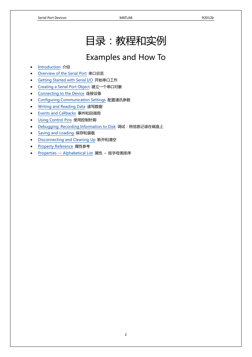
目录:教程和实例
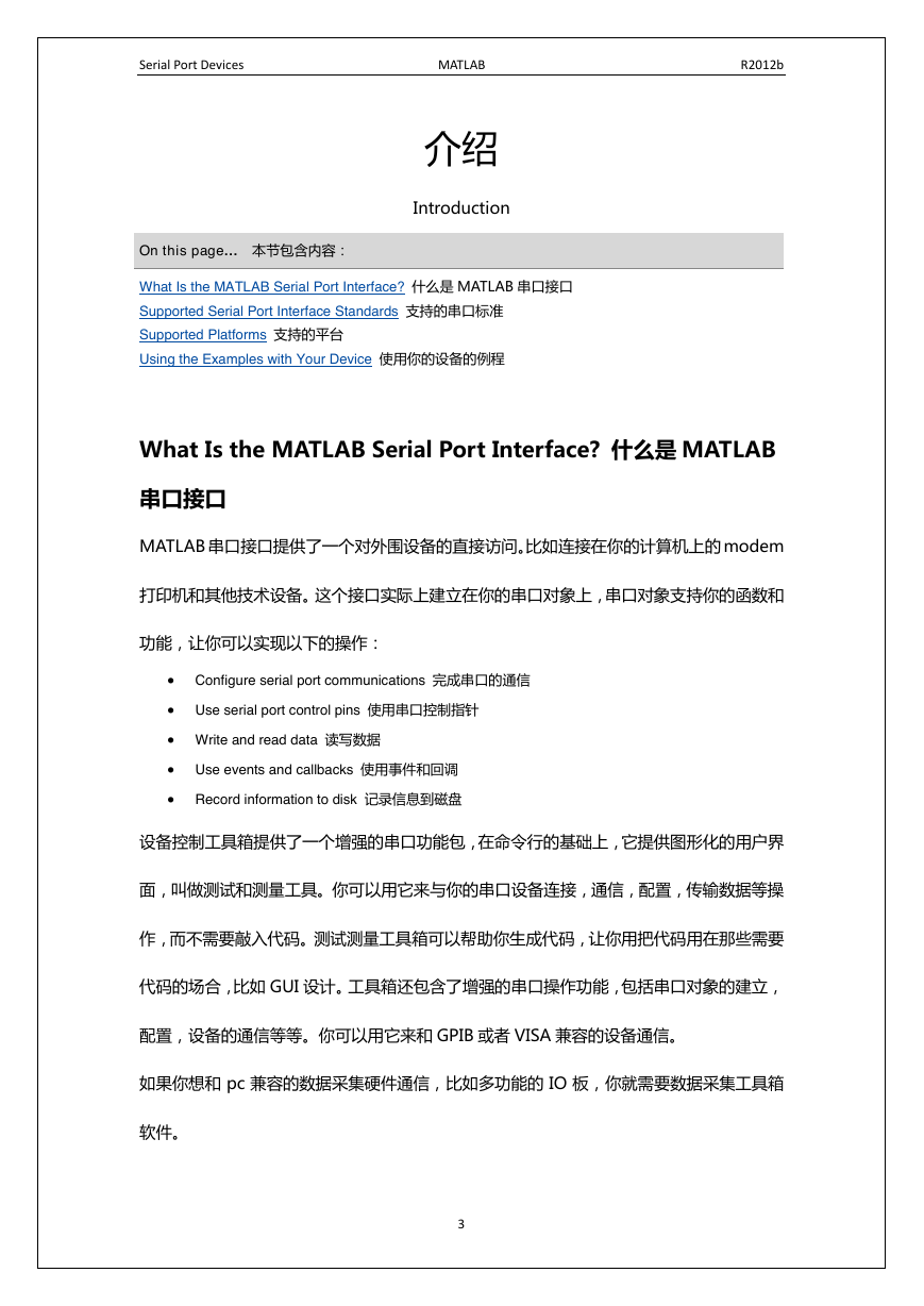
介绍
What Is the MATLAB Serial Port Interface? 什么是MATLAB串口接口
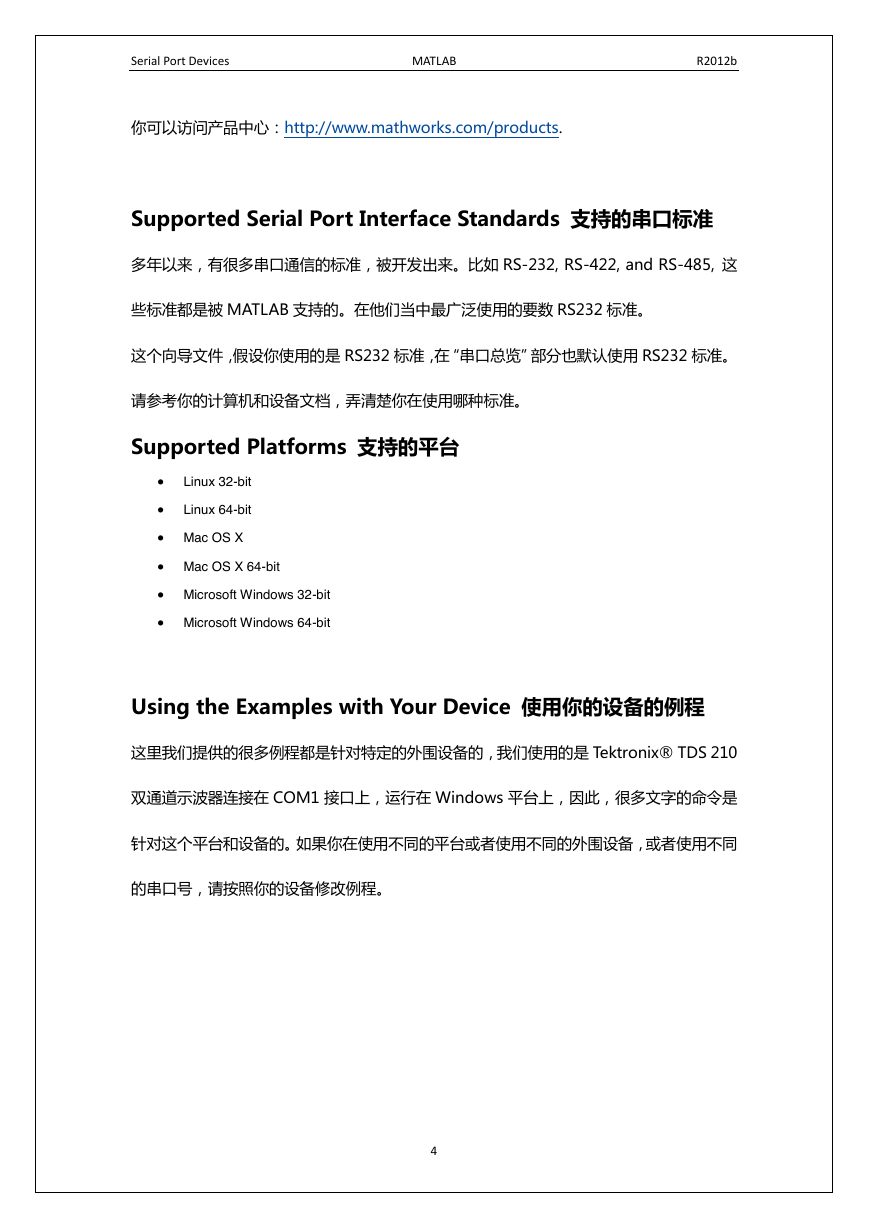
Supported Serial Port Interface Standards 支持的串口标准
Supported Platforms 支持的平台
Using the Examples with Your Device 使用你的设备的例程
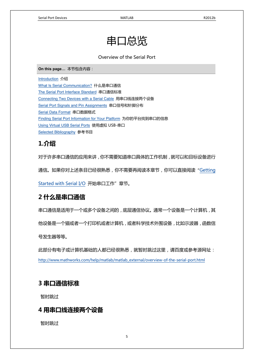
串口总览
1.介绍
2什么是串口通信
3串口通信标准
4用串口线连接两个设备
5串口信号和针脚分布
Signal States
The Data Pins
The Control Pins
6串口数据格式
7为你的平台找到串口的信息
8使用虚拟USB-串口 转接器
9参考书目
开始串口工作
Example: Getting Started 例程:开始
The Serial Port Session 串口对象会话
Configuring and Returning Properties 配置和返回属性
建立一个串口对象
1.串口对象概览
连接设备
配置通讯参数
读写数据
Before You Begin 开始之前
Example — Introduction to Writing and Reading Data 读写数据例程
Controlling Access to the MATLAB Command Line 对MATLAB命令行的访问控制
Writing Data 写数据
Reading Data 读数据
Example — Writing and Reading Text Data 例程:写读文字数据
Example — Parsing Input Data Using textscan 用textscan解析输入数据
Example — Reading Binary Data 读二进制数据
事件和回调用
Introduction 介绍
Example — Introduction to Events and Callbacks 例程,事件和回调介绍
Event Types and Callback Properties 事件类型和回调属性
Break-Interrupt Event 断裂中断事件
Bytes-Available Event 字节可用事件
Error Event 错误事件
Output-Empty Event 空输出事件
当输出缓存被清空时,空输出事件发生。
Pin Status Event 针脚状态事件
Timer Event 时间事件
Responding To Event Information 事件信息的回馈
The AbsTime Field
The Pin Field
The PinValue Field
The Message Field
Creating and Executing Callback Functions 建立和执行回调函数
Enabling Callback Functions After They Error 错误发生后重新使能回调函数
Example — Using Events and Callbacks 例程,使用事件和回调
使用控制针脚
Properties of Serial Port Control Pins 串口控制指针的属性
Signaling the Presence of Connected Devices 存在连接设备的信号
Controlling the Flow of Data: Handshaking 控制数据流:握手
调试:将信息记录在磁盘上
Introduction 介绍
Recording Properties 记录属性
Example: Introduction to Recording Information 例程:记录信息的介绍
Creating Multiple Record Files 建立多个记录文件
Specifying a Filename 分配文件名
The Record File Format 记录文件的格式
保存和装载
Using save and load 使用保存和装载
Using Serial Port Objects on Different Platforms 在不同平台上使用串口对象
断开和清空
Disconnecting a Serial Port Object 断开串口对象连接
Cleaning Up the MATLAB Environment 清空MATLAB环境
属性参考
The Property Reference Page Format 属性参考页格式
Serial Port Object Properties 串口对象属性
属性 – 按字母表排序
MATLAB-Serial Port Devices MATLAB® 串口相关功能教程
Serial Port Devices MATLAB R2012b 大家好 本文档是对 MathWorks 串口教程的翻译, 目的在于帮助大家学习 Matlab 串口设备。 教程包含以下 14 个部分,部分链接会直接指向 MathWorks 来源网页,请尽量适应英文。 水平有限,如有错误粗陋,请不吝指正。谢谢! 教程来源:http://www.mathworks.com/help/matlab/serial-port-devices.html DSP Lab of Northeastern University Dec, 2012 Boston, USA 如何使用 • 如果您是从零基础开始,既不了解 MATLAB 也从来没有用过串口通信,请在阅读本文档 之前,先学习 MATLAB 基础知识和串口通信基础知识。 • 如果您已经具备串口和 MATLAB 的使用经验,想通过学习本文档来实现 MATLAB 对串口 数据收发控制功能,请从“Getting Started with Serial I/O 开始串口工作”开始阅读。 • 如果您已经具备 MATLAB 串口基本开发能力,建议从“Events and Callbacks 事件和回 调用”开始阅读。 • 您可以点击“on this page…本节包含的内容”框内的链接访问对应的英文原文。 1
Serial Port Devices MATLAB R2012b 目录:教程和实例 Examples and How To  Introduction 介绍  Overview of the Serial Port 串口总览  Getting Started with Serial I/O 开始串口工作  Creating a Serial Port Object 建立一个串口对象  Connecting to the Device 连接设备  Configuring Communication Settings 配置通讯参数  Writing and Reading Data 读写数据  Events and Callbacks 事件和回调用  Using Control Pins 使用控制针脚  Debugging: Recording Information to Disk 调试:将信息记录在磁盘上  Saving and Loading 保存和装载  Disconnecting and Cleaning Up 断开和清空  Property Reference 属性参考  Properties — Alphabetical List 属性 – 按字母表排序 2
Serial Port Devices MATLAB R2012b 介绍 Introduction On this page… 本节包含内容: What Is the MATLAB Serial Port Interface? 什么是 MATLAB 串口接口 Supported Serial Port Interface Standards 支持的串口标准 Supported Platforms 支持的平台 Using the Examples with Your Device 使用你的设备的例程 What Is the MATLAB Serial Port Interface? 什么是 MATLAB 串口接口 MATLAB 串口接口提供了一个对外围设备的直接访问。比如连接在你的计算机上的 modem 打印机和其他技术设备。这个接口实际上建立在你的串口对象上,串口对象支持你的函数和 功能,让你可以实现以下的操作:  Configure serial port communications 完成串口的通信  Use serial port control pins 使用串口控制指针  Write and read data 读写数据  Use events and callbacks 使用事件和回调  Record information to disk 记录信息到磁盘 设备控制工具箱提供了一个增强的串口功能包,在命令行的基础上,它提供图形化的用户界 面,叫做测试和测量工具。你可以用它来与你的串口设备连接,通信,配置,传输数据等操 作,而不需要敲入代码。测试测量工具箱可以帮助你生成代码,让你用把代码用在那些需要 代码的场合,比如 GUI 设计。工具箱还包含了增强的串口操作功能,包括串口对象的建立, 配置,设备的通信等等。你可以用它来和 GPIB 或者 VISA 兼容的设备通信。 如果你想和 pc 兼容的数据采集硬件通信,比如多功能的 IO 板,你就需要数据采集工具箱 软件。 3
Serial Port Devices MATLAB R2012b 你可以访问产品中心:http://www.mathworks.com/products. Supported Serial Port Interface Standards 支持的串口标准 多年以来,有很多串口通信的标准,被开发出来。比如 RS-232, RS-422, and RS-485, 这 些标准都是被 MATLAB 支持的。在他们当中最广泛使用的要数 RS232 标准。 这个向导文件,假设你使用的是 RS232 标准,在“串口总览”部分也默认使用 RS232 标准。 请参考你的计算机和设备文档,弄清楚你在使用哪种标准。 Supported Platforms 支持的平台   Linux 32-bit Linux 64-bit  Mac OS X  Mac OS X 64-bit  Microsoft Windows 32-bit  Microsoft Windows 64-bit Using the Examples with Your Device 使用你的设备的例程 这里我们提供的很多例程都是针对特定的外围设备的,我们使用的是 Tektronix® TDS 210 双通道示波器连接在 COM1 接口上,运行在 Windows 平台上,因此,很多文字的命令是 针对这个平台和设备的。如果你在使用不同的平台或者使用不同的外围设备,或者使用不同 的串口号,请按照你的设备修改例程。 4
Serial Port Devices MATLAB R2012b 串口总览 Overview of the Serial Port On this page… 本节包含内容: Introduction 介绍 What Is Serial Communication? 什么是串口通信 The Serial Port Interface Standard 串口通信标准 Connecting Two Devices with a Serial Cable 用串口线连接两个设备 Serial Port Signals and Pin Assignments 串口信号和针脚分布 Serial Data Format 串口数据格式 Finding Serial Port Information for Your Platform 为你的平台找到串口的信息 Using Virtual USB Serial Ports 使用虚拟 USB-串口 Selected Bibliography 参考书目 1.介绍 对于许多串口通信的应用来讲,你不需要知道串口具体的工作机制,就可以和目标设备进行 通信。如果你对上述条目已经很熟悉,你不需要再阅读本章节,你可以直接阅读 ”Getting Started with Serial I/O 开始串口工作”章节。 2 什么是串口通信 串口通信是适用于一个或多个设备之间的,底层通信协议。通常一个设备是一个计算机,其 他设备是一个猫或者一个打印机或者计算机,或者科学技术外围设备,比如示波器,函数信 号发生器等等。 此部分有电子或计算机基础的人都已经很熟悉,就暂时跳过这里,请百度或参考源网址: http://www.mathworks.com/help/matlab/matlab_external/overview-of-the-serial-port.html 3 串口通信标准 暂时跳过 4 用串口线连接两个设备 暂时跳过 5
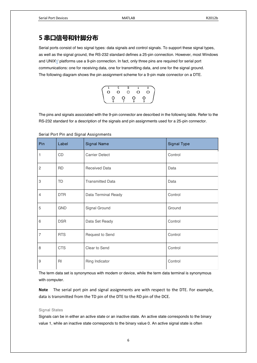
Serial Port Devices MATLAB R2012b 5 串口信号和针脚分布 Serial ports consist of two signal types: data signals and control signals. To support these signal types, as well as the signal ground, the RS-232 standard defines a 25-pin connection. However, most Windows and UNIX[1] platforms use a 9-pin connection. In fact, only three pins are required for serial port communications: one for receiving data, one for transmitting data, and one for the signal ground. The following diagram shows the pin assignment scheme for a 9-pin male connector on a DTE. The pins and signals associated with the 9-pin connector are described in the following table. Refer to the RS-232 standard for a description of the signals and pin assignments used for a 25-pin connector. Serial Port Pin and Signal Assignments Pin Label Signal Name 1 2 3 4 5 6 7 8 9 CD RD TD Carrier Detect Received Data Transmitted Data DTR Data Terminal Ready GND Signal Ground DSR Data Set Ready RTS Request to Send CTS Clear to Send RI Ring Indicator Signal Type Control Data Data Control Ground Control Control Control Control The term data set is synonymous with modem or device, while the term data terminal is synonymous with computer. Note The serial port pin and signal assignments are with respect to the DTE. For example, data is transmitted from the TD pin of the DTE to the RD pin of the DCE. Signal States Signals can be in either an active state or an inactive state. An active state corresponds to the binary value 1, while an inactive state corresponds to the binary value 0. An active signal state is often 6
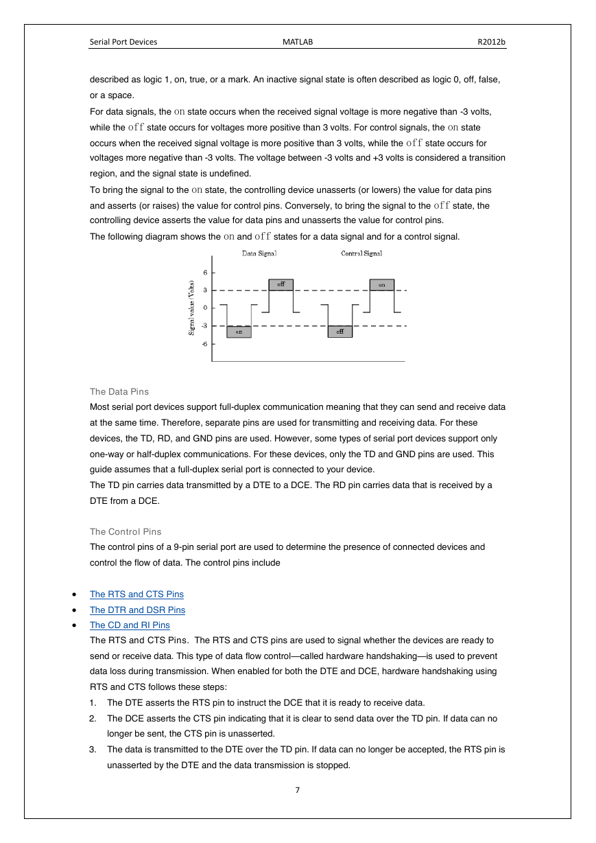
Serial Port Devices MATLAB R2012b described as logic 1, on, true, or a mark. An inactive signal state is often described as logic 0, off, false, or a space. For data signals, the on state occurs when the received signal voltage is more negative than -3 volts, while the off state occurs for voltages more positive than 3 volts. For control signals, the on state occurs when the received signal voltage is more positive than 3 volts, while the off state occurs for voltages more negative than -3 volts. The voltage between -3 volts and +3 volts is considered a transition region, and the signal state is undefined. To bring the signal to the on state, the controlling device unasserts (or lowers) the value for data pins and asserts (or raises) the value for control pins. Conversely, to bring the signal to the off state, the controlling device asserts the value for data pins and unasserts the value for control pins. The following diagram shows the on and off states for a data signal and for a control signal. The Data Pins Most serial port devices support full-duplex communication meaning that they can send and receive data at the same time. Therefore, separate pins are used for transmitting and receiving data. For these devices, the TD, RD, and GND pins are used. However, some types of serial port devices support only one-way or half-duplex communications. For these devices, only the TD and GND pins are used. This guide assumes that a full-duplex serial port is connected to your device. The TD pin carries data transmitted by a DTE to a DCE. The RD pin carries data that is received by a DTE from a DCE. The Control Pins The control pins of a 9-pin serial port are used to determine the presence of connected devices and control the flow of data. The control pins include  The RTS and CTS Pins  The DTR and DSR Pins  The CD and RI Pins The RTS and CTS Pins. The RTS and CTS pins are used to signal whether the devices are ready to send or receive data. This type of data flow control—called hardware handshaking—is used to prevent data loss during transmission. When enabled for both the DTE and DCE, hardware handshaking using RTS and CTS follows these steps: 1. The DTE asserts the RTS pin to instruct the DCE that it is ready to receive data. 2. The DCE asserts the CTS pin indicating that it is clear to send data over the TD pin. If data can no longer be sent, the CTS pin is unasserted. 3. The data is transmitted to the DTE over the TD pin. If data can no longer be accepted, the RTS pin is unasserted by the DTE and the data transmission is stopped. 7
分享到:
收藏