POV-Ray 与 Diamond 3 联用作图简介
第一节 POV-Ray 基本知识
POV-Ray,全名是 Persistence of Vision Raytracer,是一个使用光
线跟踪绘制三维图像的开放源代码免费软件。很多漂亮的图片就是由
POV-ray 来制作的。
本文的主要目的在于介绍如何利用 Diamond 软件联合 POV-Ray
画图,我们不可能将所有的功能加以介绍。本节简要介绍一下。
1.坐标系统
POV-Ray 是基于 Ray-tracing 的渲染软件,学习它的第一个事情
便是认识其坐标系统。
2. POV-Ray 文件的基本构成
�
和很多计算机语言一样,文件格式中有很多属于专用语言,这些
文字在程序中往往表现为彩色。一个基本的 POV-Ray 文件有如下几
个部分:一些头文件、摄像机定义、场景物体定义、灯光定义。
a. 头文件,常用的包括:
#include "colors.inc" // 定义基本颜色
#include "shapes.inc" // 定义基本形状物体
#include "textures.inc" // 定义一些物体属性
注://后面的文字是注释,不参与程序运行。
b. 摄像机位置和观察方向
当用 POV-Ray 的标记语言来表示一个摄像机的时候,我们可以这
location <0, 2, -3> //(大家可以想象摄像机在坐标中的位置)
look_at <0, -1, 2> //(摄像机的位置确定后,还要让镜头对着某个方向)
up x*1 //(up 和 right 定义了纵横视口比例)
right y*1
样来写 :
camera {
}
正规写法如下:
camera {
location <0.0, 2.0, -3.0>
look_at <0.0, -1.0, 2.0>
right x*image_width/image_height
}
c. 主要物体
比如我们要在<0, 0, 0>位置(原点)放置一个半径为 2 黄色的球
体可以表示为(注意{}总是成对出现,color 是系统默认关键字,黄
色若想成为关键字,被默认为黄色,应首字母大写):
sphere {
<0, 0, 0>, 2
texture {
pigment {color Yellow} }
}
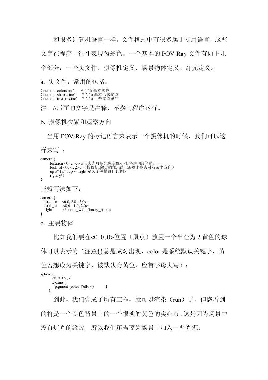
到此,我们完成了所有工作,就可以渲染(run)了,但您看到
的将是一个黑色背景上的一个很淡的黄色的实心圆。这是因为场景中
没有灯光的缘故,所以我们还需要为场景中加入一些光源:
�
light_source { <2, 4, -3> color White},再渲染一次,得到的就是一个
有明暗效果的球体了。
光源的位置很重要,为了看到较亮的图片,一般将光源置于物体
位置与您的位置之间,也就是说,您看到的大多数光源坐标的 z 值是
负的,结构越复杂越庞大,z 值也越大,比如 Diamond 常用的数值是
<100,100,-100>等
3. 场景主体的移动和转动
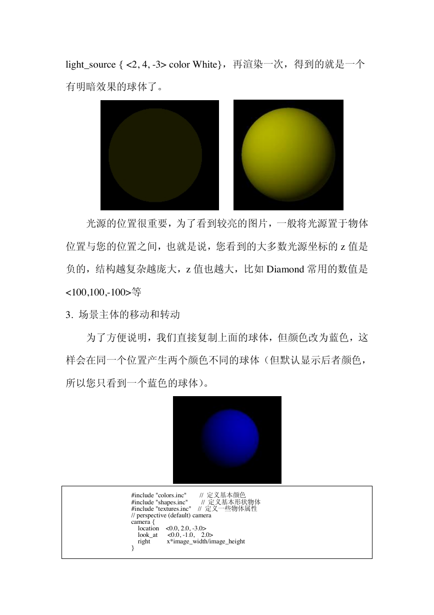
为了方便说明,我们直接复制上面的球体,但颜色改为蓝色,这
样会在同一个位置产生两个颜色不同的球体(但默认显示后者颜色,
所以您只看到一个蓝色的球体)。
#include "colors.inc" // 定义基本颜色
#include "shapes.inc" // 定义基本形状物体
#include "textures.inc" // 定义一些物体属性
// perspective (default) camera
camera {
location <0.0, 2.0, -3.0>
look_at <0.0, -1.0, 2.0>
right x*image_width/image_height
}
�
sphere {
<0, 0, 0>, 1
texture {
pigment {color Yellow} }
}
sphere {
<0, 0, 0>, 1
texture {
pigment {color Blue}
}
}
light_source { <2, 4, -3> color White}
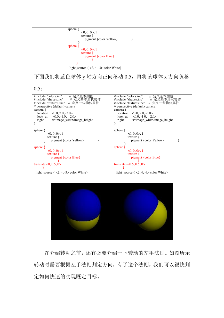
下面我们将蓝色球体 y 轴方向正向移动 0.5,再将该球体 x 方向负移
0.5:
#include "colors.inc" // 定义基本颜色
#include "shapes.inc" // 定义基本形状物体
#include "textures.inc" // 定义一些物体属性
// perspective (default) camera
camera {
location <0.0, 2.0, -3.0>
look_at <0.0, -1.0, 2.0>
right x*image_width/image_height
}
sphere {
<0, 0, 0>, 1
texture {
pigment {color Yellow} }
}
sphere {
<0, 0, 0>, 1
texture {
pigment {color Blue}
}
translate <0, 0.5, 0>
}
light_source { <2, 4, -3> color White}
#include "colors.inc" // 定义基本颜色
#include "shapes.inc" // 定义基本形状物体
#include "textures.inc" // 定义一些物体属性
// perspective (default) camera
camera {
location <0.0, 2.0, -3.0>
look_at <0.0, -1.0, 2.0>
right x*image_width/image_height
}
sphere {
<0, 0, 0>, 1
texture {
pigment {color Yellow} }
}
sphere {
<0, 0, 0>, 1
texture {
pigment {color Blue}
}
translate <-0.5, 0.5, 0>
}
light_source { <2, 4, -3> color White}
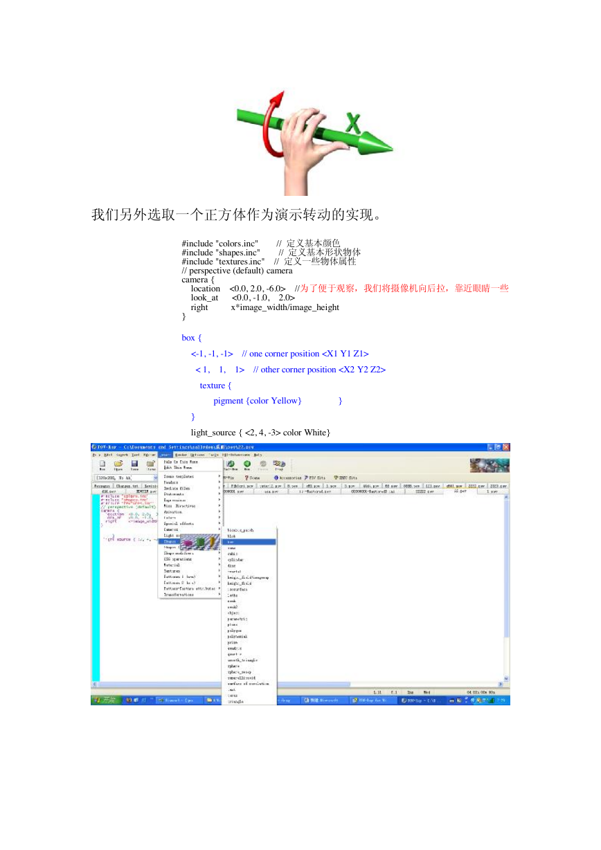
在介绍转动之前,还有必要介绍一下转动的左手法则。如图所示
转动时需要根据左手法则判定方向,有了这个法则,我们可以很快判
定如何快速的实现既定目标。
�
我们另外选取一个正方体作为演示转动的实现。
#include "colors.inc" // 定义基本颜色
#include "shapes.inc" // 定义基本形状物体
#include "textures.inc" // 定义一些物体属性
// perspective (default) camera
camera {
location <0.0, 2.0, -6.0> // 为了便于观察,我们将摄像机向后拉,靠近眼睛一些
look_at <0.0, -1.0, 2.0>
right x*image_width/image_height
}
box {
<-1, -1, -1> // one corner position
< 1, 1, 1> // other corner position
texture {
pigment {color Yellow} }
}
light_source { <2, 4, -3> color White}
�
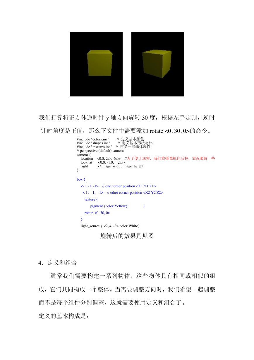
我们打算将正方体逆时针 y 轴方向旋转 30 度,根据左手定则,逆时
针时角度是正值,那么下文件中需要添加 rotate <0, 30, 0>的命令。
#include "colors.inc" // 定义基本颜色
#include "shapes.inc" // 定义基本形状物体
#include "textures.inc" // 定义一些物体属性
// perspective (default) camera
camera {
location <0.0, 2.0, -6.0> // 为了便于观察,我们将摄像机向后拉,靠近眼睛一些
look_at <0.0, -1.0, 2.0>
right x*image_width/image_height
}
box {
<-1, -1, -1> // one corner position
< 1, 1, 1> // other corner position
texture {
pigment {color Yellow} }
rotate <0, 30, 0>
}
light_source { <2, 4, -3> color White}
旋转后的效果是见图
4.定义和组合
通常我们需要构建一系列物体,这些物体具有相同或相似的组
成,它们共同构成一个整体。当需要调整方向时,我们希望一起调整
而不是每个组件分别调整,这就需要使用定义和组合了。
定义的基本构成是:
�
#declare a = xxx {}
组合的基本构成包括两部分:
命名组合:#declare b = union {
objecet {}
object {}
……..}
描述组合 object {b ……}
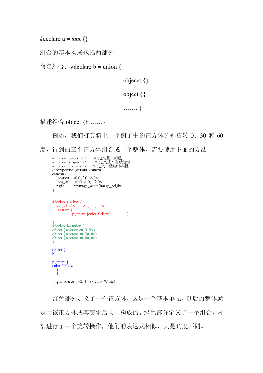
例如,我们打算将上一个例子中的正方体分别旋转 0、30 和 60
度,得到的三个正方体组合成一个整体,需要使用下面的方法:
#include "colors.inc" // 定义基本颜色
#include "shapes.inc" // 定义基本形状物体
#include "textures.inc" // 定义一些物体属性
// perspective (default) camera
camera {
location <0.0, 2.0, -6.0>
look_at <0.0, -1.0, 2.0>
right x*image_width/image_height
}
#declare a = box {
<-1, -1, -1> < 1, 1, 1>
texture {
pigment {color Yellow} }
}
#declare b= union {
object { a rotate <0, 0, 0>}
object { a rotate <0, 30, 0>}
object { a rotate <0, 60, 0>}
}
object {
b
pigment {
color Yellow
}
}
light_source { <2, 4, -3> color White}
红色部分定义了一个正方体,这是一个基本单元,以后的整体就
是由该正方体或其变化后共同构成的。绿色部分定义了一个组合,内
部进行了三个旋转操作,他们的表达式相似,只是角度不同。
�
在表述完组合后,又对组合进行描述,可以定义颜色等等,比如
为了方便观察我们还可以对组合进行旋转(x 轴正向 15 度):
object {
b
pigment {
color Yellow
}
rotate <-15, 0, 0>
}
light_source { <2, 4, -3> color White}
5.分辨率问题
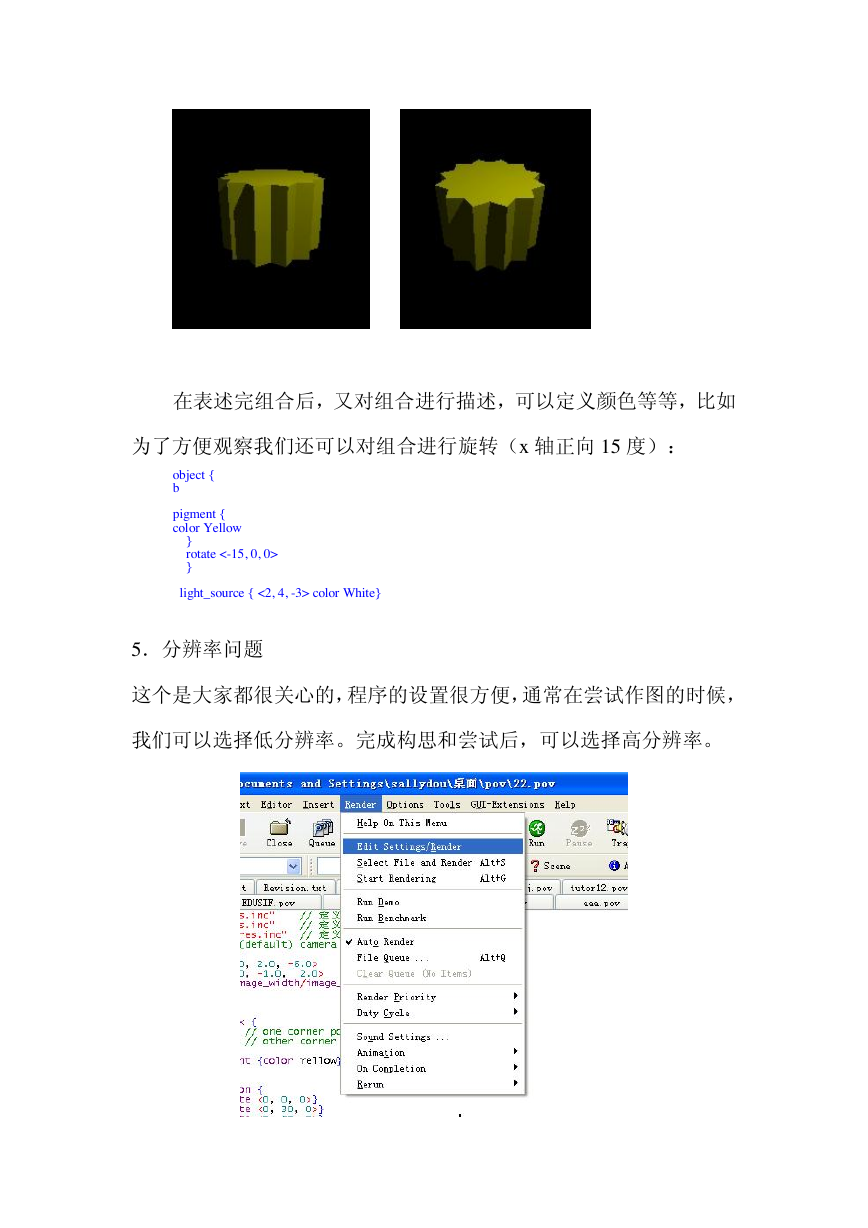
这个是大家都很关心的,程序的设置很方便,通常在尝试作图的时候,
我们可以选择低分辨率。完成构思和尝试后,可以选择高分辨率。
�



 2023年江西萍乡中考道德与法治真题及答案.doc
 2012年重庆南川中考生物真题及答案.doc
 2013年江西师范大学地理学综合及文艺理论基础考研真题.doc
 2020年四川甘孜小升初语文真题及答案I卷.doc
 2020年注册岩土工程师专业基础考试真题及答案.doc
 2023-2024学年福建省厦门市九年级上学期数学月考试题及答案.doc
 2021-2022学年辽宁省沈阳市大东区九年级上学期语文期末试题及答案.doc
 2022-2023学年北京东城区初三第一学期物理期末试卷及答案.doc
 2018上半年江西教师资格初中地理学科知识与教学能力真题及答案.doc
 2012年河北国家公务员申论考试真题及答案-省级.doc
 2020-2021学年江苏省扬州市江都区邵樊片九年级上学期数学第一次质量检测试题及答案.doc
 2022下半年黑龙江教师资格证中学综合素质真题及答案.doc