logo资料库

Soc Designer教程.pdf

第1页 / 共134页
第2页 / 共134页
第3页 / 共134页
第4页 / 共134页
第5页 / 共134页
第6页 / 共134页
第7页 / 共134页
第8页 / 共134页
资料共134页,剩余部分请下载后查看
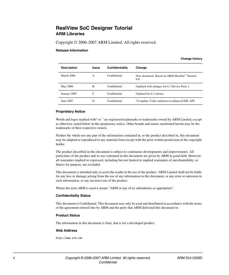
RealView SoC Designer Tutorial ARM Libraries
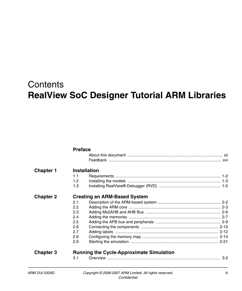
Contents
List of Tables
List of Figures
Preface
About this document
Intended audience
Organization
Terminology
Further reading
Feedback
Feedback on SoC Designer
Feedback on this document
Installation
1.1 Requirements
1.2 Installing the models
1.3 Installing RealView Debugger (RVD)
Creating an ARM-Based System
2.1 Description of the ARM-based system
2.2 Adding the ARM core
2.3 Adding Mx2AHB and AHB Bus
2.4 Adding the memories
2.5 Adding the APB bus and peripherals
2.6 Connecting the components
2.7 Adding labels
2.8 Configuring the memory map
2.9 Starting the simulation
Running the Cycle-Approximate Simulation
3.1 Overview
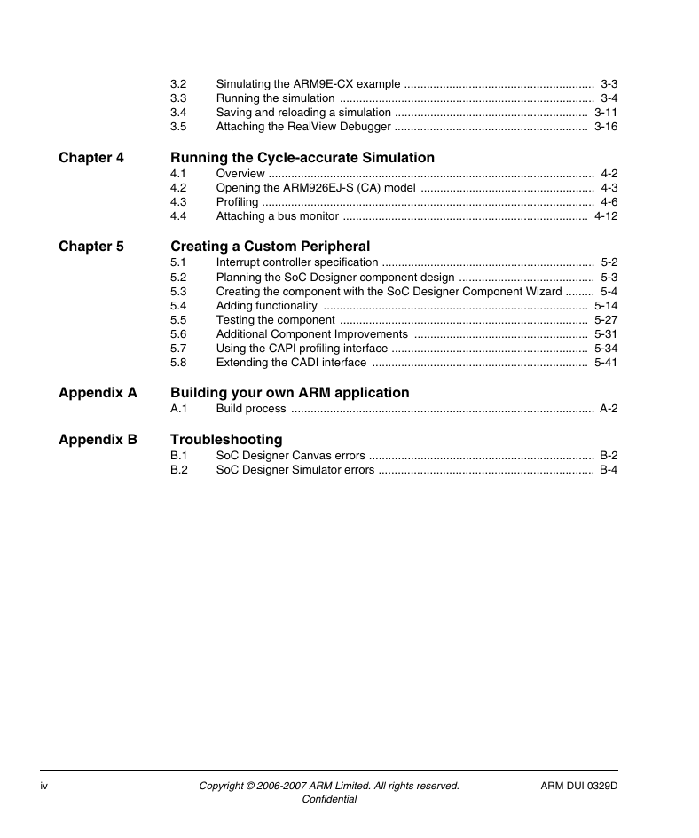
3.2 Simulating the ARM9E-CX example
3.3 Running the simulation
3.3.1 Setting a breakpoint
3.3.2 Viewing a signal
3.3.3 Viewing code
3.3.4 Viewing data memory
3.4 Saving and reloading a simulation
3.4.1 Saving a simulation
3.4.2 Opening a saved simulation file
3.5 Attaching the RealView Debugger
Running the Cycle-accurate Simulation
4.1 Overview
4.2 Opening the ARM926EJ-S (CA) model
4.2.1 Basic functionality
4.3 Profiling
4.4 Attaching a bus monitor
Creating a Custom Peripheral
5.1 Interrupt controller specification
5.1.1 Features
5.1.2 Memory-mapped registers
5.2 Planning the SoC Designer component design
5.3 Creating the component with the SoC Designer Component Wizard
5.3.1 Component name and location
5.3.2 Component attributes
5.3.3 Add port definitions
5.3.4 Add parameter definitions
5.3.5 Add CADI registers and memory regions
5.3.6 Generating the component files
5.4 Adding functionality
5.4.1 Variables for the communicate and update phases
5.4.2 Memory mapping
5.4.3 Private variables
5.4.4 Debug access to registers
5.4.5 The interrupt request signal
5.4.6 Reset behavior
5.4.7 Update Phase
5.4.8 Driving the irq output signal
5.4.9 Save and restore
5.4.10 Compiling the finished component code
5.5 Testing the component
5.5.1 Creating a test environment
5.5.2 Writing the script
5.5.3 Configuring the IRQ_ENABLE register
5.5.4 Driving the interrupt sources
5.5.5 Saving the script files
5.5.6 Running the test system
5.6 Additional Component Improvements
5.6.1 SetAddressRegions
5.6.2 GetMappingContraints
5.6.3 Remove unused functions
5.6.4 Cleaning up the ISRC port
5.7 Using the CAPI profiling interface
5.7.1 Implementing the CAPI interface class
5.7.2 Using the CAPI interface in the component
5.7.3 Recording profiling events
5.7.4 Displaying the profiling results
5.8 Extending the CADI interface
5.8.1 Define the new registers
5.8.2 Specifying read/write access behavior
Building your own ARM application
A.1 Build process
A.1.1 Source files
A.1.2 Linking the application
A.1.3 Loading the application
Troubleshooting
B.1 SoC Designer Canvas errors
B.1.1 Library not found
B.1.2 Overlapping regions
B.1.3 Port not connected
B.2 SoC Designer Simulator errors
B.2.1 Cycle counter advances, but no activity in system
RealView® SoC Designer Tutorial v7.0 ARM Libraries Confidential Copyright © 2006-2007 ARM Limited. All rights reserved. ARM DUI 0329D
RealView SoC Designer Tutorial ARM Libraries Copyright © 2006-2007 ARM Limited. All rights reserved. Release Information Change history Description Issue Confidentiality Change March 2006 May 2006 January 2007 June 2007 A B C D Confidential New document. Based on ARM MaxSim™ Tutorial 6.0. Confidential Updated with changes for 6.1 Service Pack 1. Confidential Updated for 6.2 release. Confidential 7.0 update. Code conforms to enhanced ESL API. Proprietary Notice Words and logos marked with® or ™ are registered trademarks or trademarks owned by ARM Limited, except as otherwise stated below in this proprietary notice. Other brands and names mentioned herein may be the trademarks of their respective owners. Neither the whole nor any part of the information contained in, or the product described in, this document may be adapted or reproduced in any material form except with the prior written permission of the copyright holder. The product described in this document is subject to continuous developments and improvements. All particulars of the product and its use contained in this document are given by ARM in good faith. However, all warranties implied or expressed, including but not limited to implied warranties of merchantability, or fitness for purpose, are excluded. This document is intended only to assist the reader in the use of the product. ARM Limited shall not be liable for any loss or damage arising from the use of any information in this document, or any error or omission in such information, or any incorrect use of the product. Where the term ARM is used it means “ARM or any of its subsidiaries as appropriate”. Confidentiality Status This document is Confidential. This document may only be used and distributed in accordance with the terms of the agreement entered into by ARM and the party that ARM delivered this document to. Product Status The information in this document is final, that is for a developed product. Web Address http://www.arm.com ii Copyright © 2006-2007 ARM Limited. All rights reserved. ARM DUI 0329D Confidential
Contents RealView SoC Designer Tutorial ARM Libraries Chapter 1 Chapter 2 Preface About this document ..................................................................................... xii Feedback ..................................................................................................... xvi Installation 1.1 1.2 1.3 Requirements .............................................................................................. 1-2 Installing the models ................................................................................... 1-3 Installing RealView® Debugger (RVD) ....................................................... 1-5 Creating an ARM-Based System 2.1 2.2 2.3 2.4 2.5 2.6 2.7 2.8 2.9 Description of the ARM-based system ........................................................ 2-2 Adding the ARM core .................................................................................. 2-3 Adding Mx2AHB and AHB Bus ................................................................... 2-6 Adding the memories .................................................................................. 2-7 Adding the APB bus and peripherals .......................................................... 2-9 Connecting the components ..................................................................... 2-10 Adding labels ............................................................................................ 2-12 Configuring the memory map .................................................................... 2-14 Starting the simulation .............................................................................. 2-21 Chapter 3 Running the Cycle-Approximate Simulation 3.1 Overview ..................................................................................................... 3-2 ARM DUI 0329D Copyright © 2006-2007 ARM Limited. All rights reserved. iii Confidential
Chapter 4 Chapter 5 3.2 3.3 3.4 3.5 Simulating the ARM9E-CX example ........................................................... 3-3 Running the simulation ............................................................................... 3-4 Saving and reloading a simulation ............................................................ 3-11 Attaching the RealView Debugger ............................................................ 3-16 Running the Cycle-accurate Simulation 4.1 4.2 4.3 4.4 Overview ..................................................................................................... 4-2 Opening the ARM926EJ-S (CA) model ...................................................... 4-3 Profiling ....................................................................................................... 4-6 Attaching a bus monitor ............................................................................ 4-12 Creating a Custom Peripheral 5.1 5.2 5.3 5.4 5.5 5.6 5.7 5.8 Interrupt controller specification .................................................................. 5-2 Planning the SoC Designer component design .......................................... 5-3 Creating the component with the SoC Designer Component Wizard ......... 5-4 Adding functionality .................................................................................. 5-14 Testing the component ............................................................................. 5-27 Additional Component Improvements ...................................................... 5-31 Using the CAPI profiling interface ............................................................. 5-34 Extending the CADI interface ................................................................... 5-41 Appendix A Building your own ARM application A.1 Build process .............................................................................................. A-2 Appendix B Troubleshooting B.1 B.2 SoC Designer Canvas errors ...................................................................... B-2 SoC Designer Simulator errors ................................................................... B-4 iv Copyright © 2006-2007 ARM Limited. All rights reserved. ARM DUI 0329D Confidential
List of Tables RealView SoC Designer Tutorial ARM Libraries Table 5-1 Change history .............................................................................................................. ii Memory-mapped registers ........................................................................................ 5-2 ARM DUI 0329D Copyright © 2006-2007 ARM Limited. All rights reserved. v Confidential
vi Copyright © 2006-2007 ARM Limited. All rights reserved. ARM DUI 0329D Confidential
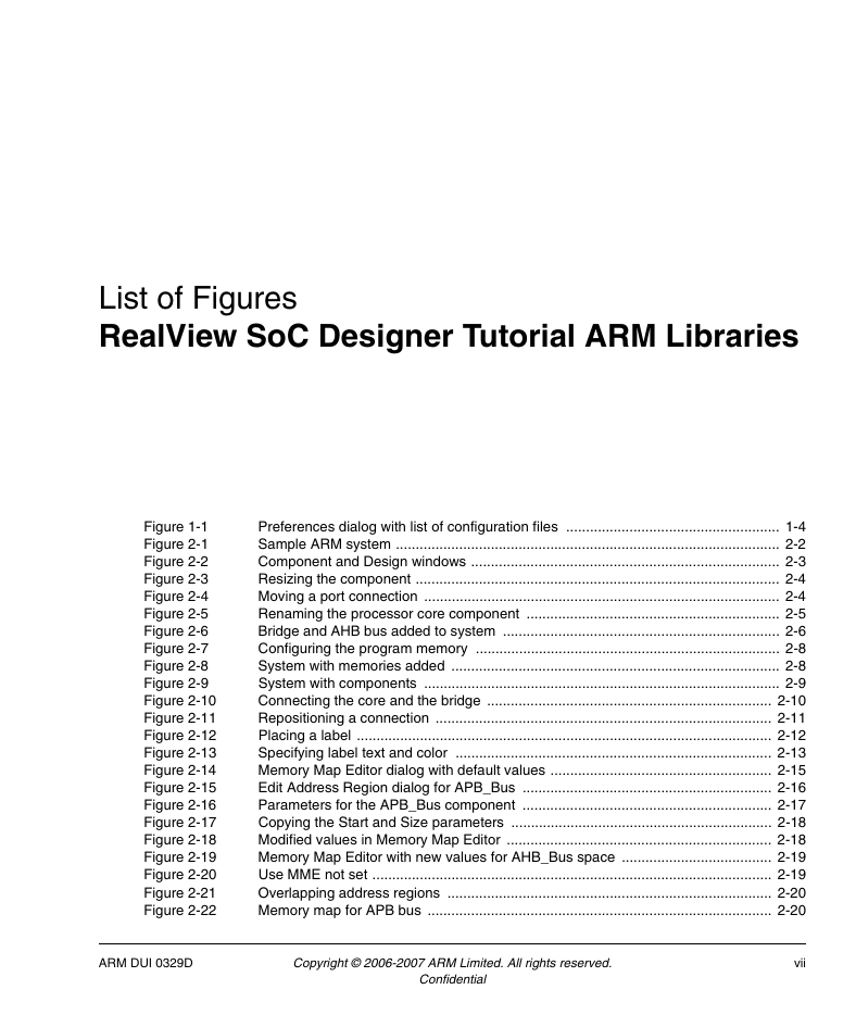
List of Figures RealView SoC Designer Tutorial ARM Libraries Figure 1-1 Figure 2-1 Figure 2-2 Figure 2-3 Figure 2-4 Figure 2-5 Figure 2-6 Figure 2-7 Figure 2-8 Figure 2-9 Figure 2-10 Figure 2-11 Figure 2-12 Figure 2-13 Figure 2-14 Figure 2-15 Figure 2-16 Figure 2-17 Figure 2-18 Figure 2-19 Figure 2-20 Figure 2-21 Figure 2-22 Preferences dialog with list of configuration files ...................................................... 1-4 Sample ARM system ................................................................................................. 2-2 Component and Design windows .............................................................................. 2-3 Resizing the component ............................................................................................ 2-4 Moving a port connection .......................................................................................... 2-4 Renaming the processor core component ................................................................ 2-5 Bridge and AHB bus added to system ...................................................................... 2-6 Configuring the program memory ............................................................................. 2-8 System with memories added ................................................................................... 2-8 System with components .......................................................................................... 2-9 Connecting the core and the bridge ........................................................................ 2-10 Repositioning a connection ..................................................................................... 2-11 Placing a label ......................................................................................................... 2-12 Specifying label text and color ................................................................................ 2-13 Memory Map Editor dialog with default values ........................................................ 2-15 Edit Address Region dialog for APB_Bus ............................................................... 2-16 Parameters for the APB_Bus component ............................................................... 2-17 Copying the Start and Size parameters .................................................................. 2-18 Modified values in Memory Map Editor ................................................................... 2-18 Memory Map Editor with new values for AHB_Bus space ...................................... 2-19 Use MME not set ..................................................................................................... 2-19 Overlapping address regions .................................................................................. 2-20 Memory map for APB bus ....................................................................................... 2-20 ARM DUI 0329D Copyright © 2006-2007 ARM Limited. All rights reserved. vii Confidential
Figure 3-1 Figure 3-2 Figure 3-3 Figure 3-4 Figure 3-5 Figure 3-6 Figure 3-7 Figure 3-8 Figure 3-9 Figure 3-10 Figure 3-11 Figure 3-12 Figure 3-13 Figure 3-14 Figure 3-15 Figure 3-16 Figure 3-17 Figure 3-18 Figure 3-19 Figure 3-20 Figure 3-21 Figure 3-22 Figure 4-1 Figure 4-2 Figure 4-3 Figure 4-4 Figure 4-5 Figure 4-6 Figure 4-7 Figure 4-8 Figure 4-9 Figure 4-10 Figure 4-11 Figure 4-12 Figure 4-13 Figure 4-14 Figure 4-15 Figure 5-1 Figure 5-2 Figure 5-3 Figure 5-4 Figure 5-5 Figure 5-6 Figure 5-7 Figure 5-8 Figure 5-9 Figure 5-10 Select the application file to load into program memory ........................................... 3-3 SoC Designer with simulation file loaded ................................................................. 3-4 Setting a breakpoint on the interrupt line .................................................................. 3-5 Console I/O window to enter the number ................................................................. 3-5 Console Window output ............................................................................................ 3-6 Register view for core ............................................................................................... 3-6 Adding a trace on the isrc signal ............................................................................... 3-7 The waveform view showing the interrupt signal ...................................................... 3-8 Disassembly view of code ........................................................................................ 3-8 Executing 1000 program steps ................................................................................. 3-9 Viewing data memory ............................................................................................. 3-10 Select type dialog ................................................................................................... 3-11 Select file name ...................................................................................................... 3-12 SoC Designer Simulator ......................................................................................... 3-13 Selecting the simulation .......................................................................................... 3-14 Selecting a new application .................................................................................... 3-15 Source coloring dialog ............................................................................................ 3-16 RVD connected to simulation ................................................................................. 3-17 No source image for RVD ....................................................................................... 3-18 Select Local File to Load dialog .............................................................................. 3-19 Disassembly for code ............................................................................................. 3-20 Breakpoint on source code ..................................................................................... 3-21 ARM926EJ-S (CA) example in SoC Designer Simulator. ......................................... 4-3 Console I/O window. ................................................................................................. 4-4 Mode changing from the USR mode to IRQ and jumping to IRQ vector location. .... 4-5 Parameters for the core component ......................................................................... 4-7 Profiling Manager dialog ........................................................................................... 4-8 AHB Bus profile with a segment size of 100 ............................................................. 4-9 Zoomed in AHB Bus profile for a segment size of 100 ........................................... 4-10 AHB Bus profile viewed on a cycle-by-cycle basis ................................................. 4-10 Core Instruction Cache profiling view ..................................................................... 4-11 Core Data Cache profiling view .............................................................................. 4-11 Placing a monitor on the bus to PMEM .................................................................. 4-12 Small version of Monitor window ............................................................................ 4-12 Monitoring the AHB bus connection to PMEM ........................................................ 4-13 Monitoring the master port in the AHBBus component ........................................... 4-13 Monitor history for the master port .......................................................................... 4-14 Component Wizard dialog ........................................................................................ 5-4 Component Attributes ............................................................................................... 5-5 Port name and type .................................................................................................. 5-6 Ports added to component ........................................................................................ 5-7 Component parameters ............................................................................................ 5-8 Component registers ................................................................................................ 5-9 Summary of component specifications ................................................................... 5-11 Generation options ................................................................................................. 5-12 Component generated ............................................................................................ 5-12 Component interaction for the interrupt controller .................................................. 5-15 viii Copyright © 2006-2007 ARM Limited. All rights reserved. ARM DUI 0329D Confidential
分享到:
收藏