logo资料库

SiI3132 PCI Express to Serial ATA Controller.pdf

第1页 / 共88页
第2页 / 共88页
第3页 / 共88页
第4页 / 共88页
第5页 / 共88页
第6页 / 共88页
第7页 / 共88页
第8页 / 共88页
资料共88页,剩余部分请下载后查看
Copyright Notice
Patents
Trademark Acknowledgment
Further Information
Overview
Features
Overall Features
PCI Express Features
Serial ATA Features
Pin Diagram
Electrical Characteristics
SATA Interface Timing Specifications
SATA Interface Transmitter Output Jitter Characteristics
PCI Express Interface Timing Specifications
PCI Express Interface Transmitter Output Jitter Characteristics
CLKI SATA Reference Clock Input Requirement
Power Supply Noise Requirements
Pin Descriptions
PCI Express Pins
Flash Data and Address Pins
FLSAH Control, I2C, and LED Pins
Serial ATA Pins
Test Pins
Power/Ground Pins
Pin List by Pin Number
Package Drawing
Marking Specification
Ordering Information
Programming Model
SiI3132 Block Diagram
SiI3132 SATA Port Block Diagram
Direct Command Transfer Method – Host controlled write to Slot
Indirect Command Transfer Method – SiI3132 controlled command transfer
Data Structures
The Command Slot
The Scatter/Gather Entry (SGE)
The Scatter/Gather Table (SGT)
The Port Request Block (PRB)
The PRB Control Field
The PRB Protocol Override Field
Standard ATA Command PRB Structure
PACKET Command PRB Structure
Soft Reset PRB Structure
External Command PRB Structure
Interlocked Receive PRB Structure
Operation
Methods to Issue Commands
Reset and Initialization
PERST# Reset
Global Reset
Port Reset
Device Reset
Port Initialize
Port Ready
Port Reset Operation
Initialization Sequence
Initialize Port and Retrieve Device Signature
Port Multiplier Enumeration Procedure
ATAPI PACKET Device Procedure
Disk Drive Procedure
Interrupts and Command Completion
Interrupt Sources
Command Completion — The Slot Status Registers
The Attention Bit
Interrupt Service Procedure
Interrupt No Clear on Read
Error Processing
Error Recovery Procedures
Auto-Initialization
Auto-Initialization from Flash
Auto-Initialization from EEPROM
Register Definitions
PCI Configuration Space
Device ID – Vendor ID
PCI Status – PCI Command
PCI Class Code – Revision ID
BIST – Header Type – Latency Timer – Cache Line Size
Base Address Register 0
Base Address Register 1
Base Address Register 2
Subsystem ID — Subsystem Vendor ID
Expansion ROM Base Address
Capabilities Pointer
Max Latency – Min Grant – Interrupt Pin – Interrupt Line
Header Write Enable
Power Management Capability
Power Management Control + Status
MSI Capability
Message Address
MSI Message Data
PCI Express Capability
Device Capabilities
Device Status and Control
Link Capabilities
Link Status and Control
Global Register Offset
Global Register Data
Port Register Offset
Port Register Data
Advanced Error Reporting Capability
Uncorrectable Error Status
Uncorrectable Error Mask
Uncorrectable Error Severity
Correctable Error Status
Correctable Error Mask
Advanced Error Capabilities and Control
Header Log
Internal Register Space – Base Address 0
Global Port Slot Status
Global Control
Global Interrupt Status
PHY Configuration
BIST Control
BIST Pattern
BIST Status
I2C Control
I2C Status
I2C Slave Address
I2C Data Buffer
Flash Address
Flash Memory Data / GPIO Control
Internal Register Space – Base Address 1
Port LRAM
Port Slot Status
Port Control Set
Port Status
Port Control Clear
Port Interrupt Status
Port Interrupt Enable Set / Port Interrupt Enable Clear
32-bit Activation Upper Address
Port Command Execution FIFO
Port Command Error
Port FIS Configuration
Port PCI Express Request FIFO Threshold
Port 8B/10B Decode Error Counter
Port CRC Error Counter
Port Handshake Error Counter
Port PHY Configuration
Port Device Status
Port Device QActive
Port Context
SControl
SStatus
SError
SActive
SNotification
Internal Register Space – Base Address 2
Global Register Offset
Global Register Data
Port Register Offset
Port Register Data
Power Management
Flash, GPIO, EEPROM, and I2C Programming
Flash Memory Access
PCI Direct Access
Register Access
Flash Write Operation
Flash Read Operation
I2C Operation
I2C Master Write Operation
I2C Master Read Operation
Setup for a Read Operation
Read the Data
I2C Slave Read Operations
Standards Documents
Disclaimers
Products and Services
Data Sheet SiI3132 PCI Express to Serial ATA Controller Data Sheet Document # SiI-DS-0138-E
SiI3132 PCI Express to Serial ATA Controller Data Sheet Silicon Image, Inc. May, 2010 Copyright Notice Copyright © 2007-2010 Silicon Image, Inc. All rights reserved. These materials contain proprietary and confidential information (including trade secrets, copyright, and other interests) of Silicon Image, Inc. You may not use these materials except only for your bona fide non-commercial evaluation of your potential purchase of products and/or services from Silicon Image or its affiliates, and/or only in connection with your purchase of products and/or services from Silicon Image or its affiliates, and only in accordance with the terms and conditions herein. You have no right to copy, modify, transfer, sublicense, publicly display, create derivative works of or distribute these materials, or otherwise make these materials available, in whole or in part, to any third party. Patents The subject matter described herein contains one or more inventions claimed in patents and/or patents pending owned by Silicon Image, Inc., including but not limited to the inventions claimed in US patents #6,914,637, #6,151,334, #6,026,124, #5,974,464 and #5,825,824. Trademark Acknowledgment Silicon Image™, VastLane™, SteelVine™, PinnaClear™, Simplay™, Simplay HD™, Satalink™, InstaPort™, and TMDS™ are trademarks or registered trademarks of Silicon Image, Inc. in the United States and other countries. HDMI®, the HDMI logo and High-Definition Multimedia Interface™ are trademarks or registered trademarks of, and are used under license from, HDMI Licensing, LLC. x.v.Color™ is a trademark of Sony Corporation. Further Information To request other materials, documentation, and information, contact your local Silicon Image, Inc. sales office or visit the Silicon Image, Inc. web site at www.siliconimage.com. Revision History Revision Date Comment A A01 A02 C D E 4/8/2005 Derived from preliminary datasheet rev 0.3 8/15/2005 Updated register description for BAR0 Offset 50H 8/11/2006 Corrected inconsistent sentences (minor fixes including mistyping) 2/2/2007 2/23/2007 Changes to package drawing. New formatting applied. 5/7/2010 Added I2C section; rewrote Initialization Sequence section; copyedited and brought to current standards. Removed confidential markings (no longer under NDA); updated Marking Specification. © 2007-2010 Silicon Image. Inc. All rights reserved. ii © 2007-2010 Silicon Image, Inc. All rights reserved SiI-DS-0138-E
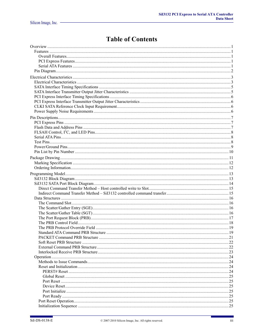
Silicon Image, Inc. SiI3132 PCI Express to Serial ATA Controller Data Sheet Table of Contents Overview ..............................................................................................................................................................................1 Features ............................................................................................................................................................................1 Overall Features............................................................................................................................................................1 PCI Express Features....................................................................................................................................................1 Serial ATA Features ......................................................................................................................................................1 Pin Diagram......................................................................................................................................................................2 Electrical Characteristics ......................................................................................................................................................3 Electrical Characteristics ..................................................................................................................................................3 SATA Interface Timing Specifications .............................................................................................................................5 SATA Interface Transmitter Output Jitter Characteristics ................................................................................................5 PCI Express Interface Timing Specifications...................................................................................................................6 PCI Express Interface Transmitter Output Jitter Characteristics ......................................................................................6 CLKI SATA Reference Clock Input Requirement............................................................................................................6 Power Supply Noise Requirements ..................................................................................................................................6 Pin Descriptions....................................................................................................................................................................7 PCI Express Pins ..............................................................................................................................................................7 Flash Data and Address Pins ............................................................................................................................................7 FLSAH Control, I2C, and LED Pins.................................................................................................................................8 Serial ATA Pins.................................................................................................................................................................8 Test Pins............................................................................................................................................................................8 Power/Ground Pins...........................................................................................................................................................9 Pin List by Pin Number ..................................................................................................................................................10 Package Drawing................................................................................................................................................................ 11 Marking Specification ....................................................................................................................................................12 Ordering Information......................................................................................................................................................12 Programming Model...........................................................................................................................................................13 SiI3132 Block Diagram..................................................................................................................................................13 SiI3132 SATA Port Block Diagram................................................................................................................................14 Direct Command Transfer Method – Host controlled write to Slot............................................................................15 Indirect Command Transfer Method – SiI3132 controlled command transfer...........................................................15 Data Structures ...............................................................................................................................................................16 The Command Slot.....................................................................................................................................................16 The Scatter/Gather Entry (SGE).................................................................................................................................16 The Scatter/Gather Table (SGT).................................................................................................................................16 The Port Request Block (PRB)...................................................................................................................................17 The PRB Control Field...............................................................................................................................................18 The PRB Protocol Override Field ..............................................................................................................................19 Standard ATA Command PRB Structure ....................................................................................................................19 PACKET Command PRB Structure ...........................................................................................................................21 Soft Reset PRB Structure ...........................................................................................................................................22 External Command PRB Structure.............................................................................................................................22 Interlocked Receive PRB Structure............................................................................................................................23 Operation........................................................................................................................................................................24 Methods to Issue Commands......................................................................................................................................24 Reset and Initialization ...............................................................................................................................................24 PERST# Reset ........................................................................................................................................................24 Global Reset ...........................................................................................................................................................25 Port Reset ...............................................................................................................................................................25 Device Reset...........................................................................................................................................................25 Port Initialize ..........................................................................................................................................................25 Port Ready ..............................................................................................................................................................25 Port Reset Operation...................................................................................................................................................25 Initialization Sequence ...............................................................................................................................................25 SiI-DS-0138-E © 2007-2010 Silicon Image, Inc. All rights reserved. iii
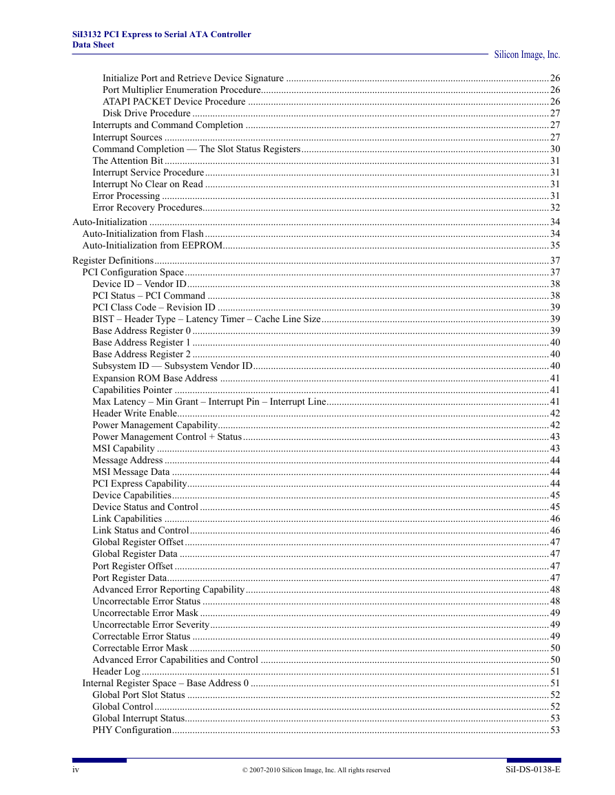
SiI3132 PCI Express to Serial ATA Controller Data Sheet Silicon Image, Inc. Initialize Port and Retrieve Device Signature ........................................................................................................26 Port Multiplier Enumeration Procedure..................................................................................................................26 ATAPI PACKET Device Procedure .......................................................................................................................26 Disk Drive Procedure .............................................................................................................................................27 Interrupts and Command Completion ........................................................................................................................27 Interrupt Sources ........................................................................................................................................................27 Command Completion — The Slot Status Registers..................................................................................................30 The Attention Bit ........................................................................................................................................................31 Interrupt Service Procedure........................................................................................................................................31 Interrupt No Clear on Read ........................................................................................................................................31 Error Processing .........................................................................................................................................................31 Error Recovery Procedures.........................................................................................................................................32 Auto-Initialization ..............................................................................................................................................................34 Auto-Initialization from Flash........................................................................................................................................34 Auto-Initialization from EEPROM.................................................................................................................................35 Register Definitions............................................................................................................................................................37 PCI Configuration Space................................................................................................................................................37 Device ID – Vendor ID...............................................................................................................................................38 PCI Status – PCI Command .......................................................................................................................................38 PCI Class Code – Revision ID ...................................................................................................................................39 BIST – Header Type – Latency Timer – Cache Line Size..........................................................................................39 Base Address Register 0 .............................................................................................................................................39 Base Address Register 1 .............................................................................................................................................40 Base Address Register 2 .............................................................................................................................................40 Subsystem ID — Subsystem Vendor ID.....................................................................................................................40 Expansion ROM Base Address ..................................................................................................................................41 Capabilities Pointer ....................................................................................................................................................41 Max Latency – Min Grant – Interrupt Pin – Interrupt Line........................................................................................41 Header Write Enable...................................................................................................................................................42 Power Management Capability...................................................................................................................................42 Power Management Control + Status.........................................................................................................................43 MSI Capability ...........................................................................................................................................................43 Message Address ........................................................................................................................................................44 MSI Message Data .....................................................................................................................................................44 PCI Express Capability...............................................................................................................................................44 Device Capabilities.....................................................................................................................................................45 Device Status and Control ..........................................................................................................................................45 Link Capabilities ........................................................................................................................................................46 Link Status and Control..............................................................................................................................................46 Global Register Offset................................................................................................................................................47 Global Register Data ..................................................................................................................................................47 Port Register Offset ....................................................................................................................................................47 Port Register Data.......................................................................................................................................................47 Advanced Error Reporting Capability........................................................................................................................48 Uncorrectable Error Status .........................................................................................................................................48 Uncorrectable Error Mask ..........................................................................................................................................49 Uncorrectable Error Severity......................................................................................................................................49 Correctable Error Status .............................................................................................................................................49 Correctable Error Mask ..............................................................................................................................................50 Advanced Error Capabilities and Control ..................................................................................................................50 Header Log.................................................................................................................................................................51 Internal Register Space – Base Address 0 ......................................................................................................................51 Global Port Slot Status ...............................................................................................................................................52 Global Control............................................................................................................................................................52 Global Interrupt Status................................................................................................................................................53 PHY Configuration.....................................................................................................................................................53 iv © 2007-2010 Silicon Image, Inc. All rights reserved SiI-DS-0138-E
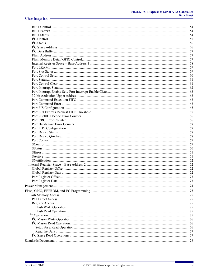
Silicon Image, Inc. SiI3132 PCI Express to Serial ATA Controller Data Sheet BIST Control ..............................................................................................................................................................54 BIST Pattern ...............................................................................................................................................................54 BIST Status.................................................................................................................................................................54 I2C Control..................................................................................................................................................................55 I2C Status....................................................................................................................................................................56 I2C Slave Address.......................................................................................................................................................56 I2C Data Buffer...........................................................................................................................................................57 Flash Address .............................................................................................................................................................57 Flash Memory Data / GPIO Control...........................................................................................................................57 Internal Register Space – Base Address 1 ..................................................................................................................58 Port LRAM.................................................................................................................................................................59 Port Slot Status ...........................................................................................................................................................59 Port Control Set ..........................................................................................................................................................60 Port Status...................................................................................................................................................................61 Port Control Clear.......................................................................................................................................................61 Port Interrupt Status....................................................................................................................................................62 Port Interrupt Enable Set / Port Interrupt Enable Clear..............................................................................................63 32-bit Activation Upper Address................................................................................................................................63 Port Command Execution FIFO.................................................................................................................................63 Port Command Error ..................................................................................................................................................63 Port FIS Configuration ...............................................................................................................................................65 Port PCI Express Request FIFO Threshold................................................................................................................65 Port 8B/10B Decode Error Counter ...........................................................................................................................66 Port CRC Error Counter .............................................................................................................................................66 Port Handshake Error Counter ...................................................................................................................................67 Port PHY Configuration .............................................................................................................................................67 Port Device Status ......................................................................................................................................................68 Port Device QActive...................................................................................................................................................68 Port Context................................................................................................................................................................69 SControl......................................................................................................................................................................69 SStatus ........................................................................................................................................................................70 SError .........................................................................................................................................................................71 SActive .......................................................................................................................................................................71 SNotification...............................................................................................................................................................72 Internal Register Space – Base Address 2 ......................................................................................................................72 Global Register Offset................................................................................................................................................72 Global Register Data ..................................................................................................................................................72 Port Register Offset ....................................................................................................................................................73 Port Register Data.......................................................................................................................................................73 Power Management............................................................................................................................................................74 Flash, GPIO, EEPROM, and I2C Programming .................................................................................................................75 Flash Memory Access.....................................................................................................................................................75 PCI Direct Access.......................................................................................................................................................75 Register Access...........................................................................................................................................................75 Flash Write Operation.............................................................................................................................................75 Flash Read Operation .............................................................................................................................................75 I2C Operation..................................................................................................................................................................75 I2C Master Write Operation........................................................................................................................................76 I2C Master Read Operation.........................................................................................................................................76 Setup for a Read Operation ....................................................................................................................................76 Read the Data .........................................................................................................................................................77 I2C Slave Read Operations .........................................................................................................................................77 Standards Documents .........................................................................................................................................................78 SiI-DS-0138-E © 2007-2010 Silicon Image, Inc. All rights reserved. v
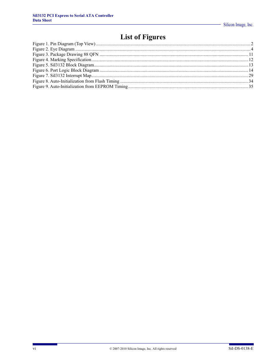
SiI3132 PCI Express to Serial ATA Controller Data Sheet Silicon Image, Inc. List of Figures Figure 1. Pin Diagram (Top View) .......................................................................................................................................2 Figure 2. Eye Diagram .........................................................................................................................................................4 Figure 3. Package Drawing 88 QFN .................................................................................................................................. 11 Figure 4. Marking Specification.........................................................................................................................................12 Figure 5. SiI3132 Block Diagram.......................................................................................................................................13 Figure 6. Port Logic Block Diagram ..................................................................................................................................14 Figure 7. SiI3132 Interrupt Map.........................................................................................................................................29 Figure 8. Auto-Initialization from Flash Timing ................................................................................................................34 Figure 9. Auto-Initialization from EEPROM Timing.........................................................................................................35 vi © 2007-2010 Silicon Image, Inc. All rights reserved SiI-DS-0138-E
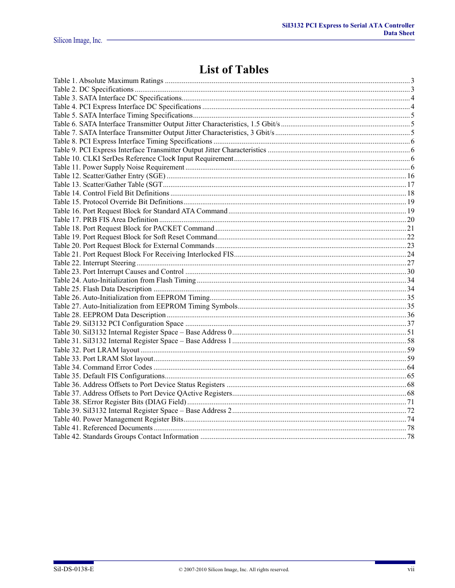
Silicon Image, Inc. SiI3132 PCI Express to Serial ATA Controller Data Sheet List of Tables Table 1. Absolute Maximum Ratings ...................................................................................................................................3 Table 2. DC Specifications ...................................................................................................................................................3 Table 3. SATA Interface DC Specifications..........................................................................................................................4 Table 4. PCI Express Interface DC Specifications ...............................................................................................................4 Table 5. SATA Interface Timing Specifications....................................................................................................................5 Table 6. SATA Interface Transmitter Output Jitter Characteristics, 1.5 Gbit/s.....................................................................5 Table 7. SATA Interface Transmitter Output Jitter Characteristics, 3 Gbit/s........................................................................5 Table 8. PCI Express Interface Timing Specifications .........................................................................................................6 Table 9. PCI Express Interface Transmitter Output Jitter Characteristics ............................................................................6 Table 10. CLKI SerDes Reference Clock Input Requirement..............................................................................................6 Table 11. Power Supply Noise Requirement ........................................................................................................................6 Table 12. Scatter/Gather Entry (SGE) ................................................................................................................................16 Table 13. Scatter/Gather Table (SGT..................................................................................................................................17 Table 14. Control Field Bit Definitions ..............................................................................................................................18 Table 15. Protocol Override Bit Definitions.......................................................................................................................19 Table 16. Port Request Block for Standard ATA Command...............................................................................................19 Table 17. PRB FIS Area Definition ....................................................................................................................................20 Table 18. Port Request Block for PACKET Command......................................................................................................21 Table 19. Port Request Block for Soft Reset Command.....................................................................................................22 Table 20. Port Request Block for External Commands ......................................................................................................23 Table 21. Port Request Block For Receiving Interlocked FIS............................................................................................24 Table 22. Interrupt Steering ................................................................................................................................................27 Table 23. Port Interrupt Causes and Control ......................................................................................................................30 Table 24. Auto-Initialization from Flash Timing................................................................................................................34 Table 25. Flash Data Description .......................................................................................................................................34 Table 26. Auto-Initialization from EEPROM Timing.........................................................................................................35 Table 27. Auto-Initialization from EEPROM Timing Symbols..........................................................................................35 Table 28. EEPROM Data Description................................................................................................................................36 Table 29. SiI3132 PCI Configuration Space ......................................................................................................................37 Table 30. SiI3132 Internal Register Space – Base Address 0.............................................................................................51 Table 31. SiI3132 Internal Register Space – Base Address 1.............................................................................................58 Table 32. Port LRAM layout ..............................................................................................................................................59 Table 33. Port LRAM Slot layout.......................................................................................................................................59 Table 34. Command Error Codes .......................................................................................................................................64 Table 35. Default FIS Configurations.................................................................................................................................65 Table 36. Address Offsets to Port Device Status Registers ................................................................................................68 Table 37. Address Offsets to Port Device QActive Registers.............................................................................................68 Table 38. SError Register Bits (DIAG Field) .....................................................................................................................71 Table 39. SiI3132 Internal Register Space – Base Address 2.............................................................................................72 Table 40. Power Management Register Bits.......................................................................................................................74 Table 41. Referenced Documents.......................................................................................................................................78 Table 42. Standards Groups Contact Information ..............................................................................................................78 SiI-DS-0138-E © 2007-2010 Silicon Image, Inc. All rights reserved. vii
SiI3132 PCI Express to Serial ATA Controller Data Sheet Silicon Image, Inc. viii © 2007-2010 Silicon Image, Inc. All rights reserved SiI-DS-0138-E
分享到:
收藏