logo资料库

ctia_mimo_ota_tp_v1_1_1.pdf

第1页 / 共84页
第2页 / 共84页
第3页 / 共84页
第4页 / 共84页
第5页 / 共84页
第6页 / 共84页
第7页 / 共84页
第8页 / 共84页
资料共84页,剩余部分请下载后查看
Section 1 Introduction
1.1 Purpose
1.2 Scope
1.3 Applicable Documents
1.4 Acronyms and Definitions
1.5 MIMO OTA Test Overview
1.6 MIMO Equipment under Test and Accessories-The Wireless Device
1.7 Wireless Device Documentation
1.8 Over-the-Air Test System
1.8.1 Multi-Probe Anechoic Chamber (MPAC)
Section 2 MIMO Receiver Performance Assessment (Open-Loop Spatial Multiplexing)
2.1 MPAC General Description
2.2 MPAC System Setup
2.2.1 MPAC Ripple Test
2.2.2 MPAC Calibration
2.2.2.1 Input Calibration
2.2.2.2 Output Calibration
2.2.2.3 Channel Emulator Input Phase Calibration
2.3 EUT Positioning within the MPAC Test Volume
2.3.1 EUT Free-Space Orientation within the MPAC Test Zone
2.3.2 MPAC EUT Orientation within the Test Zone using Phantoms
2.3.3 Maximum EUT Antenna Spacing and Placement of EUT within the Test Zone
2.3.3.1 EUT Placement, Frequency of Operation < 1GHz
2.3.3.2 EUT Placement, Frequency of Operation > 1GHz
2.4 MIMO Average Radiated SIR Sensitivity (MARSS)
2.4.1 Introduction
2.4.2 eNodeB Emulator Configuration
2.4.3 Channel Model Definition
2.4.4 Channel Model Emulation of the Base Station Antenna Pattern
2.4.5 Signal to Interference Ratio (SIR) Control for MARSS Measurement
2.4.5.1 SIR Control for the MPAC Test Environment
2.4.5.2 SIR Validation within the MPAC Test Zone
2.5 MPAC MIMO OTA Test Requirements
2.5.1 Introduction
2.5.2 Throughput Calculation
2.5.3 MIMO OTA Test Frequencies
2.6 MPAC MIMO OTA Test Methodology
2.6.1 Introduction
2.6.2 SIR-Controlled Test Procedure Using the MPAC
2.6.3 MARSS Figure of Merit
Section 3 Transmit Diversity Receiver Performance Evaluation
Section 4 Implementation Conformance Statements Applicable to MIMO and Transmit Diversity OTA Performance Measurement
Section 5 Measurement Uncertainty
5.1 Introduction
5.2 Common Uncertainty Contributions due to Mismatch
5.3 Common Uncertainty Contributions for a Receiving Device
5.4 Common Uncertainty Contributions for a Signal Source
5.5 Common Uncertainty Contributions for Measurement/Probe Antennas
5.5.1 Substitution Components
5.6 Common Uncertainty Contributions for Measurement Setup
5.6.1 Offset of the Phase Center of the Calibrated Reference Antenna from Axis(es) of Rotation
5.6.2 Influence of the Ambient Temperature on the Test Equipment
5.6.3 Miscellaneous Uncertainty
5.6.4 Minimum Downlink/Interference Power Step Size:
5.7 Typical Uncertainty Contributions for External Amplifier
5.7.1 Gain
5.7.2 Mismatch
5.7.3 Stability
5.7.4 Linearity
5.7.5 Amplifier Noise Figure/Noise Floor
5.8 Common Uncertainty Contributions for EUT
5.8.1 Measurement Setup Repeatability
5.8.2 Effect of Ripple on EUT Measurement
5.9 Typical Uncertainty Contributions for Reference Measurement
5.9.1 Effect of Ripple on Range Reference Measurements
5.10 Path Loss Measurement Uncertainty
5.10.1 Substitution Components:
5.11 Summary of Common Uncertainty Contributions for MIMO Receiver Performance
5.12 Combined and Expanded Uncertainties for Overall MIMO Receiver Performance
5.12.1 Compliance Criteria for the Overall MIMO Receiver Performance Uncertainty
5.13 Combined and Expanded Uncertainties and Compliance Criteria for the Transmit Diversity Receiver Performance
Appendix A—Validation and Verification of Test Environments and Test Conditions (Normative)
A.1 Measurement Instrument Overview
A.1.1 Measurement instruments and Setup
A.1.2 Network Analyzer (VNA) Setup
A.1.3 Spectrum Analyzer (SA) Setup
A.2 Validation of the MPAC MIMO OTA Test Environment and Test Conditions
A.2.1 Validation of SIR-Controlled MPAC Test Environment
A.2.1.1 Validation of MPAC Power Delay Profile (PDP)
A.2.1.2 Power Delay Profile Result Analysis
A.2.1.3 Measurement Antenna
A.2.1.4 Pass/Fail Criteria
A.2.2 Validation of Doppler/Temporal Correlation for MPAC
A.2.2.1 MPAC Doppler/Temporal Correlation Method of Measurement
A.2.2.2 MPAC Doppler/Temporal Correlation Measurement Antenna
A.2.3 Validation of MPAC Spatial Correlation
A.2.3.1 MPAC Spatial Correlation Method of Measurement
A.2.3.2 MPAC Spatial Correlation Measurement Results Analysis
A.2.3.3 MPAC Spatial Correlation Measurement Antenna
A.2.4 Validation of Cross-Polarization for MPAC
A.2.4.1 MPAC Cross Polarization Method of Measurement
A.2.4.2 MPAC Cross Polarization Measurement Procedure
A.2.4.3 MPAC Cross Polarization Expected Measurement Results
A.2.5 Input Phase Calibration Validation (Normative)
Appendix B — Validation of Transmit Diversity Receiver Performance Test Environments and Test Conditions
Appendix C — Reporting Test Results (Normative)
C.1 MARSS Radiated Measurement Data Format
C.2 Transmit Diversity Radiated Measurement Data Format
Appendix D— EUT Orientation Conditions (Normative)
D.1 Scope
D.2 Testing Environment Conditions
Appendix E — EUT Orientation Conditions (Informative)
E.1 Scope
E.2 Testing Environment Conditions
Appendix F — Test Zone Dimension Definitions for Optional Bands
Appendix G—Change History
Test Plan for 2x2 Downlink MIMO and Transmit Diversity Over-the-Air Performance Version 1.1.1 September 2017 © 2016 CTIA - The Wireless Association®. All rights reserved. CTIA hereby grants to CTIA Authorized Testing Laboratories (CATLs), and only to CATLs, a limited, non- transferable license to use this Test Plan for the sole purpose of testing wireless devices for the CTIA Certification Program, and to reproduce this Test Plan for internal use only. Any other use of this Test Plan must be authorized in writing by CTIA. Any reproduction or transmission of all or part of this Test Plan, in any form or by any means, electronic or mechanical, including photocopying, recording, or via any information storage and retrieval system, without the prior written permission of CTIA, is unauthorized and strictly prohibited. Any reproduction of this Test Plan shall display the notice: "Copyright by CTIA. All rights reserved."
Certification Program Test Plan CTIA Certification Program 1400 16th Street, NW Suite 600 Washington, DC 20036 certification@ctia.org 1.202.785.0081 www.ctia.org/certification September 2017 2 Version 1.1.1
Acknowledgements Certification Program Test Plan This test plan was created by the wireless industry with input from the following companies and their representatives: Company, Representative Company, Representative Anite Telecoms: Aki Hekkala, Lassi Hentila, Karthikesh Raju Qualcomm: Greg Breit, Vince Butsumyo, Ernie Ozaki, Ali Tassoudji, Allen Tran Apple: Alejandro Marquez Microsoft: Kevin Li AT&T: Darwin Parra, Ryan Pirkl, Scott Prather MVG: Kim Rutkowski, Alessandro Scannavini Azimuth Systems: Eric Ely, John Griesing, Thorkild Hansen, Charles Wright PCTEST Engineering Lab: Ron Borsato Bluetest: Susanne Schilliger Kildal, John Kvarnstrand, Christian Patané Lötbäck, Charlie Orlenius, Derek Skousen CTTL: Xudong An, Justin Liu, Can Sun, Shawn Wu ETS-Lindgren: Faris Alhorr, Garth D’Abreu, Michael Foegelle, Jun Luo, Edwin Mendivil General Test Systems: Kefeng Liu Rohde & Schwarz: Christoph Gagern, Thorsten Hertel, Adam Tankielun SGS: Peter Liao Sony Mobile: Thomas Bolin, Beny Dong, Jun Wang Spirent Communications: Ron Borsato, Doug Reed, Alfonso Rodriguez-Herrera Intel: Jagjit Singh Ahsta,Xavier Carreño, Anatoliy Ioffe, Mikael Bergholz Knudsen, Günter Krenz, Tommy Nielsen, Hassan Yaghoobi, Boyan Yanakiev Sprint: Chris Hiesberger, Drew Liszewski Sporton: Elvis Yen, Lorien Chang Keysight Technologies: Satish Dhanasekaran, Steve Duffy, Ya Jing, Hongwei Kong, Moray Rumney, Xu Zhao TMC: Justin Liu, Can Sun Motorola Mobility: Tyler Brown, Eric Krenz, Paul Moller, Istvan Szini Nokia: Randy Leenerts, Kevin Li, Pertti Mäkikyrö, Mia Nurkkala T-Mobile USA: Adeel Ahmad Verizon Wireless: Andrew Youtz September 2017 3 Version 1.1.1
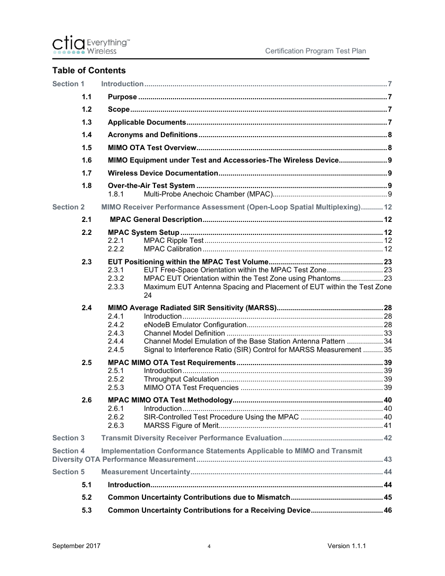
Certification Program Test Plan Table of Contents Section 1 1.1 1.2 1.3 1.4 1.5 1.6 1.7 1.8 Section 2 2.1 2.2 2.3 2.4 2.5 2.6 Introduction ......................................................................................................................... 7 Purpose ............................................................................................................................ 7 Scope ................................................................................................................................ 7 Applicable Documents .................................................................................................... 7 Acronyms and Definitions .............................................................................................. 8 MIMO OTA Test Overview ............................................................................................... 8 MIMO Equipment under Test and Accessories-The Wireless Device ........................ 9 Wireless Device Documentation .................................................................................... 9 Over-the-Air Test System ............................................................................................... 9 1.8.1 Multi-Probe Anechoic Chamber (MPAC) ......................................................... 9 MIMO Receiver Performance Assessment (Open-Loop Spatial Multiplexing) ........... 12 MPAC General Description .......................................................................................... 12 MPAC System Setup ..................................................................................................... 12 2.2.1 MPAC Ripple Test ......................................................................................... 12 2.2.2 MPAC Calibration .......................................................................................... 12 EUT Positioning within the MPAC Test Volume ......................................................... 23 EUT Free-Space Orientation within the MPAC Test Zone ............................ 23 2.3.1 2.3.2 MPAC EUT Orientation within the Test Zone using Phantoms ..................... 23 2.3.3 Maximum EUT Antenna Spacing and Placement of EUT within the Test Zone 24 MIMO Average Radiated SIR Sensitivity (MARSS) ..................................................... 28 2.4.1 Introduction .................................................................................................... 28 eNodeB Emulator Configuration .................................................................... 28 2.4.2 Channel Model Definition .............................................................................. 33 2.4.3 2.4.4 Channel Model Emulation of the Base Station Antenna Pattern .................. 34 2.4.5 Signal to Interference Ratio (SIR) Control for MARSS Measurement .......... 35 MPAC MIMO OTA Test Requirements ......................................................................... 39 Introduction .................................................................................................... 39 2.5.1 2.5.2 Throughput Calculation ................................................................................. 39 2.5.3 MIMO OTA Test Frequencies ....................................................................... 39 MPAC MIMO OTA Test Methodology........................................................................... 40 Introduction .................................................................................................... 40 2.6.1 SIR-Controlled Test Procedure Using the MPAC ......................................... 40 2.6.2 2.6.3 MARSS Figure of Merit.................................................................................. 41 Transmit Diversity Receiver Performance Evaluation .................................................. 42 Implementation Conformance Statements Applicable to MIMO and Transmit Section 3 Section 4 Diversity OTA Performance Measurement ............................................................................................. 43 Measurement Uncertainty ................................................................................................ 44 Section 5 Introduction .................................................................................................................... 44 Common Uncertainty Contributions due to Mismatch .............................................. 45 Common Uncertainty Contributions for a Receiving Device .................................... 46 5.1 5.2 5.3 September 2017 4 Version 1.1.1
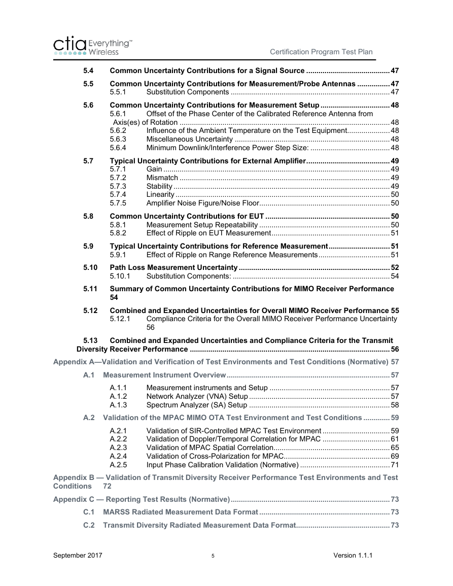
Certification Program Test Plan 5.4 5.5 5.6 5.7 5.8 5.9 5.10 5.11 Offset of the Phase Center of the Calibrated Reference Antenna from Common Uncertainty Contributions for a Signal Source ......................................... 47 Common Uncertainty Contributions for Measurement/Probe Antennas ................ 47 5.5.1 Substitution Components .............................................................................. 47 Common Uncertainty Contributions for Measurement Setup .................................. 48 5.6.1 Axis(es) of Rotation ....................................................................................................... 48 5.6.2 Influence of the Ambient Temperature on the Test Equipment..................... 48 Miscellaneous Uncertainty ............................................................................ 48 5.6.3 5.6.4 Minimum Downlink/Interference Power Step Size: ....................................... 48 Typical Uncertainty Contributions for External Amplifier ......................................... 49 5.7.1 Gain ............................................................................................................... 49 Mismatch ....................................................................................................... 49 5.7.2 Stability .......................................................................................................... 49 5.7.3 Linearity ......................................................................................................... 50 5.7.4 5.7.5 Amplifier Noise Figure/Noise Floor ................................................................ 50 Common Uncertainty Contributions for EUT ............................................................. 50 Measurement Setup Repeatability ................................................................ 50 5.8.1 5.8.2 Effect of Ripple on EUT Measurement .......................................................... 51 Typical Uncertainty Contributions for Reference Measurement .............................. 51 5.9.1 Effect of Ripple on Range Reference Measurements ................................... 51 Path Loss Measurement Uncertainty .......................................................................... 52 5.10.1 Substitution Components: ............................................................................. 54 Summary of Common Uncertainty Contributions for MIMO Receiver Performance 54 5.12 Combined and Expanded Uncertainties for Overall MIMO Receiver Performance 55 Compliance Criteria for the Overall MIMO Receiver Performance Uncertainty 56 5.12.1 5.13 Combined and Expanded Uncertainties and Compliance Criteria for the Transmit A.1.1 A.1.2 A.1.3 Diversity Receiver Performance .................................................................................................. 56 Appendix A—Validation and Verification of Test Environments and Test Conditions (Normative) 57 A.1 Measurement Instrument Overview ................................................................................ 57 Measurement instruments and Setup ........................................................... 57 Network Analyzer (VNA) Setup ..................................................................... 57 Spectrum Analyzer (SA) Setup ..................................................................... 58 A.2 Validation of the MPAC MIMO OTA Test Environment and Test Conditions ............. 59 Validation of SIR-Controlled MPAC Test Environment ................................. 59 Validation of Doppler/Temporal Correlation for MPAC ................................. 61 Validation of MPAC Spatial Correlation ......................................................... 65 Validation of Cross-Polarization for MPAC.................................................... 69 Input Phase Calibration Validation (Normative) ............................................ 71 Appendix B — Validation of Transmit Diversity Receiver Performance Test Environments and Test Conditions Appendix C — Reporting Test Results (Normative) .............................................................................. 73 C.1 MARSS Radiated Measurement Data Format ................................................................ 73 C.2 Transmit Diversity Radiated Measurement Data Format .............................................. 73 A.2.1 A.2.2 A.2.3 A.2.4 A.2.5 72 September 2017 5 Version 1.1.1
Certification Program Test Plan Appendix D— EUT Orientation Conditions (Normative) ....................................................................... 74 D.1 Scope ................................................................................................................................. 74 D.2 Testing Environment Conditions .................................................................................... 74 Appendix E — EUT Orientation Conditions (Informative) .................................................................... 77 E.1 Scope ................................................................................................................................. 77 E.2 Testing Environment Conditions .................................................................................... 77 Appendix F — Test Zone Dimension Definitions for Optional Bands ................................................. 82 Appendix G—Change History .................................................................................................................. 84 September 2017 6 Version 1.1.1
Section 1 Introduction 1.1 Purpose Certification Program Test Plan The purpose of this document is to define the CTIA Certification program test methodology for radiated performance measurements of LTE 2x2 downlink MIMO wireless devices. Future revisions of this test plan may also include methodologies for assessing radiated performance during non- MIMO operation using transmit diversity. 1.2 Scope This test plan defines general requirements for test systems, test conditions, equipment configurations, laboratory techniques, test methodologies, and evaluation criteria that must be met in order to ensure the accurate, repeatable, and uniform testing of wireless devices capable of supporting LTE 2x2 downlink MIMO. Future revisions of this document may include the equipment configurations, test methodologies, and evaluation criteria required to assess the EUT’s transmit diversity performance. This test plan provides high level test procedures and basic test equipment configuration information but does not include detailed test instructions by which to execute certification testing. Such documentation and procedures must be presented by the CTIA Authorized Test Lab (CATL) as part of the CTIA authorization process and subsequently employed and maintained by the CATL to remain authorized to perform Certification testing. 1.3 Applicable Documents [1] 3GPP TR 37.977: Verification of radiated multi-antenna reception performance of User Equipment (UE) [2] 3GPP TS 36.213: Physical layer procedures [3] 3GPP TS 36.508: Common test environments for User Equipment (UE) conformance testing [4] 3GPP TS 36.521-1: User Equipment (UE) conformance specification; Radio transmission and reception; Part 1: Conformance Testing [5] B. Yanakiev, J. Nielsen, M. Christensen, G. Pedersen: "Antennas in Real Environments", EuCAP 2011 [6] Baum, D.S.; Hansen, J.; Salo, J., "An interim channel model for beyond-3G systems: extending the 3GPP spatial channel model (SCM)," Vehicular Technology Conference, 2005. VTC 2005-Spring. 2005 IEEE 61st , vol.5, pp.3132-3136 [7] CTIA Test Plan for Wireless Device Over-the-Air Performance; Method of Measurement for Radiated RF Power and Receiver Performance [8] Guide to the expression of uncertainty in measurement, Genèva, Switzerland, International Organization for Standardization, 1995. [9] IEEE.149-1979.R2008: "IEEE Standard Test Procedures for Antennas," IEEE, December 2008 September 2017 7 Version 1.1.1
Certification Program Test Plan [10] TR 102 273: Electromagnetic compatibility and Radio spectrum Matters (ERM); Improvement on Radiated Methods of Measurement (using test site) and evaluation of the corresponding measurement uncertainties; Part 1: Uncertainties in the measurement of mobile radio equipment characteristics; Sub-part 2: Examples and annexes 1.4 Acronyms and Definitions following specialized terms and acronyms are used throughout this document. The Acronym/Term Definition DML DMP EUT Data Mode-Landscape Data Mode-Portrait Equipment Under Test Measurement Points The individual data points collected during execution of the requisite test methodology. MPAC Multi-Probe Anechoic Chamber utilized for the assessment of MIMO - capable devices. PDSCH-EPRE Packet Downlink Shared Channel-Energy Per Resource Element RS-EPRE Reference Signal-Energy Per Resource Element Test Condition Test System The emulated propagation conditions utilized within the test system. In this version of this test specification, the SCME UMa channel model is the only valid test condition. The test condition is only seen in the validated test volume of the test system. The controlled propagation environment used for evaluation of the Equipment Under Test (EUT). In the context of this version of this test specification, the Multi Probe Anechoic Chamber (MPAC) is the only valid test system. Test Methodology The process used to execute tests against the EUT using the Test System(s) and Test Condition(s) specified by this document. Test Volume The useable volume within the test system in which the EUT can be placed. The test volume is assumed to have a uniform power distribution within the uncertainty specified by the site validation. Test Zone The portion of the MPAC test volume in which the test condition criteria are met within the applicable uncertainty limits. 1.5 MIMO OTA Test Overview Downlink 2x2 MIMO allows LTE wireless devices with MIMO spatial multiplexing receiver implementations to support data rates almost twice as high as the data rates available from a 2x1 MISO downlink. This higher data rate is possible through the use of spatial multiplexing, where the September 2017 8 Version 1.1.1
分享到:
收藏