User’s Manual
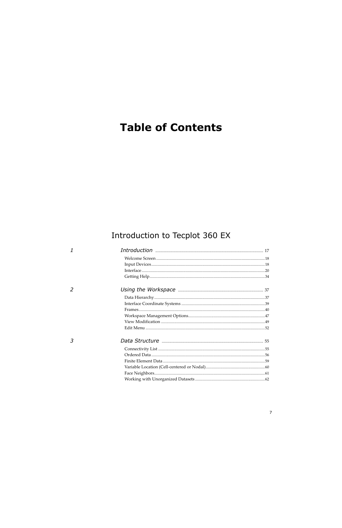
Table of Contents
Part 1 Introduction to Tecplot 360 EX
1: Introduction
1 - 1 Welcome Screen
1 - 2 Input Devices
1 - 3 Interface
1 - 3.1 Menu Bar
1 - 3.2 Context Menu and Toolbar
1 - 3.3 Sidebars
1 - 3.4 Toolbar
1 - 3.5 Status Line
1 - 3.6 Tecplot 360 EX Workspace
1 - 4 Getting Help
2: Using the Workspace
2 - 1 Data Hierarchy
2 - 1.1 Data Displays in Frames
2 - 1.2 A Dataset Includes All Data in a Frame
2 - 1.3 Datasets Are Made of Zones
2 - 2 Interface Coordinate Systems
2 - 3 Frames
2 - 3.1 The Active Frame
2 - 3.2 Frame Creation
2 - 3.3 Edit Active Frame
2 - 3.4 Frame Linking
2 - 3.5 Frame Deletion
2 - 3.6 Managing Frame Order
2 - 3.7 Save Frame Style
2 - 3.8 Load Frame Style
2 - 4 Workspace Management Options
2 - 4.1 Paper Setup
2 - 4.2 Grid and Ruler Set-Up
2 - 5 View Modification
2 - 5.1 Show a Sidebar or Toolbar
2 - 5.2 Redraw Frame
2 - 5.3 Zoom
2 - 5.4 Fit Everything
2 - 5.5 Fit Surfaces
2 - 5.6 Fit to Full Size
2 - 5.7 Data Fit
2 - 5.8 Fit All Frames to Workspace
2 - 5.9 Nice Fit to Full Size
2 - 5.10 Make Current View Nice
2 - 5.11 Center
2 - 5.12 Translate/Magnify
2 - 5.13 Last
2 - 5.14 Rotate
2 - 5.15 3D View Details
2 - 5.16 Copy View
2 - 5.17 Paste View
2 - 5.18 Fit All Frames to Workspace
2 - 6 Edit Menu
2 - 6.1 Undo
2 - 6.2 Cut
2 - 6.3 Copy
2 - 6.4 Paste
2 - 6.5 Delete
2 - 6.6 Send to Back
2 - 6.7 Bring to Front
3: Data Structure
Connectivity List
Ordered Data
Indexing Nodal Ordered Data
Indexing Cell-centered Ordered Data
One-dimensional Ordered Data (I, J, or K)
Logical versus Physical Representation of Data
Finite Element Data
Finite Element Data Limitations
Variable Location (Cell-centered or Nodal)
Face Neighbors
Working with Unorganized Datasets
Example - Unorganized Three-Dimensional Volume
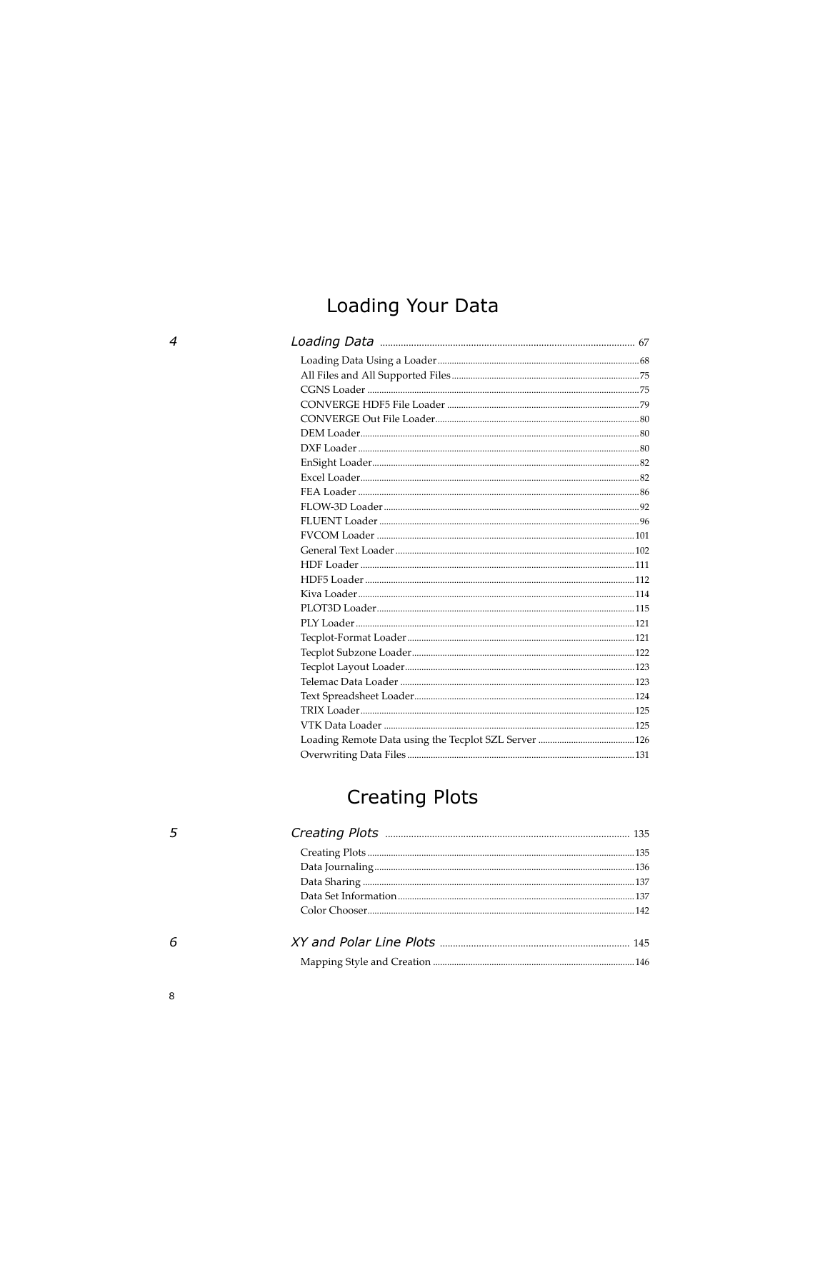
Part 2 Loading Your Data
4: Loading Data
4 - 1 Loading Data Using a Loader
4 - 2 All Files and All Supported Files
4 - 3 CGNS Loader
4 - 3.1 CGNS Support Notes
4- 3.2 Load CGNS Options: Zones Dialog
4- 3.3 Load CGNS Options: Variables dialog
4- 3.4 Macro Commands for the CGNS loader
4 - 4 CONVERGE HDF5 File Loader
4 - 4.1 Macro Commands for the CONVERGE HDF5 loader
4 - 5 CONVERGE Out File Loader
4 - 6 DEM Loader
4 - 7 DXF Loader
4 - 7.1 Load DXF File Dialog
4 - 7.2 DXF Loader Limitations
4 - 8 EnSight Loader
4- 8.1 Macro Commands for the EnSight Loader
4 - 9 Excel Loader
4 - 9.1 Spreadsheet Data Formats
4 - 9.2 Excel Loader Restrictions
4 - 10 FEA Loader
4 - 10.1 Format-Specific Notes
4 - 10.2 Loading FEA Data
4 - 10.3 Selecting Zones and Variables to Load
4 - 10.4 Appending Finite Element Data to an Existing Dataset
4 - 10.5 Post-processing Finite Element Data
4 - 10.6 Macro Commands for the FEA loader
4 - 11 FLOW-3D Loader
4 - 11.1 FLOW-3D Loader Options
4 - 11.2 FLOW-3D Macro Commands
4 - 11.3 FLOW-3D Auxiliary Data
4 - 12 FLUENT Loader
4- 12.1 Macro Commands for the FLUENT loader
4 - 13 FVCOM Loader
4 - 14 General Text Loader
4 - 14.1 Dataset Title
4 - 14.2 Variable Import Instructions
4 - 14.3 General Text Loader: Data
4 - 14.4 General Text Loader: Filters
4 - 14.5 General Text Loader: View Options
4 - 14.6 General Text Loader Configuration File
4 - 15 HDF Loader
4 - 15.1 HDF Loader Limitations
4 - 16 HDF5 Loader
4 - 16.1 Data Selection
4 - 16.2 Importing/Loading Data
4 - 16.3 Additional Options
4 - 17 Kiva Loader
4 - 17.1 Select Variable to Load
4 - 18 PLOT3D Loader
4- 18.1 File Combinations
4- 18.2 PLOT3D Loader Limitations
4- 18.3 PLOT3D File Structure
4- 18.4 PLOT3D Data Subsets
4- 18.5 Macro Language Commands for the Plot3D Loader
4- 18.6 PLOT3D Auxiliary Data
4 - 19 PLY Loader
4 - 20 Tecplot-Format Loader
4 - 20.1 Tecplot Data File Loading
4 - 21 Tecplot Subzone Loader
4 - 22 Tecplot Layout Loader
4 - 23 Telemac Data Loader
4 - 23.1 Macro Commands for the Telemac Data Loader
4 - 24 Text Spreadsheet Loader
4 - 25 TRIX Loader
4 - 26 VTK Data Loader
4- 26.1 Macro Language Commands for the VTK Data Loader
4 - 27 Loading Remote Data using the Tecplot SZL Server
4 - 27.1 Manual Connection Mode
4 - 27.2 Interactive Authentication and Unattended Operation
4 - 28 Overwriting Data Files
Part 3 Creating Plots
5: Creating Plots
5 - 1 Creating Plots
5 - 2 Data Journaling
5 - 3 Data Sharing
5 - 4 Data Set Information
5 - 4.1 Zone/Variable Info Page
5 - 4.2 Data Set Page
5 - 4.3 Aux Data Page
5 - 5 Color Chooser
5 - 5.1 RGB Coloring
5 - 5.2 Basic Color Palette
6: XY and Polar Line Plots
6 - 1 Mapping Style and Creation
6 - 1.1 Mapping Definitions
6 - 1.2 Mapping Creation
6 - 1.3 Mapping Names
6 - 2 Line Map Layer
6 - 2.1 Line Attributes
6 - 2.2 Curve Types
6 - 3 Symbols Map Layer
6 - 3.1 Symbol Attributes
6 - 3.2 Enter ASCII Character
6 - 4 XY Line Error Bars
6 - 4.1 Select Variable
6 - 4.2 Error Bar Attributes
6 - 5 XY Line Bar Charts
6 - 5.1 Bar Chart Attributes
6 - 6 I, J, and K-indices
6 - 7 Line Legend
6 - 7.1 Specify Number Format
7: Field Plots
7 - 1 Field Plot Modification and the Zone Style Dialog
7 - 1.1 Points
7 - 1.2 Surfaces
7 - 1.3 Derived Volume Object Plotting
7 - 2 Time Aware
7 - 3 Data Point and Cell Labels
7 - 4 Three-dimensional Plot Control
7 - 4.1 Reset 3D Axes
7 - 4.2 Three-dimensional Axis Limits
7 - 4.3 Three-dimensional Orientation Axis
7 - 4.4 Advanced 3D Control
7 - 4.5 The Rotate Dialog
7 - 4.6 Three-dimensional View Details
7 - 4.7 Three-Dimensional Zooming and Translating
8: Mesh Layer and Edge Layer
8 - 1 Mesh Layer
8 - 1.1 Mesh Layer Modification
8 - 1.2 Mesh Types
8 - 2 Edge Layer
8 - 2.1 Edge Layer Modification
8 - 2.2 Edge Type
8 - 2.3 Edge Display
9: Contour Layer
9 - 1 Contour Layer Modification
9 - 2 Contour & Multi-Coloring Details
9 - 2.1 Contour Groups
9 - 2.2 Contour Levels and Color
9 - 2.3 Contour Bands
9 - 2.4 Contour Lines
9 - 2.5 Contour Labels
9 - 2.6 Contour Legend
9 - 3 Extract Contour Lines
10: Vector Layer
10 - 1 Vector Variables
10 - 2 Vector Plot Modification
10 - 3 Vector Details
10 - 3.1 Length Page
10 - 3.2 Arrowhead Page
10 - 3.3 Reference Vector Page
11: Scatter Layer
11 - 1 Scatter Plot Modification
11 - 2 Scatter Size/Font
11 - 3 Scatter Legends
12: Shade Layer
12 - 1 Shade Layer Modification
13: Translucency and Lighting
13 - 1 Translucency
13 - 2 Blanking
13 - 3 Lighting Effects
13 - 4 Three-dimensional Light Source
13 - 4.1 Moving the Light Source
14: Slices
14 - 1 Interactively Created Slices
14 - 1.1 Slice Groups
14 - 1.2 Definition Page
14 - 1.3 Contour Page
14 - 1.4 Vector Page
14 - 1.5 Other Page
14 - 1.6 Animate Page
14 - 2 Extracting Slices to Zones
15: Streamtraces
15 - 1 Streamtrace Details dialog
15 - 1.1 Placement Page
15 - 1.2 Lines Page
15 - 1.3 Rod/Ribbon Page
15 - 1.4 Timing Page
15 - 1.5 Animate Page
15 - 1.6 Term Line Page
15 - 1.7 Integration Page
15 - 2 Surface Streamtraces on No-slip Boundaries
15 - 3 Streamtrace Extraction as Zones
15 - 4 Streamtrace Errors
16: Iso-surfaces
16 - 1 Iso-Surface Groups
16 - 2 Iso-Surface Definition
16 - 3 Iso-Surface Contour and Shade
16 - 4 Iso-Surface Mesh and Vector
16 - 5 Iso-Surface Animation
16 - 6 Iso-Surface Extraction
17: Axes
17 - 1 Axis Display
17 - 2 Axis Variable Assignment
17 - 3 Axis Range Options for XY and 2D/3D Plots
17 - 4 Axis Range Options for Polar Plots
17 - 5 Axis Grid Options
17 - 6 Tick Mark Options
17 - 7 Tick Mark Label Options
17 - 8 Axis Title Options
17 - 9 Axis Line Options
17 - 10 Grid Area Options
17 - 11 Time/Date Format Options
17 - 11.1 Microsoft Excel Support
17 - 11.2 Loading Time/Date Data
18: Text, Geometries, and Images
18 - 1 Text
18 - 1.1 Text Details
18 - 1.2 Font Folders and Fallback
18 - 1.3 Text Box
18 - 1.4 Special Characters
18 - 1.5 Dynamic Text
18 - 1.6 LaTeX Expressions
18 - 2 Geometries
18 - 2.1 Geometry Creation
18 - 2.2 Geometry Details
18 - 2.3 Three-dimensional Line Geometries
18 - 3 Linking Text and Geometries to Macros
Part 4 Data Manipulation
19: Blanking
19 - 1 Value Blanking
19 - 2 Value Blanking for Field Plots
19 - 3 Value Blanking Settings for Individual Zones
19 - 4 Value Blanking for Line Plots
19 - 5 IJK Blanking
19 - 6 Blanking Settings for Derived Objects
20: Data Operations
20 - 1 Data Alteration through Equations
20 - 1.1 Equation Syntax
20 - 1.2 Integration
20 - 1.3 Auxiliary Data
20 - 1.4 Zone Number Specification
20 - 1.5 Index Specification
20 - 1.6 Variable Sharing Between Zones
20 - 1.7 Equation Restriction
20 - 1.8 Macros and Equations
20 - 1.9 Equation Examples
20 - 2 Data Smoothing
20 - 2.1 Limitations of Smoothing
20 - 3 Fourier Transform
20 - 4 Axial Rotation
20 - 5 Zone Creation
20 - 5.1 Rectangular Zone Creation
20 - 5.2 Circular or Cylindrical Zone Creation
20 - 5.3 Zone Duplication
20 - 5.4 Mirror Zone Creation
20 - 5.5 Axial Duplication
20 - 6 Data Extraction from an Existing Zone
20 - 6.1 Subzone Extraction
20 - 6.2 Data Point Extraction
20 - 7 Zone Deletion
20 - 8 Variable Deletion
20 - 9 Data Interpolation
20 - 9.1 Linear Interpolation
20 - 9.2 Inverse-Distance Interpolation
20 - 9.3 Kriging
20 - 10 Irregular Data Point Triangulation
20 - 11 Data Spreadsheet
21: CFD Data Analysis
21 - 1 Specifying Fluid Properties
21 - 1.1 Specifying Incompressible Fluid Properties
21 - 1.2 Specifying Compressible Fluid Properties
21 - 1.3 Working with Non-dimensional Data
21 - 2 Specifying Reference Values
21 - 3 Identifying Field Variables
21 - 3.1 Choosing the Convective Variables
21 - 3.2 Identifying State Variables
21 - 4 Setting Geometry and Boundary Options
21 - 4.1 Performance Considerations
21 - 4.2 Specifying Boundaries and Boundary Conditions
21 - 4.3 The Edit Boundary dialog
21 - 5 Unsteady Flow
21 - 5.1 Specifying a Steady-state Solution
21 - 5.2 Group Zones by Time Step Dialog
21 - 5.3 Parsing Zone Names for Solution Time
21 - 6 Calculating Variables
21 - 6.1 Shared Variables
21 - 6.2 Calculate-on-demand Variables
21 - 6.3 Undoing a Calculation
21 - 6.4 Selecting a Function
21 - 6.5 Gradient Calculations
21 - 6.6 Surface Normal Calculations
21 - 7 Performing Integrations
21 - 7.1 Specifying Display Options
21 - 7.2 Accessing Integration Results in Macros
21 - 7.3 Integration Examples
21 - 8 Calculating Turbulence Functions
21 - 8.1 Identifying Turbulence Variables
21 - 8.2 Selecting the Variable Location
21 - 8.3 Calculating on Demand
21 - 8.4 Performing the Calculation
21 - 8.5 Shared Variables
21 - 9 Calculating Particle Paths and Streaklines
21 - 9.1 Calculating Particle Paths
21 - 9.2 Calculating Streaklines
21 - 9.3 Particles with Mass
21 - 10 Analyzing Solution Error
21 - 10.1 Calculating Solution Accuracy
21 - 10.2 Selecting Solution Zones
21 - 10.3 Specifying the Solver's Maximum Accuracy
21 - 10.4 Selecting the Dataset Variable
21 - 10.5 Plotting the Solution Accuracy
21 - 10.6 Performing the Calculation
21 - 10.7 Extrapolating a Solution
21 - 11 Extracting Fluid Flow Features
21 - 11.1 Extracting Shock Surfaces
21 - 11.2 Extracting Vortex Cores
21 - 11.3 Extracting Separation and Attachment Lines
21 - 11.4 Excluding Blanked Regions
22: Probing
22 - 1 Field Plot Probing with the Mouse
22 - 2 Field Plot Probing by Specifying Coordinates and Indices
22 - 2.1 Probe At Position
22 - 2.2 Probe at Index
22 - 3 Probe Sidebar
22 - 3.1 Variable Values
22 - 3.2 Cell Center Values
22 - 3.3 Zone and Cell Information
22 - 3.4 Face Neighbor
22 - 4 Line Plot Probing with the Mouse
22 - 4.1 Line Plot Probing in Interpolate Mode
22 - 4.2 Line Plot Probing in Nearest Point Mode
22 - 5 Data Editing
Part 5 Final Output
23: Output
23 - 1 Layout Files, Layout Package Files, Stylesheets
23 - 1.1 Creating Layouts and Stylesheets for Tecplot Focus
23 - 1.2 Working with Layout Files from Previous Releases
23 - 1.3 Exporting Backward Compatible Data Files
23 - 1.4 Stylesheets
23 - 1.5 Layout Files
23 - 1.6 Layout Package Files
23 - 1.7 Working with Layout and Layout Package Files
23 - 2 Data File Writing
24: Printing
24 - 1 Plot Printing
24 - 2 Setup
24 - 2.1 Printing Setup for Windows
24 - 2.2 Printing Setup for Linux
25: Exporting
25 - 1 Layout Packages
25 - 2 Vector Graphics Format
25 - 2.1 EPS Export
25 - 2.2 PostScript (PS) Export
25 - 2.3 WMF Export
25 - 3 Image Format
25 - 3.1 Exporting Images with a Specific DPI
25 - 3.2 BMP Export
25 - 3.3 JPEG Export
25 - 3.4 PNG Export
25 - 3.5 TIFF Export
25 - 4 Antialiasing Images
25 - 5 Clipboard Exporting to Other Applications
Part 6 Scripting
26: Macros
26 - 1 Macro Creation
26 - 1.1 Macro Functions
26 - 1.2 Macro Linking to Geometries
26 - 2 Macro Playback
26 - 2.1 Quick Macro Panel
26 - 3 Macro Debugger
26 - 3.1 Watching Variables
26 - 3.2 Using Breakpoints
27: Batch Processing
27 - 1 Batch Processing Setup
27 - 1.1 Batch Mode and Windows
27 - 1.2 Batch Mode and Mac
27 - 2 Batch Processing Using a Layout File
27 - 3 Multiple Data File Processing
27 - 3.1 Looping Outside Tecplot 360 EX
27 - 3.2 Looping Inside Tecplot 360 EX
27 - 4 Batch Processing Diagnostics
27 - 5 Batch Converting to SZL Format
28: PyTecplot
28 - 1 PyTecplot Recording
28 - 2 PyTecplot Connections
Part 7 Advanced Topics
29: Animation
29 - 1 Animation Tools
29 - 1.1 Time Animation
29 - 1.2 IJK-plane Animation
29 - 1.3 IJK Blanking Animation
29 - 1.4 Iso-surfaces Animation
29 - 1.5 Mapping Animation
29 - 1.6 Slice Animation
29 - 1.7 Streamtrace Animation
29 - 1.8 Zone Animation
29 - 2 Movie File Creation with Macros
29 - 3 Advanced Animation Techniques
29 - 3.1 Text Changes
29 - 3.2 Multiple Frame Animation
29 - 4 Animation Export
29 - 4.1 AVI Files
29 - 4.2 Flash Files
29 - 4.3 MPEG-4 Files
29 - 4.4 Windows Media (WMV) Files
29 - 4.5 Raster Metafiles
29 - 4.6 Sequenced Image Files
30: Customization
30 - 1 Custom Files loaded on Startup
30 - 1.1 Loading custom files via the Command Line
30 - 2 Configuration Files
30 - 2.1 Editing Configuration File
30 - 2.2 Default Temporary Directory
30 - 3 Performance Dialog
30 - 3.1 Rendering Settings
30 - 3.2 Miscellaneous Settings
30 - 4 Custom Character and Symbol Definition
31: Add-ons
31 - 1 Add-on Loading
31 - 1.1 Drag-and-Drop Method
31 - 1.2 Tecplot.add File
31 - 1.3 Specifying Add-Ons on the Command Line
31 - 1.4 Specifying a Secondary Add-On Load File
31 - 2 Add-ons included in the Tecplot 360 EX distribution
31 - 3 Working with Add-ons
31 - 3.1 Advanced Quick Edit
31 - 3.2 Auxiliary Data Editor
31 - 3.3 Create Multiple Frames
31 - 3.4 Extend Macro
31 - 3.5 Extend Time Macro
31 - 3.6 Extract Over Time
31 - 3.7 Extract Precise Line
31 - 3.8 Key Frame Animator
31 - 3.9 Measure Distance
31 - 3.10 Multi-Frame 3D
31 - 3.11 Solution Time and Strand Editor
31 - 3.12 Tensor Eigensystem
31 - 3.13 Time Series
31 - 3.14 Write Data as Formatted Text
Part 8 Appendices
A: Command Line Options
A - 1 Tecplot 360 EX Command Line
A - 2 Using Command Line Options in Windows Shortcuts
A - 2.1 Changing Shortcuts
A - 3 Exit Codes
B: Tecplot 360 EX Utilities
B - 1 Excel Add-In
B - 2 LPK View
B - 3 Preplot
B - 4 Pltview
C: Shortcuts
C - 1 Keyboard Shortcuts
C - 1.1 3D Rotate Tools
C - 1.2 Contour Add Tool
C - 1.3 Contour Remove Tool
C - 1.4 Geometry Polyline Tool
C - 1.5 Probe Tool
C - 1.6 Slice Tool
C - 1.7 Streamtrace Placement tools (3D Cartesian plots only)
C - 1.8 Translate Tool
C - 1.9 Zoom Tool
C - 1.10 Selector Tool
C - 1.11 Selected Object Options
C - 1.12 Time Navigation
C - 1.13 Other Keyboard Operations
C - 2 Extended Mouse Operations
D: License Management
D - 1 Entering Your License
D - 1.1 Evaluation License Setup
D - 1.2 Single-User License Setup Using An Activation Code
D - 1.3 Single-User License Setup Using A License File
D - 1.4 Network License Setup
D - 2 License Roaming
D - 2.1 Starting Roaming
D - 2.2 Ending Roaming
D - 2.3 RLM_ROAM
E: Glossary
F: Calculate Variables Reference
F - 1 Symbols
F - 2 Scalar Grid Quality Functions
F - 2.1 I, J, K-aspect Ratio
F - 2.2 I, J, or K-stretch Ratio
F - 2.3 I, J, or K-face Skewness
F - 2.4 Cell Diagonal1 or Diagonal2 Skewness
F - 2.5 IJ, JK, KI, or Max Normals Skewness
F - 2.6 I, J, K, or Min Orthogonality
F - 2.7 I, J, K, or Min Nonplanarity
F - 2.8 Jacobian
F - 2.9 Cell Volume
F - 3 Vector Grid Quality Functions
F - 3.1 Grid I, J, or K-unit Normal
F - 4 Scalar Flow Variables
F - 4.1 Density
F - 4.2 Stagnation Density
F - 4.3 Pressure
F - 4.4 Stagnation Pressure
F - 4.5 Pressure Coefficient
F - 4.6 Stagnation Pressure Coefficient
F - 4.7 Pitot Pressure
F - 4.8 Pitot Pressure Ratio
F - 4.9 Dynamic Pressure
F - 4.10 Temperature
F - 4.11 Stagnation Temperature
F - 4.12 Enthalpy
F - 4.13 Stagnation Enthalpy
F - 4.14 Internal Energy
F - 4.15 Stagnation Energy
F - 4.16 Stagnation Energy per Unit Volume
F - 4.17 Kinetic Energy
F - 4.18 Velocity Components U, V, or W
F - 4.19 Velocity Magnitude
F - 4.20 Mach Number
F - 4.21 Speed of Sound
F - 4.22 Cross Flow Velocity
F - 4.23 Equivalent Potential Velocity Ratio
F - 4.24 X, Y, Z-momentum Component
F - 4.25 Entropy
F - 4.26 Entropy Measure S1
F - 4.27 X-, Y-, Z-Vorticity
F - 4.28 Vorticity Magnitude
F - 4.29 Q Criterion
F - 4.30 Swirl
F - 4.31 Velocity Cross Vorticity Magnitude
F - 4.32 Helicity
F - 4.33 Relative Helicity
F - 4.34 Filtered Relative Helicity
F - 4.35 Shock
F - 4.36 Filtered Shock
F - 4.37 Pressure Gradient Magnitude
F - 4.38 Density Gradient Magnitude
F - 4.39 X, Y, Z-density Gradient
F - 4.40 Shadowgraph
F - 4.41 Divergence of Velocity
F - 4.42 Sutherland's Law
F - 4.43 Isentropic Density Ratio
F - 4.44 Isentropic Pressure Ratio
F - 4.45 Isentropic Temperature Ratio
F - 5 Vector Flow Variables
F - 5.1 Velocity
F - 5.2 Vorticity
F - 5.3 Momentum
F - 5.4 Perturbation Velocity
F - 5.5 Velocity Cross Vorticity
F - 5.6 Pressure Gradient
F - 5.7 Density Gradient
F - 6 The Velocity Gradient Tensor
G: Functional Limits
G - 1 Hard Limits
G - 2 Soft Limits
G - 3 Limits When Working Remotely
Index
Numerics
A
B
C
D
E
F
G
H
I
J
K
L
M
N
O
P
R
S
T
U
V
W
X
Y
Z




 2023年江西萍乡中考道德与法治真题及答案.doc
 2012年重庆南川中考生物真题及答案.doc
 2013年江西师范大学地理学综合及文艺理论基础考研真题.doc
 2020年四川甘孜小升初语文真题及答案I卷.doc
 2020年注册岩土工程师专业基础考试真题及答案.doc
 2023-2024学年福建省厦门市九年级上学期数学月考试题及答案.doc
 2021-2022学年辽宁省沈阳市大东区九年级上学期语文期末试题及答案.doc
 2022-2023学年北京东城区初三第一学期物理期末试卷及答案.doc
 2018上半年江西教师资格初中地理学科知识与教学能力真题及答案.doc
 2012年河北国家公务员申论考试真题及答案-省级.doc
 2020-2021学年江苏省扬州市江都区邵樊片九年级上学期数学第一次质量检测试题及答案.doc
 2022下半年黑龙江教师资格证中学综合素质真题及答案.doc