JOHANNES KEPLER JKU
UNIVERSITÄT
LINZ
Technisch-Naturwissenschaftliche
Fakultät
Full Autonomous Quadcopter for Indoor 3D
Reconstruction Without External Sensors
MASTERARBEIT
zur Erlangung des akademischen Grades
Diplom-Ingenieur
im Masterstudium
Mechatronik
Eingereicht von:
Gerold Huber
Angefertigt am:
Institut für Robotik
Beurteilung:
Assoz. Univ.–Prof. DI Dr. Hubert Gattringer
Linz, Juli 2014
�
Für meine Eltern
Amalia und Gerold
�
Danksagung
Betreffend diese Masterarbeit möchte ich mich sehr bei der Firma PROFACTOR für die Möglichkeit be-
danken, mich intensiv und mit so viel Freiraum mit diesem interessanten Thema beschäftigen zu können.
Organisatorisch als auch materiell, wurden all meine Wünschen und Anregungen stets erfüllt. Dafür
möchte ich mich in erster Linie bei meinem Betreuer Markus Ikeda bedanken, der immer ein offenes Ohr
für mich gehabt hat. Außerdem bedanke ich mich für die fachlichen Anregungen auf Programmierseite
bei Michael Hofmann und auf elektrotechnischer Seite bei Johannes Korak. Aber auch allen anderen Mi-
tarbeitern, insbesondere der Abteilung ”Robotik und adaptive Systeme”, danke ich für die interessanten
Diskussionen und Einblicke in deren Arbeit.
Für die universitäre Betreuung gilt mein Dank Herrn Hubert Gattringer, für die Erlaubnis dieses Mas-
terthema bearbeiten zu dürfen, sowie für seine Ratschläge beim Verfassen dieser Masterarbeit.
Ein ganz besonderes Anliegen ist es mir jedoch, mich bei meiner Familie und insbesondere bei meiner
Freundin Luz Amanda zu bedanken, für deren bedingungslose Unterstützung und Wertschätzung. Sie
ermöglichen mir meinen Träumen nachzugehen. Danke!
i
�
Kurzfassung
Diese Arbeit umfasst die Systemarchitektur, Modellbildung, Regelung und experimentelle Auswertung
eines vollautonomen Quadrocopters. Für die Navigation herkömmlicher Autopilotsysteme kommen
meist externe Referenzen zum Einsatz. Im Freien wird dafür ein Globales Positionierungssystem (GPS)
verwendet, wohingegen Systeme in geschlossenen Räumen oft auf Motion Tracking Systeme oder
markierungsbasierte Ansätze zurückgreifen.
In dieser Arbeit wird versucht bewusst auf externe Sen-
soren und Markierungen zu verzichten, um ein von der Umgebung unabhängiges System zu entwickeln.
Die physikalischen Parameter, die für die Simulation und Entwicklung der Regelstrategie nötig sind,
werden entweder gemessen oder berechnet. So werden die dynamischen Parameter der Antriebsgruppe
mit Hilfe der Identifikations-Toolbox von MATLAB identifiziert. Eine mathematische Beschreibung des
Systems wird mit zwei unterschiedlichen Methoden hergeleitet, zum Einen mit der Projektionsgleichung
und im Vergleich dazu mit den Lagrange-Gleichungen zweiter Art.
Der angewandte Regelansatz teilt die unteraktuierte Systemdynamik der Drohne auf in einen inneren
Haltungsregler, für die drei beschreibenden Orientierungswinkel sowie die direkt regelbare Höhenkoor-
dinate und einen äußeren Positionsregler, der die horizontalen Positionskoordinaten regelt. Der innere
Regelkreis verwendet für jede der vier Koordinaten einen kaskadierten PID-Regler, mit zusätzlicher
Vorsteuerung für die Höhenregelung, um die Schwerkraft vorab zu kompensieren. Der äußere Regler
prägt dem System eine asymptotisch stabile Fehlerdynamik in den zwei horizontalen Freiheitsgraden
auf. Simulationen die eine ausreichende Robustheit und Funktionalität des vorgestellten Reglerkonzeptes
zeigen, werden in MATLAB/SIMULINK durchgeführt. Als Visualisierung der Simulation wird die Open-
Source-Software V-REP angebunden.
Mit dem Ziel ein autonomes System ohne externe Hilfsmittel zu entwickeln, stellt die Zustandsschätzung
eine Schlüsselkomponente des Projektes dar. Die Orientierung wird mit der weit verbreiteten Sensorfu-
sionierung der Messungen der inertial measurement unit (IMU) mittels Kalman Filter beobachtet. Für
die Schätzung der Position, kommt die Rekonstruktionssoftware RECONSTRUCTME der Firma PROFAC-
TOR zum Einsatz. Dieser Algorithmus rekonstruiert Modelle, die direkt von einem 3D-Drucker gedruckt
werden können, wohingegen andere bekannte Techniken wie simultaneous localization and mapping
(SLAM) oder parallel tracking and mapping (PTAM) lediglich dichte Merkmalskarten generieren. Die
somit ermittelte Position der Tiefenkamera auf dem Roboter, wird kabellos von der Bodenstation zu der
mobilen Plattform übertragen.
Die Quadcopterplattform baut auf das Open-Source Soft- und Hardware-Projekt PX4 auf, das von
der PIXHAWK Projektgruppe der Eidgenössischen Technischen Hochschule (ETH) Zürich abstammt.
Eine flugfähige Hobbydrohne wird durch die Implementierung eines PANDABOARD ES als High-Level-
Computer erweitert. Dieses Board übernimmt sowohl die Datenübertragung der Tiefenkamera zur
Bodenstation, als auch die Pfadvorgabe an den PX4 Mikrocontroller. Experimentelle Ergebnisse zeigen
die Funktionalität des vorgestellten Konzeptes.
Das Ergebnis der Arbeit ist ein einsatzfähiger Demonstratoraufbau für die Firma PROFACTOR, der das
vollautonome Einscannen von Objekten im Größenbereich von 1 m3, mittels eines Quadcopters erlaubt.
Mit der Implementierung einer höher entwickelten, dynamischen Pfadplanung, die eine Rückkopplung
des in Echtzeit rekonstruierten Modells verwendet, könnte das System für das autonome rekonstruieren
größerer Objekte verwendet werden, bei denen eine manuelle Sensorführung unmöglich ist. Des Weit-
eren wäre eine robuste Positionsschätzung durch Sensorfusionierung nötig, da die aktuelle Schätzung
zur Gänze von der funklosen Verbindung zu der Rekonstruktionssoftware auf der Bodenstation abhängt.
ii
�
Abstract
This thesis presents system architecture, modeling, control and experimental results of a fully au-
tonomous unmanned aerial vehicle (UAV). For navigation, standard autopilot systems often rely on
external references. While outdoor systems utilize (differential) global positioning system (GPS), indoor
systems rely on camera or marker based indoor tracking systems.
The physical parameters, used for simulation and control, are either measured or calculated. The dy-
namic parameters of the propulsion group are identified using the identification toolbox of MATLAB.
A mathematical description of the system is then derived using the projection equation as well as the
Lagrange equations of the second kind.
The used control approach splits up the under-actuated dynamics of the robot into an inner attitude
controller, for the three orientation coordinates as well as the directly reachable height coordinate, and
an outer position controller, for the horizontal position coordinates. The inner control circle applies a
cascaded PID controller for every single coordinate, plus a feed forward term in the vertical axis for
gravity compensation. The outer controller injects an asymptotically stable error dynamic in the two
horizontal degrees of freedom. Simulations that prove the robustness and functionality of the proposed
control approach are run in MATLAB/SIMULINK. The software V-REP is used as a visualization tool of
this simulations.
As it is aimed to develop an autonomous system without external sensors or markers, the state estimation
represents one of the core challenges in this project. While the orientation is estimated by the widely used
Extended Kalman Filter, the position is estimated by the reconstruction software RECONSTRUCTME by
the company PROFACTOR. This algorithm creates real surfaces that can be send directly to a 3D printer,
rather than merely generating dense feature maps, like common simultaneous localization and mapping
(SLAM) or parallel tracking and mapping (PTAM) approaches. The so tracked position of the depth
camera onboard, is transformed and sent back wirelessly from the ground station to the robot.
The mobile platform builds on the open hard- and software autopilot project PX4, derived and main-
tained by the PIXHAWK project group at Eidgenössische Technische Hochschule (ETH) Zürich. The
ready-to-fly quadcopter configuration is extended by the implementation of a PANDABOARD ES, as an
onboard high-level computer. It is used for data streaming from the depth camera to the ground station
and moreover for providing a setpoint trajectory for the PX4 microcontroller. Experimental results
illustrate the approach.
The outcome of the project is a fully working demonstrator for entire autonomous 3D reconstruction
of small objects within a range of about 1 m3. With the implementation of a more advanced dynamic
trajectory planner, that uses feedback from the real-time reconstruction of the scene, the system could
be extended to scan large objects, where manual guidance of the depth camera is not convenient or
impossible. As the system’s position estimation for now entirely depends on the wireless connection to
the ground station for data streaming of the depth camera, a sensor fusion for more robust estimation in
case of connection problems is also necessary.
iii
�
Contents
List of Figures
List of Tables
List of Listings
1 Introduction
1.1 Motivation . . . . . . . . . . . . .
1.2 State of the Art
. . . . . . . . . .
1.3 Multicopter Configuration . . . .
1.4 Structure and Outlay . . . . . . .
1.5 Notation .
. . . . . . . . . . . . .
. . . . . . . . . . . . .
. . . . . . . . . . . . .
. . . . . . . . . . . . .
. . . . . . . . . . . . .
. . . . . . . . . . . . .
. . . . . . . . . . . . .
. . . . . . . . . . . . .
. . . . . . . . . . . . .
. . . . . . . . . . . . .
. . . . . . . . . . . . .
. . .
. . .
. . .
. . .
. . .
2 Dynamical Modeling
2.1 Parameter Identification . . . . . .
2.1.1
Propulsion Group . . . . .
2.1.2 Momenta of Inertia . . . .
2.2 Dynamic Model . . . . . . . . . .
. . .
. . . . . . . . . . . . .
. . . . . . . . . . . . .
. . . . . . . . . . . . .
. . . . . . . . . . . . .
2.2.1 Coordinate Systems
. . . . . . . . . . . . .
2.2.2
. . . . . . . . . . .
2.2.3 Linear and Angular Momentum Vectors . . . . . .
2.2.4 External Forces . . . . . .
. . . . . . . . . . . . .
Projection Equation of Motion . . . . . . . . . . .
2.2.5
2.2.6 Lagrange Equations of the Second Kind . . . . . .
2.2.7 Adding Identified Propeller Dynamics . . . . . . .
2.2.8 Matrix Representation . .
. . . . . . . . . . . . .
Position and Velocity Vectors
3 Control Approach and Simulation
. .
3.4.1
3.4.2
3.4.3
3.1 Mixer
. . . . . . . . . . . . .
3.2 Attitude Control . . . . . . . . . .
3.3 Position Control . . . . . . . . . .
3.4 Simulation . . . . . . . . . . . . .
. . . . .
. . . . . .
. . . . . . . . . . . . .
. . . . . . . . . . . . .
. . . . . . . . . . . . .
. . . . . . . . . . . . .
. . . . . . . . . . . . .
Simulink Model
Step Response
. . . . . . . . . . . . .
Path Following with Disturbance Impact . . . . . .
. . . . . . . . . . . . .
. . . . . . . . . . . . .
. . . . . . . . . . . . .
3.5 Visualization . . . . . . . . . . .
3.5.1 Virtual Reality Toolbox . .
3.5.2 V-Rep . . . . . . . . . . .
. . . . . . . . . . . . .
. . . . . . . . . . . . .
. . . . . . . . . . . . .
. . . . . . . . . . . . .
. . . . . . . . . . . . .
. . . . . . . . . . . . .
. . . . . . . . . . . . .
. . . . . . . . . . . . .
. . . . . . . . . . . . .
. . . . . . . . . . . . .
. . . . . . . . . . . . .
. . . . . . . . . . . . .
. . . . . . . . . . . . .
. . . . . . . . . . . . .
. . . . . . . . . . . . .
. . . . . . . . . . . . .
. . . . . . . . . . . . .
. . . . . . . . . . . . .
. . . . . . . . . . . . .
. . . . . . . . . . . . .
. . . . . . . . . . . . .
. . . . . . . . . . . . .
. . .
. . .
. . .
. . .
. . .
. . .
. . .
. . .
. . .
. . .
. . .
. . .
. . .
. . .
. . .
. . .
. . .
. . .
. . .
. . .
. . .
. . .
4 State Estimation
. . . . . . . . . . . . .
4.1 Orientation . . . . . . . . . . . .
. . . . . . . . . . . . .
4.1.1 Kalman Filter . . . . . . .
4.1.2 Extended Kalman Filter
. . . . . . . . . . . . .
.
4.1.3 Orientation Estimation in Use . . . . . . . . . . .
. . . . . . . . . . . . .
. . . . . . . . . . . . .
. . . . . . . . . . . . .
. . . . . . . . . . . . .
. . .
. . .
. . .
. . .
iv
vii
ix
x
1
1
1
2
2
3
4
4
4
7
10
10
12
12
13
13
14
15
15
16
16
17
20
22
22
24
24
26
26
26
27
27
27
29
30
�
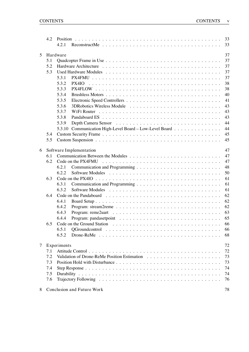
CONTENTS
CONTENTS v
4.2 Position .
. . . . . . . . . . . . .
4.2.1 ReconstructMe . . . . . .
. . . . . . . . . . . . .
. . . . . . . . . . . . .
. . . . . . . . . . . . .
. . . . . . . . . . . . .
. . .
. . .
5 Hardware
. . . . . . . . . . . . .
. . .
. . . . . . . . . . . . .
5.1 Quadcopter Frame in Use . . . . .
. . . . . . . . . . . . . . . .
. . . . . . . . . . . . .
5.2 Hardware Architecture . . . . . .
. . . . . . . . . . . . . . . .
. . . . . . . . . . . . .
5.3 Used Hardware Modules . . . . .
. . . . . . . . . . . . .
. . .
. . . . . . . . . . . . .
PX4FMU . . . . . . . . .
5.3.1
. . .
. . . . . . . . . . . . .
. . . . . . . . . . . . .
PX4IO . . . . . . . . . .
5.3.2
. . .
. . . . . . . . . . . . .
. . . . . . . . . . . . .
5.3.3
PX4FLOW . . . . . . . .
. . . . . . . . . . . . .
. . .
. . . . . . . . . . . . .
5.3.4 Brushless Motors . . . . .
. . .
. . . . . . . . . . . . .
5.3.5 Electronic Speed Controllers . . . . . . . . . . . .
. . .
. . . . . . . . . . . . .
5.3.6
. . . . . . . . . . .
. . .
. . . . . . . . . . . . .
. . . . . . . . . . . . .
5.3.7 WIFI Router
. . . . . . . . . . . . .
. . .
5.3.8
. . . . . . . . . . . . .
. . .
5.3.9 Depth Camera Sensor
. . . . . . . . . . . . .
. . . . . . . . . . . . .
. . .
5.3.10 Communication High-Level Board – Low-Level Board . . . . . . . . . . .
. . .
. . . . . . . . . . . . .
. . . . . . . . . . . . .
. . .
. . . . . . .
Pandaboard ES . . . . . .
. .
5.4 Custom Security Frame . . . . . .
5.5 Custom Suspension . . . . . . . .
. . . . . . . . . . . . .
. . . . . . . . . . . . .
3DRobotics Wireless Module
6 Software Implementation
Software Modules
Software Modules
. . . .
6.3 Code on the PX4IO . . . . . . . .
6.1 Communication Between the Modules . . . . . . . . . . .
. . . . . . . . . . . . .
6.2 Code on the PX4FMU . . . . . .
6.2.1 Communication and Programming . . . . . . . . .
. . . . . . . . . . . . .
6.2.2
. . . . . . . . . . . . .
6.3.1 Communication and Programming . . . . . . . . .
. . . . . . . . . . . . .
6.3.2
. . . . . . . . . . . . .
. . . . . . . . . . . . .
. . . . . . . . . . . . .
. . . . . . . . . . . . .
. . . . . . . . . . . . .
. . . . . . . . . . . . .
. . . . . . . . . . . . .
. . . . . . . . . . . . .
. . . .
6.4 Code on the Pandaboard . . . . .
6.4.1 Board Setup . . . . . . . .
Program: stream2reme . .
6.4.2
. . .
Program: reme2uart
6.4.3
6.4.4
Program: pandasetpoint
.
6.5 Code on the Ground Station . . .
6.5.1 QGroundcontrol
. . . . .
6.5.2 Drone-ReMe . . . . . . .
. . .
. . . . . . . . . . . . .
. . .
. . . . . . . . . . . . .
. . .
. . . . . . . . . . . . .
. . .
. . . . . . . . . . . . .
. . .
. . . . . . . . . . . . .
. . .
. . . . . . . . . . . . .
. . . . . . . . . . . . .
. . .
. . . . . . . . . . . . . . . .
. . . . . . . . . . . . .
. . .
. . .
. . . . . . . . . . . . .
. . .
. . . . . . . . . . . . .
. . .
. . . . . . . . . . . . .
. . . . . . . . . . . . .
. . .
. . .
. . . . . . . . . . . . .
. . . . . . . . . . . . .
. . .
7 Experiments
7.1 Attitude Control . . . . . . . . . .
. . . . . . . . . . . . .
7.2 Validation of Drone-ReMe Position Estimation . . . . . .
7.3 Position Hold with Disturbance . .
. . . . . . . . . . . . .
. . . . . . . . . . . . .
7.4 Step Response . . . . . . . . . . .
. . . . . . . . . . . . .
7.5 Durability . . . . . . . . . . . . .
7.6 Trajectory Following . . . . . . .
. . . . . . . . . . . . .
. . . . . . . . . . . . .
. . . . . . . . . . . . .
. . . . . . . . . . . . .
. . . . . . . . . . . . .
. . . . . . . . . . . . .
. . . . . . . . . . . . .
. . .
. . .
. . .
. . .
. . .
. . .
8 Conclusion and Future Work
33
33
37
37
37
37
37
38
38
40
41
43
43
43
44
44
45
45
47
47
47
48
50
61
61
61
62
62
62
63
65
66
66
68
72
72
73
73
74
74
76
78
�
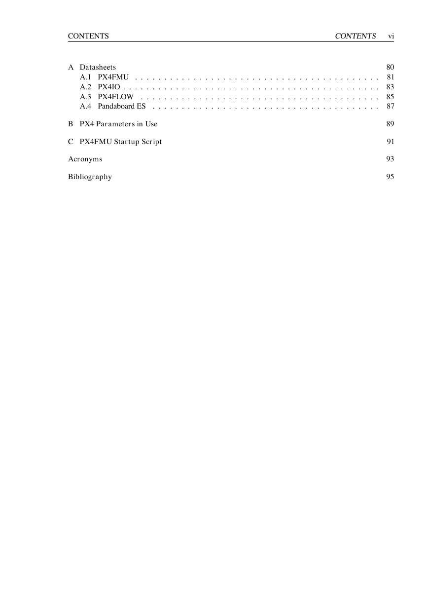
CONTENTS
A Datasheets
A.1 PX4FMU . . . . . . . . . . . . .
A.2 PX4IO . .
. . . . . . . . . . . . .
A.3 PX4FLOW . . . . . . . . . . . .
A.4 Pandaboard ES . . . . . . . . . .
. . . . . . . . . . . . .
. . . . . . . . . . . . .
. . . . . . . . . . . . .
. . . . . . . . . . . . .
. . . . . . . . . . . . .
. . . . . . . . . . . . .
. . . . . . . . . . . . .
. . . . . . . . . . . . .
. . .
. . .
. . .
. . .
B PX4 Parameters in Use
C PX4FMU Startup Script
Acronyms
Bibliography
CONTENTS vi
80
81
83
85
87
89
91
93
95
�




 2023年江西萍乡中考道德与法治真题及答案.doc
 2012年重庆南川中考生物真题及答案.doc
 2013年江西师范大学地理学综合及文艺理论基础考研真题.doc
 2020年四川甘孜小升初语文真题及答案I卷.doc
 2020年注册岩土工程师专业基础考试真题及答案.doc
 2023-2024学年福建省厦门市九年级上学期数学月考试题及答案.doc
 2021-2022学年辽宁省沈阳市大东区九年级上学期语文期末试题及答案.doc
 2022-2023学年北京东城区初三第一学期物理期末试卷及答案.doc
 2018上半年江西教师资格初中地理学科知识与教学能力真题及答案.doc
 2012年河北国家公务员申论考试真题及答案-省级.doc
 2020-2021学年江苏省扬州市江都区邵樊片九年级上学期数学第一次质量检测试题及答案.doc
 2022下半年黑龙江教师资格证中学综合素质真题及答案.doc