Introduction
General
Naming Convention
Acronyms and Terms
References
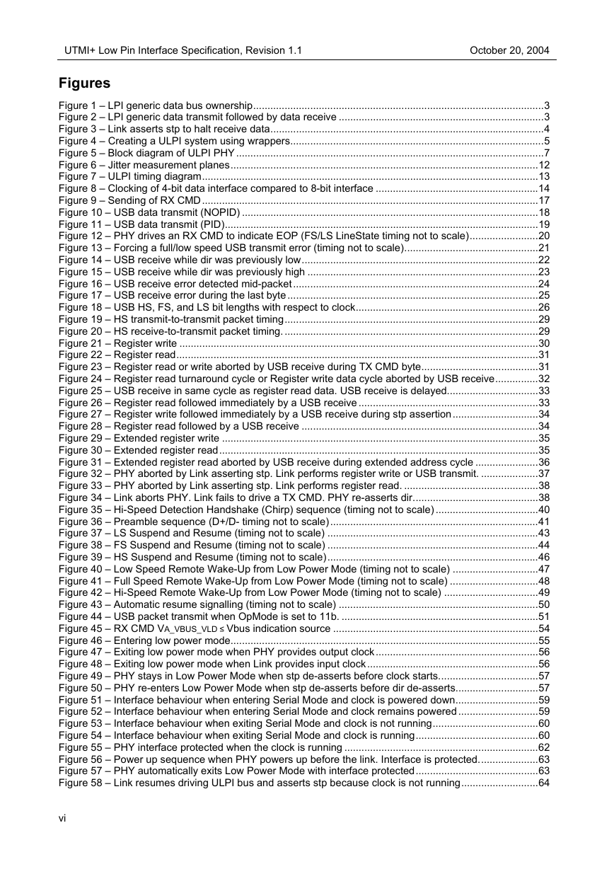
Generic Low Pin Interface
General
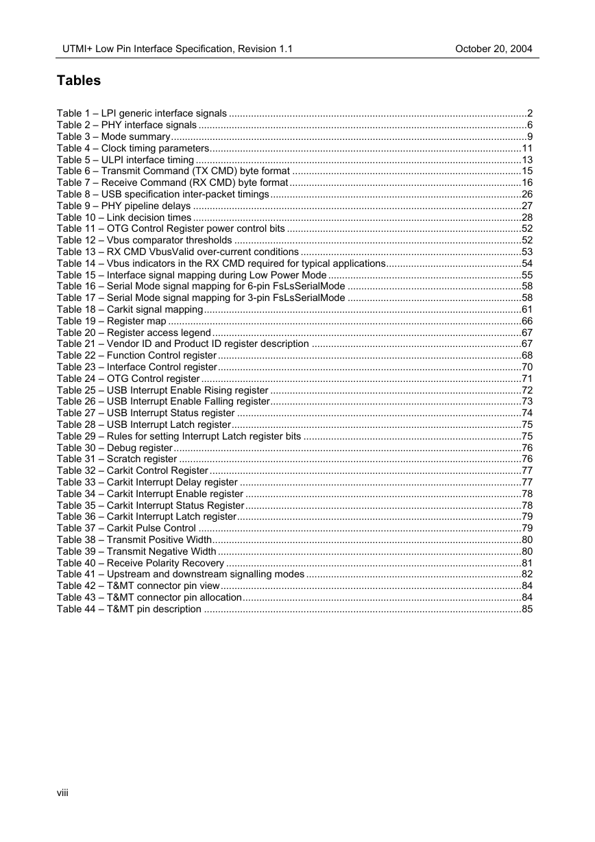
Signals
Protocol
Bus Ownership
Transferring Data
Aborting Data
UTMI+ Low Pin Interface
General
Signals
Block Diagram
ULPI PHY Wrapper
Crystal Oscillator and PLL
General Biasing
DrvVbusExternal and ExternalVbusIndicator
Power-On-Reset
Carkit Option
Modes
Power On and Reset
Interrupt Event Notification
Timing
Clock
Output Clock
Input Clock (optional)
Input Clock Jitter
Control and Data
4-bit Data Clocking (optional)
Synchronous Mode
ULPI Command Bytes
Transmit Command Byte (TX CMD)
Receive Command Byte (RX CMD)
When to send an RX CMD
USB Packets
USB Data Transmit (NOPID)
USB Packet Transmit (PID)
USB Transmit Error
USB Packet Receive
USB Receive Error
USB Packet Timing
USB Inter-packet delay and Packet timeout
PHY Pipeline Delays
Link Decision Time
Inter-packet Timing Diagrams
Register Operations
Immediate Register Read and Write
Immediate Register Read and Write Aborted by USB Receive
Back-to-back Immediate Register Read/Write and USB Receive
Extended Register Read and Write
Extended Register Read aborted by and back-to-back with USB Receive
Aborting ULPI Transfers
Link aborted by PHY
PHY aborted by Link
USB Operations
Hi-Speed Detection Handshake (Chirp)
Preamble
USB Suspend and Resume
Low Speed Suspend and Resume
Full Speed Suspend and Resume
Hi-Speed Suspend and Resume
Remote Wake-up
Low Speed Remote Wake-up
Full Speed Remote Wake-up
Hi-Speed Remote Wake-up
AutoResume
Peripheral Connect and Disconnect Detection
No SYNC and EOP Generation (OpMode 11b) (Optional)
Vbus Power Control (internal and external)
OTG Operations
Session Request Protocol (SRP)
Host Negotiation Protocol (HNP) (Optional)
VBUS Comparator Thresholds
Threshold Range
Typical Application
RxCmd VBUS Valid source
SessEnd
Low Power Mode
Data Line Definition For Low Power Mode
Entering Low Power Mode
Exiting Low Power Mode
False Resume Rejection
Full Speed / Low Speed Serial Mode (Optional)
Data Line Definition For FsLsSerialMode
Entering FsLsSerialMode
Exiting FsLsSerialMode
Carkit Mode (Optional)
Safeguarding PHY Input Signals
Registers
Register Map
Immediate Register Set
Vendor ID and Product ID
Function Control
Interface Control
OTG Control
USB Interrupt Enable Rising
USB Interrupt Enable Falling
USB Interrupt Status
USB Interrupt Latch
Debug
Scratch Register
Carkit Control
Carkit Interrupt Delay
Carkit Interrupt Enable
Carkit Interrupt Status
Carkit Interrupt Latch
Carkit Pulse Control
Transmit Positive Width
Transmit Negative Width
Receive Polarity Recovery
Reserved
Access Extended Register Set
Vendor-specific
Extended Register Set
Register Settings for all Upstream and Downstream signalling modes
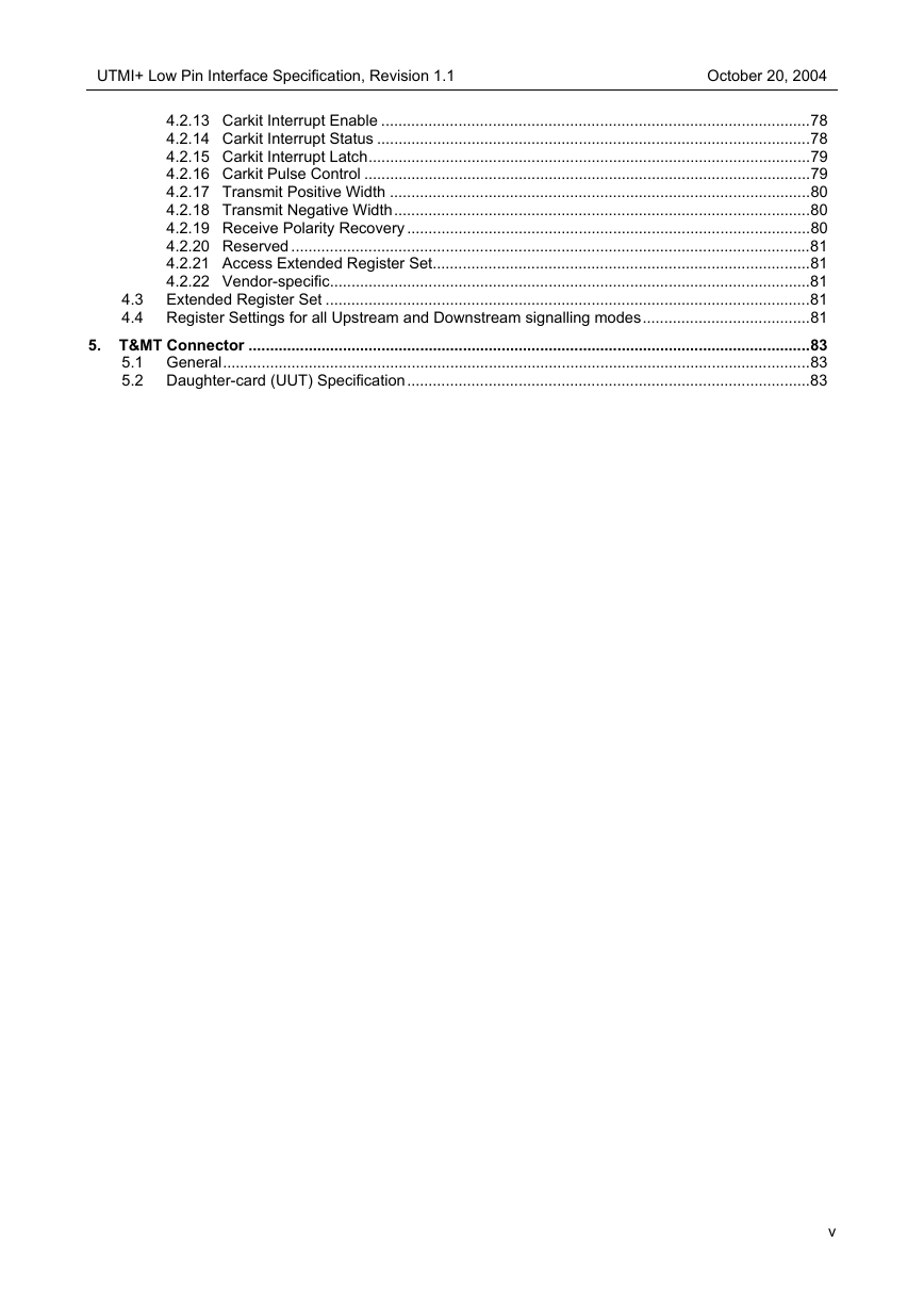
T&MT Connector
General
Daughter-card (UUT) Specification


 2023年江西萍乡中考道德与法治真题及答案.doc
 2012年重庆南川中考生物真题及答案.doc
 2013年江西师范大学地理学综合及文艺理论基础考研真题.doc
 2020年四川甘孜小升初语文真题及答案I卷.doc
 2020年注册岩土工程师专业基础考试真题及答案.doc
 2023-2024学年福建省厦门市九年级上学期数学月考试题及答案.doc
 2021-2022学年辽宁省沈阳市大东区九年级上学期语文期末试题及答案.doc
 2022-2023学年北京东城区初三第一学期物理期末试卷及答案.doc
 2018上半年江西教师资格初中地理学科知识与教学能力真题及答案.doc
 2012年河北国家公务员申论考试真题及答案-省级.doc
 2020-2021学年江苏省扬州市江都区邵樊片九年级上学期数学第一次质量检测试题及答案.doc
 2022下半年黑龙江教师资格证中学综合素质真题及答案.doc