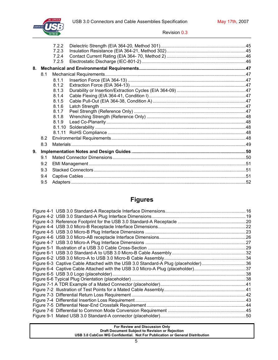
1. Introduction
1.1 Scope
1.2 Objective
2. Acronyms and Terms
3. Significant Features
3.1.1 USB 3.0 Standard-A Connector
3.1.2 USB 3.0 Micro-B Connector
3.1.3 USB 3.0 Micro-AB and USB 3.0 Micro-A Connectors
4. Connector Mating Interfaces
4.2.1 Interface Definition
4.2.2 Pin Assignments and Description
4.2.3 USB 3.0 Standard-A Receptacle Color Code
4.3.1 Interface Definition
4.3.2 Pin Assignments and Description
4.3.3 Color Coding
5. Cable Construction and Wire Assignments
6. Cable Assemblies
6.1.1 Drawing
6.1.2 Wiring
6.2.1 Overmold Dimensions
6.2.2 Wiring
7. Electrical Requirements
7.1.1 Raw Cable
7.1.1.1 Characteristic Impedance
7.1.1.2 Intra-Pair Skew
7.1.1.3 Differential Attenuation
7.1.2 Mated Connector
7.1.3 Mated Cable Assemblies
7.1.3.1 Differential Return Loss (EIA-360-108)
7.1.3.2 Differential Insertion Loss (EIA-360-101)
7.1.3.3 Differential Near-End Crosstalk (EIA-360-90)
7.1.3.4 Differential to Common Mode Conversion
7.2.1 Low Level Contact Resistance (EIA 364-23B)
7.2.2 Dielectric Strength (EIA 364-20, Method 301)
7.2.3 Insulation Resistance (EIA 364-21, Method 302)
7.2.4 Contact Current Rating (EIA 364- 70, Method 2)
7.2.5 Electrostatic Discharge (IEC-801-2)
8. Mechanical and Environmental Requirements
8.1.1 Insertion Force (EIA 364-13)
8.1.2 Extraction Force (EIA 364-13)
8.1.3 Durability or Insertion/Extraction Cycles (EIA 364-09)
8.1.4 Cable Flexing (EIA 364-41, Condition I)
8.1.5 Cable Pull-Out (EIA 364-38, Condition A)
8.1.6 Latch Strength
8.1.7 Peel Strength (Reference Only)
8.1.8 Wrenching Strength (Reference Only)
8.1.9 Lead Co-Planarity
8.1.10 Solderability
8.1.11 RoHS Compliance
9. Implementation Notes and Design Guides


 2023年江西萍乡中考道德与法治真题及答案.doc
 2012年重庆南川中考生物真题及答案.doc
 2013年江西师范大学地理学综合及文艺理论基础考研真题.doc
 2020年四川甘孜小升初语文真题及答案I卷.doc
 2020年注册岩土工程师专业基础考试真题及答案.doc
 2023-2024学年福建省厦门市九年级上学期数学月考试题及答案.doc
 2021-2022学年辽宁省沈阳市大东区九年级上学期语文期末试题及答案.doc
 2022-2023学年北京东城区初三第一学期物理期末试卷及答案.doc
 2018上半年江西教师资格初中地理学科知识与教学能力真题及答案.doc
 2012年河北国家公务员申论考试真题及答案-省级.doc
 2020-2021学年江苏省扬州市江都区邵樊片九年级上学期数学第一次质量检测试题及答案.doc
 2022下半年黑龙江教师资格证中学综合素质真题及答案.doc