An Introduction to HFSS-IE
Workshop 6.1 – HFSS-IE
Example: HFSS to HFSS-IE Datalink
ANSYS, Inc. Proprietary
ANSYS, Inc. Proprietary
© 2009 ANSYS, Inc. All rights reserved.
© 2009 ANSYS, Inc. All rights reserved.
WS06.1-1
1-1
February 23, 2009
January 20, 2010
Inventory #002593
Inventory #002704
�
Introduction
An Introduction to HFSS-IE
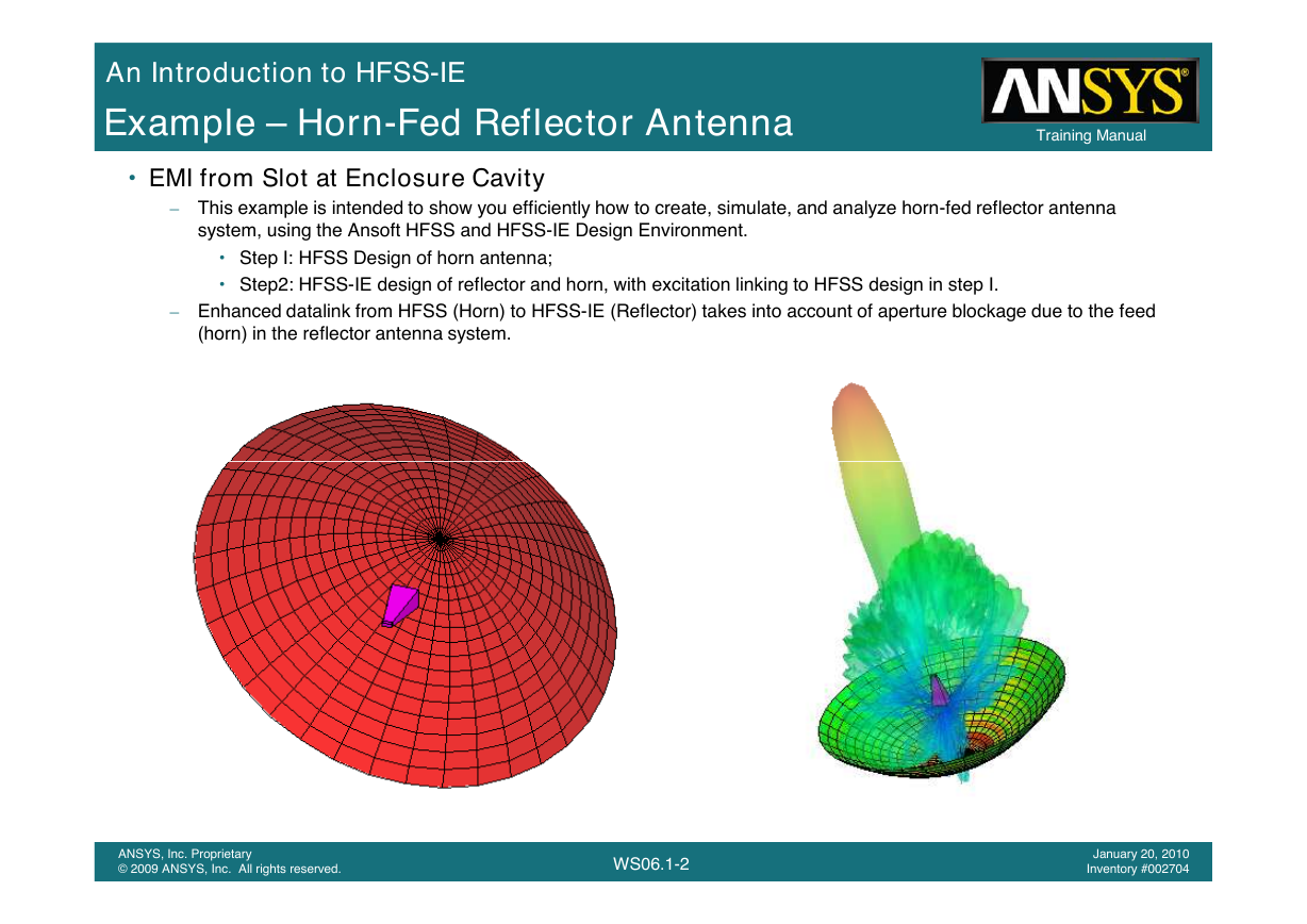
Example – Horn-Fed Reflector Antenna
• EMI from Slot at Enclosure Cavity
Training Manual
Training Manual
– This example is intended to show you efficiently how to create, simulate, and analyze horn-fed reflector antenna
system, using the Ansoft HFSS and HFSS-IE Design Environment.
• Step I: HFSS Design of horn antenna;
• Step2: HFSS-IE design of reflector and horn, with excitation linking to HFSS design in step I.
– Enhanced datalink from HFSS (Horn) to HFSS-IE (Reflector) takes into account of aperture blockage due to the feed
(horn) in the reflector antenna system.
ANSYS, Inc. Proprietary
ANSYS, Inc. Proprietary
© 2009 ANSYS, Inc. All rights reserved.
© 2009 ANSYS, Inc. All rights reserved.
WS06.1-2
1-2
February 23, 2009
January 20, 2010
Inventory #002593
Inventory #002704
�
Introduction
An Introduction to HFSS-IE
Getting Started
• Getting Started of HFSS for Horn Antenna
Training Manual
Training Manual
• Launching Ansoft HFSS
– To access Ansoft HFSS, click the Microsoft Start button, select Programs, and select the Ansoft, HFSS 12 program
group. Click HFSS 12.
• Setting Tool Options
– Note: In order to follow the steps outlined in this example, verify that the following tool options are set :
– Select the menu item Tools > Options > HFSS-IE Options
• Click the General tab
– Use Wizards for data input when creating new boundaries: Checked
– Duplicate boundaries with geometry: Checked
• Click the OK button
– Select the menu item Tools > Options > Modeler Options.
• Click the Operation tab
– Automatically cover closed polylines: Checked
• Click the Drawing tab
– Edit property of new primitives: Checked
• Click the OK button
ANSYS, Inc. Proprietary
ANSYS, Inc. Proprietary
© 2009 ANSYS, Inc. All rights reserved.
© 2009 ANSYS, Inc. All rights reserved.
WS06.1-3
1-3
February 23, 2009
January 20, 2010
Inventory #002593
Inventory #002704
�
Introduction
An Introduction to HFSS-IE
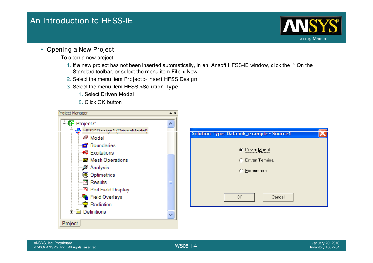
• Opening a New Project
– To open a new project:
Training Manual
Training Manual
1. If a new project has not been inserted automatically, In an Ansoft HFSS-IE window, click the On the
Standard toolbar, or select the menu item File > New.
2. Select the menu item Project > Insert HFSS Design
3. Select the menu item HFSS >Solution Type
1. Select Driven Modal
2. Click OK button
ANSYS, Inc. Proprietary
ANSYS, Inc. Proprietary
© 2009 ANSYS, Inc. All rights reserved.
© 2009 ANSYS, Inc. All rights reserved.
WS06.1-4
1-4
February 23, 2009
January 20, 2010
Inventory #002593
Inventory #002704
�
Introduction
An Introduction to HFSS-IE
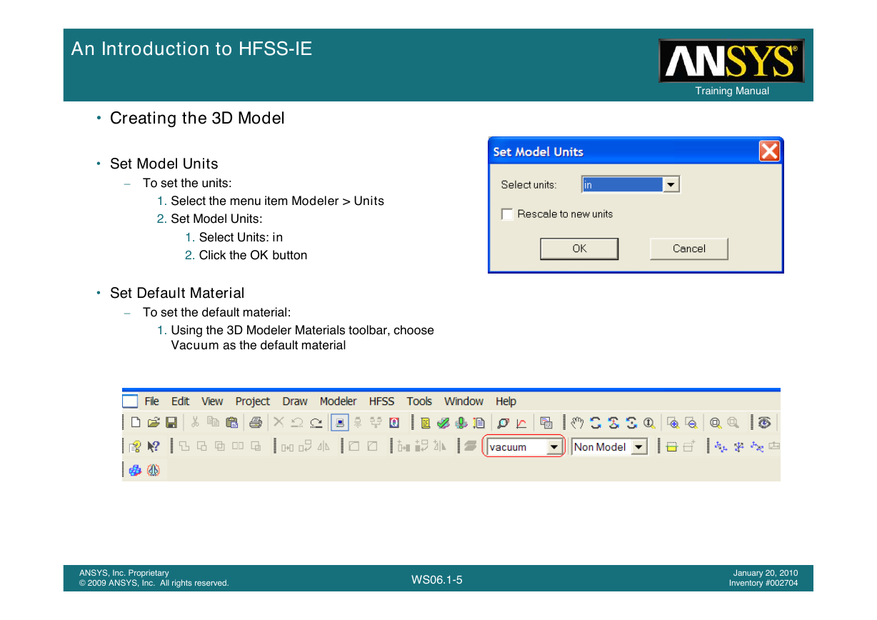
• Creating the 3D Model
• Set Model Units
– To set the units:
1. Select the menu item Modeler > Units
2. Set Model Units:
1. Select Units: in
2. Click the OK button
• Set Default Material
– To set the default material:
– To set the default material:
1. Using the 3D Modeler Materials toolbar, choose
Vacuum as the default material
Training Manual
Training Manual
ANSYS, Inc. Proprietary
ANSYS, Inc. Proprietary
© 2009 ANSYS, Inc. All rights reserved.
© 2009 ANSYS, Inc. All rights reserved.
WS06.1-5
1-5
February 23, 2009
January 20, 2010
Inventory #002593
Inventory #002704
�
Introduction
An Introduction to HFSS-IE
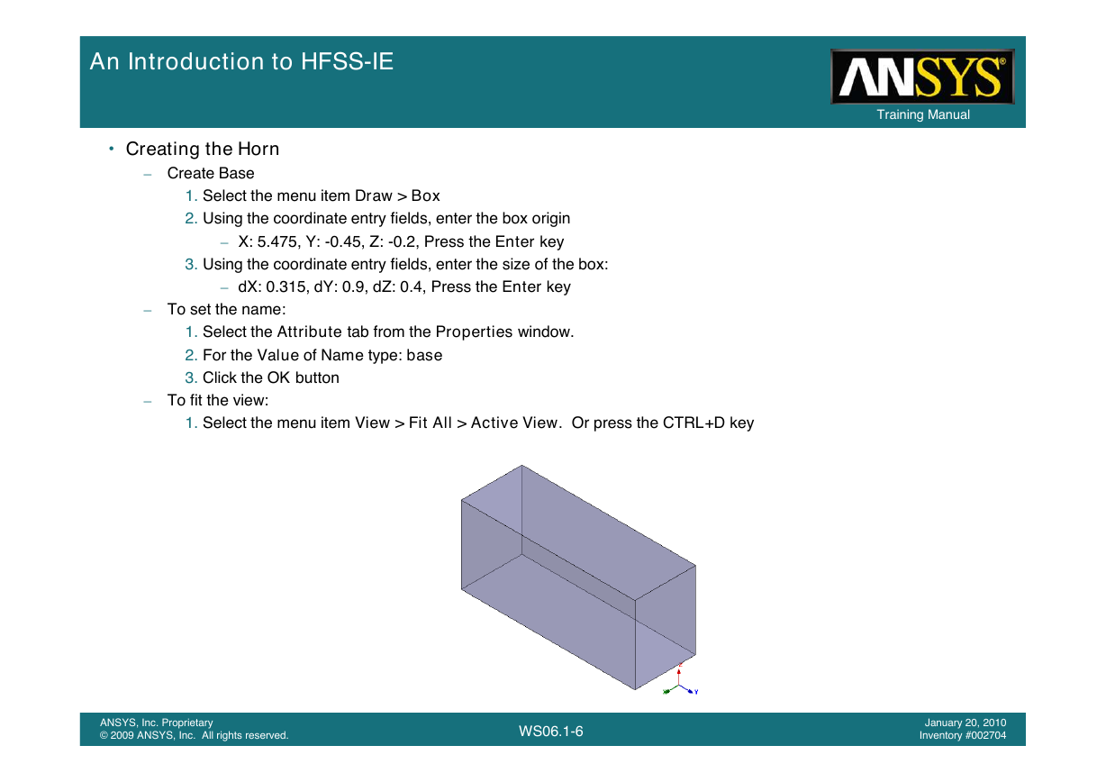
• Creating the Horn
– Create Base
1. Select the menu item Draw > Box
2. Using the coordinate entry fields, enter the box origin
– X: 5.475, Y: -0.45, Z: -0.2, Press the Enter key
3. Using the coordinate entry fields, enter the size of the box:
– dX: 0.315, dY: 0.9, dZ: 0.4, Press the Enter key
– To set the name:
1. Select the Attribute tab from the Properties window.
2. For the Value of Name type: base
3. Click the OK button
– To fit the view:
1. Select the menu item View > Fit All > Active View. Or press the CTRL+D key
Training Manual
Training Manual
ANSYS, Inc. Proprietary
ANSYS, Inc. Proprietary
© 2009 ANSYS, Inc. All rights reserved.
© 2009 ANSYS, Inc. All rights reserved.
WS06.1-6
1-6
February 23, 2009
January 20, 2010
Inventory #002593
Inventory #002704
�
Training Manual
Training Manual
Introduction
An Introduction to HFSS-IE
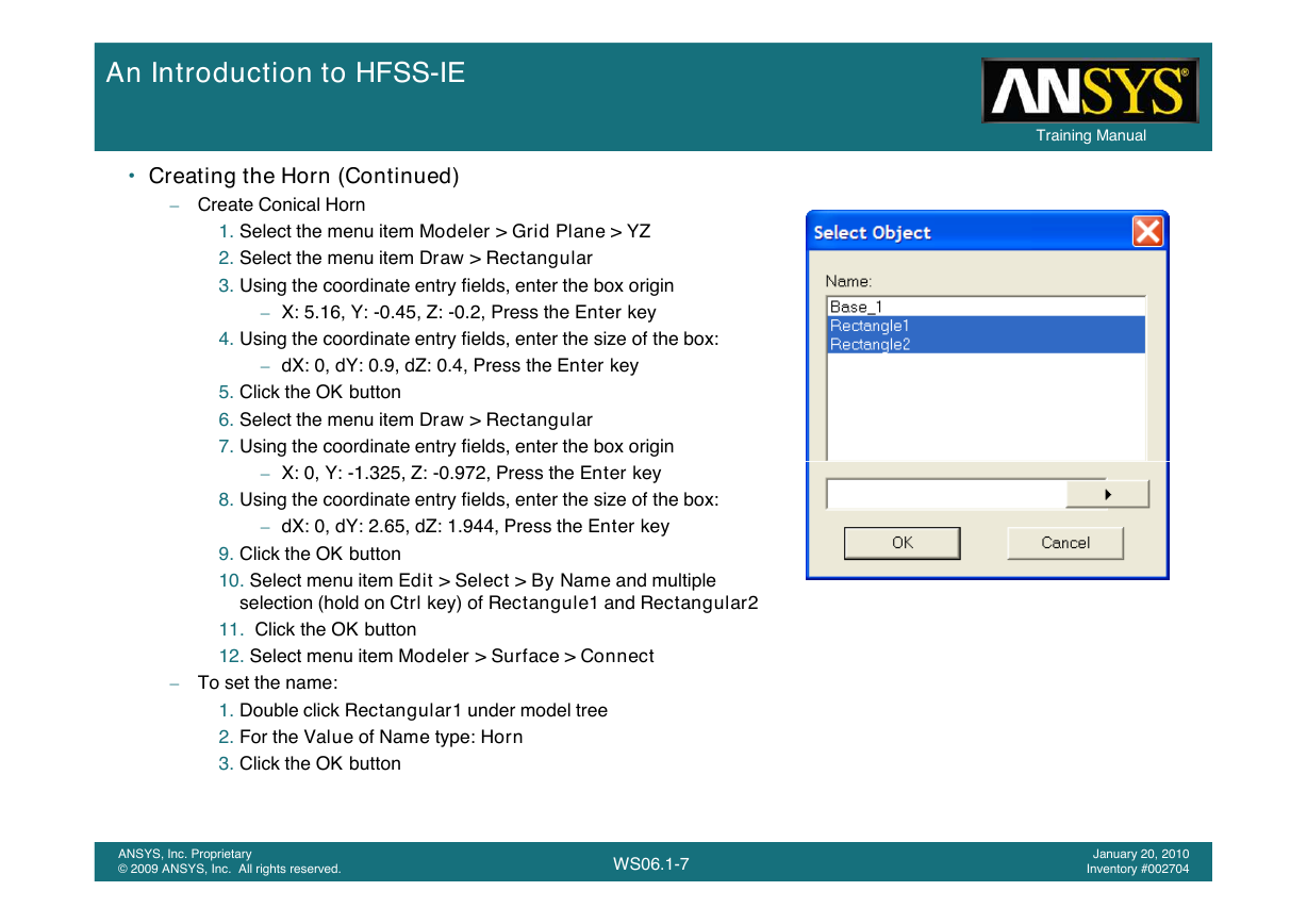
• Creating the Horn (Continued)
– Create Conical Horn
1. Select the menu item Modeler > Grid Plane > YZ
2. Select the menu item Draw > Rectangular
3. Using the coordinate entry fields, enter the box origin
– X: 5.16, Y: -0.45, Z: -0.2, Press the Enter key
4. Using the coordinate entry fields, enter the size of the box:
– dX: 0, dY: 0.9, dZ: 0.4, Press the Enter key
5. Click the OK button
6. Select the menu item Draw > Rectangular
7. Using the coordinate entry fields, enter the box origin
– X: 0, Y: -1.325, Z: -0.972, Press the Enter key
8. Using the coordinate entry fields, enter the size of the box:
– dX: 0, dY: 2.65, dZ: 1.944, Press the Enter key
9. Click the OK button
10. Select menu item Edit > Select > By Name and multiple
selection (hold on Ctrl key) of Rectangule1 and Rectangular2
11. Click the OK button
12. Select menu item Modeler > Surface > Connect
– To set the name:
1. Double click Rectangular1 under model tree
2. For the Value of Name type: Horn
3. Click the OK button
ANSYS, Inc. Proprietary
ANSYS, Inc. Proprietary
© 2009 ANSYS, Inc. All rights reserved.
© 2009 ANSYS, Inc. All rights reserved.
WS06.1-7
1-7
February 23, 2009
January 20, 2010
Inventory #002593
Inventory #002704
�
Training Manual
Training Manual
Introduction
An Introduction to HFSS-IE
• Creating the Horn (Continued)
– Create Conical Horn
1. Select menu item Edit > Select > By Name
2. Multiple selection (hold on Ctrl key) of Horn and Base
3. Click the OK button
4. Select menu item Modeler > Boolean> Unite
5. Select menu item Edit > Select > Faces
6. Select menu item Edit > Select > By Name
7. Select Horn and Multiply select first 9 Face IDs
8. Click the OK button
9. Select menu item Modeler > Surface > Detach Faces
10.Select menu item Edit > Select > Objects
11.Select menu item Edit > Select > By Name
12. Select Horn and Horn_Detach1, 2, 3, 4, 7, 8,9
13. Click the OK button
14. Select menu item Modeler > Boolean> Unite
15. Double click Horn_detach5 under model tree
16.For the Value of Name type: Horn_Port
17.Click the OK button
18. Select menu item HFSS >Boundaries >Assign >Perfect E
19. Click the OK button
ANSYS, Inc. Proprietary
ANSYS, Inc. Proprietary
© 2009 ANSYS, Inc. All rights reserved.
© 2009 ANSYS, Inc. All rights reserved.
WS06.1-8
1-8
February 23, 2009
January 20, 2010
Inventory #002593
Inventory #002704
�


 2023年江西萍乡中考道德与法治真题及答案.doc
 2012年重庆南川中考生物真题及答案.doc
 2013年江西师范大学地理学综合及文艺理论基础考研真题.doc
 2020年四川甘孜小升初语文真题及答案I卷.doc
 2020年注册岩土工程师专业基础考试真题及答案.doc
 2023-2024学年福建省厦门市九年级上学期数学月考试题及答案.doc
 2021-2022学年辽宁省沈阳市大东区九年级上学期语文期末试题及答案.doc
 2022-2023学年北京东城区初三第一学期物理期末试卷及答案.doc
 2018上半年江西教师资格初中地理学科知识与教学能力真题及答案.doc
 2012年河北国家公务员申论考试真题及答案-省级.doc
 2020-2021学年江苏省扬州市江都区邵樊片九年级上学期数学第一次质量检测试题及答案.doc
 2022下半年黑龙江教师资格证中学综合素质真题及答案.doc