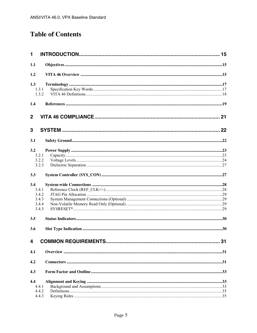
1 Introduction
1.1 Objectives
1.2 VITA 46 Overview
1.3 Terminology
1.3.1 Specification Key Words
1.3.2 VITA 46 Definitions
1.4 References
2 VITA 46 Compliance
3 System
3.1 Safety Ground
3.2 Power Supply
3.2.1 Capacity
3.2.1.1 Plug-In Module/Backplane Power Return Current Capacity
3.2.2 Voltage Levels
3.2.2.1 3U Primary Power Input
3.2.2.2 6U Primary Power Input
3.2.2.3 Auxiliary Power Inputs
3.2.2.3.1 3.3V_AUX
3.2.2.3.2 12V Auxiliary Supplies
3.2.3 Dielectric Separation
3.3 System Controller (SYS_CON)
3.4 System-wide Connections
3.4.1 Reference Clock (REF_CLK+/-)
3.4.1.1 Reference Clock Generator (Optional)
3.4.2 JTAG Pin Allocation
3.4.3 System Management Connections (Optional)
3.4.4 Non-Volatile Memory Read Only (Optional)
3.4.5 SYSRESET*
3.5 Status Indicators
3.6 Slot Type Indication
4 Common Requirements
4.1 Overview
4.2 Connectors
4.3 Form Factor and Outline
4.4 Alignment and Keying
4.4.1 Background and Assumptions
4.4.1.1 Philosophy
4.4.1.2 Backplane Key
4.4.1.3 Plug-in Module Key
4.4.2 Definitions
4.4.3 Keying Rules
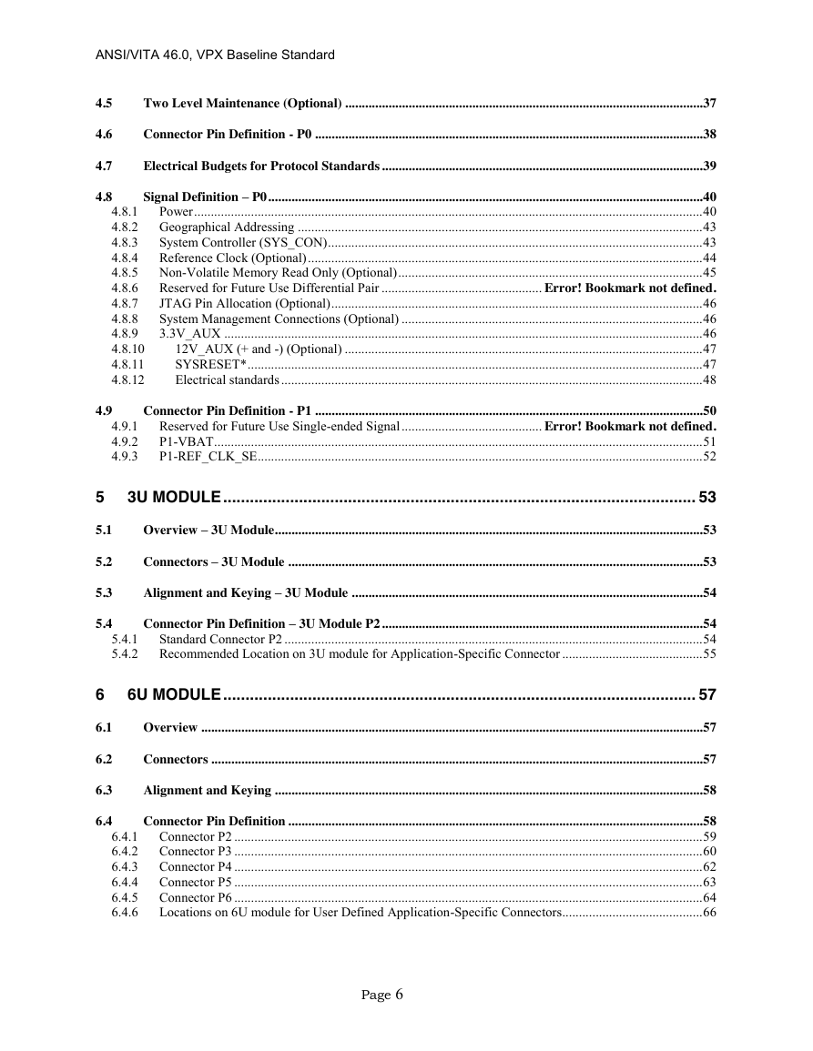
4.5 Two Level Maintenance (Optional)
4.6 Connector Pin Definition - P0
4.7 Electrical Budgets for Protocol Standards
4.8 Signal Definition – P0
4.8.1 Power
4.8.1.1 High Voltage Power Inputs
4.8.1.1.1 6U High Voltage Power Input
4.8.1.1.2 6U Use of 48V for High Voltage Power Input
4.8.1.1.3 6U Use of 12V for High Voltage Power Input
4.8.1.1.4 3U High Voltage Power Input
4.8.1.2 Vs3
4.8.2 Geographical Addressing
4.8.3 System Controller (SYS_CON)
4.8.4 Reference Clock (Optional)
4.8.4.1 Reference Clock Generator (Optional)
4.8.4.2 Reference Clock Receiver (Optional)
4.8.5 Non-Volatile Memory Read Only (Optional)
4.8.6 Auxiliary Clock
4.8.7 JTAG Pin Allocation (Optional)
4.8.8 System Management Connections (Optional)
4.8.9 3.3V_AUX
4.8.10 12V_AUX (+ and -) (Optional)
4.8.11 SYSRESET*
4.8.12 Electrical standards
4.8.12.1 Low Current Open Collector Electrical Characteristics
4.8.12.2 High Current Open Collector Electrical Characteristics
4.8.12.3 Totem Pole Electrical Characteristics
4.8.12.4 Power Supply Monitor Electrical Characteristics
4.9 Connector Pin Definition - P1
4.9.1 Bussed GPIO (GDiscrete1)
4.9.2 P1-VBAT
4.9.3 P1-REF_CLK_SE
5 3U Module
5.1 Overview – 3U Module
5.2 Connectors – 3U Module
5.3 Alignment and Keying – 3U Module
5.4 Connector Pin Definition – 3U Module P2
5.4.1 Standard Connector P2
5.4.2 Recommended Location on 3U module for Application-Specific Connector
5.4.2.1 Differential Connector Allocation
5.4.2.2 Single-ended Connector Allocation
6 6U Module
6.1 Overview
6.2 Connectors
6.3 Alignment and Keying
6.4 Connector Pin Definition
6.4.1 Connector P2
6.4.1.1 Differential Connector Allocation
6.4.1.2 Single-ended Connector Allocation
6.4.2 Connector P3
6.4.2.1 Differential Connector Allocation
6.4.2.2 Single-ended Connector Allocation
6.4.3 Connector P4
6.4.3.1 Differential Connector Allocation
6.4.3.2 Single-ended Connector Allocation
6.4.4 Connector P5
6.4.4.1 Differential Connector Allocation
6.4.4.2 Single-ended Connector Allocation
6.4.5 Connector P6
6.4.5.1 Differential Connector Allocation
6.4.5.2 Single-ended Connector Allocation
6.4.6 Locations on 6U module for User Defined Application-Specific Connectors
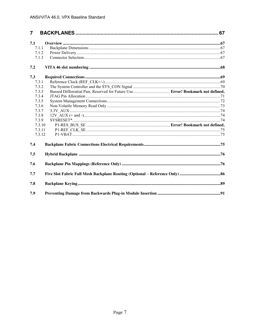
7 Backplanes
7.1 Overview
7.1.1 Backplane Dimensions
7.1.2 Power Delivery
7.1.3 Connector Selection
7.2 VITA 46 slot numbering
7.3 Required Connections
7.3.1 Reference Clock (REF_CLK+/-)
7.3.2 The System Controller and the SYS_CON Signal
7.3.3 Auxiliary Clock
7.3.4 JTAG Pin Allocation
7.3.5 System Management Connections
7.3.6 Non-Volatile Memory Read Only
7.3.7 3.3V_AUX
7.3.8 12V_AUX (+ and -)
7.3.9 SYSRESET*
7.3.10 Bussed GPIO (GDiscrete1)
7.3.11 P1-REF_CLK_SE
7.3.12 P1-VBAT
7.4 Backplane Fabric Connections Electrical Requirements
7.5 Hybrid Backplane
7.6 Backplane Pin Mappings (Reference Only)
7.7 Five Slot Fabric Full Mesh Backplane Routing (Optional – Reference Only)
7.8 Backplane Keying
7.9 Preventing Damage from Backwards Plug-in Module Insertion
Appendix A Plug-in Module Assembly Drawings
Appendix B Backplane Printed Circuit Board Fabrication Drawings
Appendix C Plug-in Module Printed Circuit Board Fabrication Drawings
Appendix D Design Concepts to Prevent Damage from Backwards Air Cooled Plug-in Module Insertion



 2023年江西萍乡中考道德与法治真题及答案.doc
 2012年重庆南川中考生物真题及答案.doc
 2013年江西师范大学地理学综合及文艺理论基础考研真题.doc
 2020年四川甘孜小升初语文真题及答案I卷.doc
 2020年注册岩土工程师专业基础考试真题及答案.doc
 2023-2024学年福建省厦门市九年级上学期数学月考试题及答案.doc
 2021-2022学年辽宁省沈阳市大东区九年级上学期语文期末试题及答案.doc
 2022-2023学年北京东城区初三第一学期物理期末试卷及答案.doc
 2018上半年江西教师资格初中地理学科知识与教学能力真题及答案.doc
 2012年河北国家公务员申论考试真题及答案-省级.doc
 2020-2021学年江苏省扬州市江都区邵樊片九年级上学期数学第一次质量检测试题及答案.doc
 2022下半年黑龙江教师资格证中学综合素质真题及答案.doc