logo资料库

PICMG+3.0+R3.PDF

第1页 / 共656页
第2页 / 共656页
第3页 / 共656页
第4页 / 共656页
第5页 / 共656页
第6页 / 共656页
第7页 / 共656页
第8页 / 共656页
资料共656页,剩余部分请下载后查看
PICMG® 3.0 Revision 3.0
AdvancedTCA® Base Specification
Introduction and objectives 1
1.1 Objective
1.1.1 Special word usage
1.1.2 Statement of compliance
1.2 Reference documents
1.2.1 Reference specifications
1.2.2 Contact information for reference organizations
1.2.3 Environment and regulatory documents
1.3 Name and logo usage
1.4 Signal naming conventions
1.5 Intellectual Property
1.6 Special terms and acronyms
1.7 Dimensions
Mechanical 2
2.1 Mechanical overview
2.1.1 Tolerances
2.1.2 Standard orientation
2.1.3 Horizontal orientation
2.1.4 Drawing symbols
2.1.5 Keepout zones
2.2 Front Board assembly
2.2.1 Front Board PCB dimensions
2.2.2 Front Board PCB thickness
2.2.3 Front Board pitch and offset
2.2.4 Component height
2.2.4.1 Front Board warpage
2.2.4.2 Front Board stiffening
2.2.5 ESD Strip
2.2.6 Front Board covers
2.2.7 Front Board Face Plate
2.2.7.1 Front Board Face Plate Handles
2.2.7.2 Front Board Face Plate Alignment and Safety Ground Pin
2.2.7.3 Front Board Face Plate retention screws
2.2.7.4 Front Board Filler Panels
2.2.8 Front Board Face Plate LEDs
2.2.8.1 General status LEDs
2.2.8.2 Application specific LEDs
2.2.9 Front Board Face Plate labels
2.2.9.1 AdvancedTCA® logo label and vendor logo label
2.2.9.2 Barcode label
2.2.10 Test dimensions
2.3 RTM assembly
2.3.1 RTM direct mate to Front Board
2.3.1.1 RTM PCB dimensions
2.3.1.2 RTM PCB thickness
2.3.1.3 RTM pitch and offset
2.3.1.4 RTM component height
2.3.1.5 RTM ESD Strip
2.3.1.6 RTM Covers
2.3.1.7 RTM Face Plate
2.3.1.8 RTM Face Plate LEDs
2.3.1.9 RTM Face Plate labels
2.3.1.10 RTM airflow requirements and direction
2.3.1.11 Zone 3 airflow seal
2.3.1.12 RTM Zone 3 keying
2.3.2 Zone 3 Cable Bulkhead
2.3.3 RTM connection to Zone 3 midplane
2.4 Zone 1, 2, and 3 connectors
2.4.1 Zone 1 Connector
2.4.1.1 Description
2.4.1.2 -48 VDC power circuit definitions
2.4.1.3 Metallic Test Bus circuits
2.4.1.4 Ringing Generator Bus circuit
2.4.1.5 Hardware platform management circuit definitions
2.4.2 Zone 2 Connectors
2.4.2.1 General description of Zone 2 Connectors
2.4.2.2 Pin numbering
2.4.2.3 Sequential mating
2.4.3 Zone 3 Connectors
2.4.3.1 General description
2.4.3.2 Zone 3 Connector envelope
2.4.3.3 Insertion force
2.4.3.4 Alignment allowances/gatherability
2.4.4 Front Board and RTM alignment/keying
2.4.4.1 Alignment overview
2.4.4.2 Keying overview
2.4.4.3 Zone 1 and Zone 2 keying/alignment
2.4.4.4 RTM alignment
2.4.4.5 Zone 3 alignment and keying
2.5 Backplanes
2.5.1 Description
2.5.2 Connector locations
2.6 Subrack
2.6.1 Subrack features
2.6.2 Backplane support bar
2.6.3 Subrack interface requirements for Front Boards
2.6.4 Guide Rail requirements
2.6.4.1 Front Board and RTM Guide Rail requirements
2.6.4.2 Logical Slot identification
2.6.4.3 ESD Clip position in the Guide Rails
2.6.5 Face Plate Alignment and Safety Ground Pin
2.6.6 Retention screw receptacle
2.6.7 Subrack EMC Gasketing requirements
2.6.8 Subrack load carrying capability
2.6.9 Subrack integrity tests
2.6.9.1 Subrack shock and vibration performance
2.6.9.2 Earthquake performance
2.6.9.3 Flammability
2.6.9.4 Shelf climatic test
2.6.9.5 Shelf atmosphere test
2.6.9.6 Insertion cycles
2.6.10 Physical Slot Numbering
2.7 Shelf
2.7.1 Shelf types
2.7.2 Shelf width and Shelf height
2.7.3 Shelf depth
2.7.4 Air filter provision
2.7.5 ESD wrist strap interface
2.7.6 Telco inputs and alarm outputs
2.7.6.1 Telco alarm information
2.7.6.2 Telco alarm signaling I/O DB-15 connector example
2.7.6.3 Telco alarm electrical specifications
2.7.6.4 Shelf alarm LEDs
2.7.7 Cable management
2.7.8 Power entry
2.7.8.1 Power entry space allocation
2.7.8.2 Position
2.7.8.3 Safety
2.7.8.4 Method
2.7.8.5 Fusing
2.7.8.6 Monitoring
2.7.8.7 Power filtering
2.7.9 Shelf mounting hole pattern and location
2.7.10 Physical Site labeling
2.8 Frame and Subrack references (informative)
Hardware platform management 3
3.1 Overview
3.1.1 Hardware platform management architecture
3.1.2 Overall relationship with IPMI specification
3.1.3 Internet Protocol-based services
3.1.4 Multi-tenant architectures
3.1.4.1 Multi-tenant usage model origin
3.1.4.2 Areas of impact
3.1.5 Command and record definition conventions
3.1.5.1 IPMI command definition conventions
3.1.5.2 Type/Length Bytes
3.1.5.3 Handling reserved bits and fields
3.1.6 IPMI specification clarifications
3.1.6.1 “Send Message” response format
3.1.6.2 Calculating MD2 and MD5 checksums
3.1.6.3 UDP response address
3.2 IPM Controller
3.2.1 Payload Interface
3.2.2 IPMI event support
3.2.2.1 Guidelines and requirements for FRU sensor events
3.2.2.2 Guidelines and requirements for configuration change notifications
3.2.3 Addressing
3.2.3.1 Hardware Address
3.2.3.2 Intelligent Platform Management Bus address
3.2.3.3 Physical Address
3.2.3.4 Shelf addressing
3.2.4 Managed FRU Operational State management
3.2.4.1 FRU states and transitions
3.2.4.2 FRU hot swap commands
3.2.4.3 FRU hot swap sensor
3.2.4.4 Communication lost
3.2.4.5 FRU Payload Control
3.2.4.6 IPM Controller resets
3.2.5 Face Plate indicators
3.2.5.1 BLUE LED
3.2.5.2 LED 1 (mandatory)
3.2.5.3 LED 2 (optional)
3.2.5.4 LED 3 (optional)
3.2.5.5 Application specific LEDs (optional)
3.2.5.6 FRU LED Control commands
3.2.5.7 LED Description record
3.2.6 Rear Transition Module (RTM) management
3.2.7 Intelligent subsidiary FRUs
3.3 Shelf Manager
3.4 Sensor Data Records
3.4.1 IPM Controller SDR requirements
3.4.2 Shelf Manager SDR requirements
3.4.3 Entities
3.4.3.1 PICMG Entity IDs
3.4.3.2 System and device relative Entities
3.4.3.3 Entity requirements
3.4.3.4 Example Entities and sensors
3.3.1 Overall Shelf Manager functional requirements
3.3.1.1 Basic IPMI requirements
3.3.1.2 Internet Protocol addressing of the Shelf Manager
3.3.1.3 IPMI-oriented System Manager communications
3.3.1.4 AdvancedTCA® extensions to IPMI’s BMC requirements
3.3.1.5 Service Availability Forum Hardware Platform Interface
3.3.2 Shelf Manager initialization
3.3.3 Shelf Manager IPMB Address
3.3.4 System Manager IPMB response address
3.5 System Event Logs
3.6 FRU Information
3.6.1 FRU Information definitions
3.6.2 FRU Information access commands
3.6.3 IPM Controller FRU Information
3.6.4 Shelf FRU Information
3.6.4.1 Locating the Shelf FRU Info Device(s)
3.6.4.2 Determining validity of Shelf FRU Information
3.6.4.3 Behavior if valid Shelf FRU Info Device not found or inaccessible
3.6.4.4 Accessing Shelf FRU Information
3.6.4.5 Updating Shelf FRU Information
3.7 Electronic Keying
3.7.1 E-Keying process
3.7.2 Point-to-Point E-Keying
3.7.2.1 Point-to-Point Link connectivity
3.7.2.2 Backplane point-to-point connectivity information
3.7.2.3 Board point-to-point interface information
3.7.2.4 Set Port State command
3.7.2.5 Get Port State command
3.7.2.6 Handling ShMC Cross-connect Links
3.7.3 Bused E-Keying
3.7.3.1 Synchronization Clock Interface
3.7.3.2 Metallic test bus
3.7.3.3 Ringing Generator Bus
3.7.3.4 Bused Resource Control command
3.8 Intelligent Platform Management Bus
3.8.1 Radial IPMB-0 topology
3.8.2 Electrical characteristics
3.8.3 I2C requirements
3.8.4 IPMB control commands
3.8.4.1 Physical IPMB-0 sensors
3.8.4.2 Physical IPMB-0 event message
3.8.4.3 Set IPMB State
3.8.5 Hot swap requirements
3.8.6 IPMB expansion connector
3.8.7 IPMB fault detection and control
3.9 Shelf power and cooling
3.9.1 Discovery stage
3.9.1.1 Shelf participation - Power discovery
3.9.1.2 Shelf participation - Fan geography
3.9.1.3 Board/FRU participation
3.9.1.4 Fan tray participation
3.9.1.5 Fan tray participation - System Manager control
3.9.2 Normal operation stage
3.9.2.1 Hot swap insertion or extraction
3.9.2.2 Renegotiation of Power level
3.9.2.3 Normal cooling adjustments
3.9.3 Abnormal operation stage
3.9.3.1 IPM Controller/FRU sensors
3.9.3.2 Abnormal event message
3.9.3.3 Cooling management
3.10 Telco alarm management
3.11 AdvancedTCA® IPMI functions, commands, and records
3.11.1 Required Shelf Manager and IPM Controller functions
3.11.2 Command assignments
3.11.3 AdvancedTCA® FRU records, sensors, and Entity IDs
Power distribution 4
4.1 Dual -48 VDC power distribution
4.1.1 Power architecture
4.1.2 Supported voltage levels
4.1.2.1 Voltage level background information (informative)
4.1.2.2 Voltage level requirements
4.1.3 Single or multiple Feeds to the Shelf and Backplane
4.1.4 Fusing and fault protection
4.1.4.1 Inrush current limiting
4.1.4.2 Battery plant characterization for fusing (informative)
4.1.4.3 Transients
4.1.4.4 Local energy storage
4.1.5 Filtering
4.1.5.1 Board conducted emissions
4.1.5.2 Shelf conducted emissions
4.1.5.3 Radiated emissions
4.1.6 Front Board power sequencing
4.1.6.1 Introduction
4.1.6.2 Front Board power and ground contact sequencing
4.1.6.3 Management power
4.1.6.4 Payload power
4.2 Grounding strategy
4.2.1 Shelf Ground
4.2.2 Shelf Ground and -48 VDC return
4.2.3 Shelf Ground and Logic Ground
4.3 Board-level power conversion
4.3.1 Conversion architectures
4.3.2 DC to DC converter requirements
4.4 Gasket and Face Plate Shielding
Thermal 5
5.1 General
5.1.1 Air cooling
5.1.2 Baseline thermal conditions
5.2 Front Board thermal requirements
5.2.1 Front Board power dissipation
5.2.2 Front Board cooling requirements
5.2.3 Front Board baffles and filler panels
5.3 RTM thermal requirements
5.3.1 RTM power dissipation
5.3.2 RTM baffles and filler panels
5.3.3 RTM Zone 3 airflow seal
5.4 Shelf thermal requirements
5.4.1 Shelf air inlet and exhaust
5.4.2 Shelf airflow direction
5.4.3 Front Board Slot cooling capability
5.4.3.1 Slot fan flow curves
5.4.3.2 Air distribution in a Front Board Slot
5.4.4 Shelf thermal support for RTM
5.5 Frame airflow
5.5.1 Maximum temperature of human-accessible surfaces
5.6 Fan failure
5.7 Air filters
5.8 Shelf temperature sensors
5.9 Thermal and acoustic noise environments (informative)
5.9.1 Airflow cooling capability
5.9.2 ETSI
5.9.3 NEBS
5.9.4 Altitude
5.9.5 Heat release target for high power Shelves and Frames
5.10 Design recommendations (informative)
5.10.1 Determining path impedances
5.10.2 Optimal distribution of airflow impedances
5.10.3 Calculating Shelf impedance, total volumetric airflow and airflow distribution
5.10.4 Calculating temperature rise along each airflow path
5.10.5 Meeting worst case requirements
5.11 Standard Air (informative)
5.11.1 Properties of Standard Air
5.11.2 Use of Standard Air
5.11.3 Temperature variations
5.11.4 Barometric changes due to weather
5.11.5 Altitude
5.11.6 Humidity
Data transport 6
6.1 General
6.1.1 Data transport zone (Zone 2)
6.2 Backplane requirements
6.2.1 Backplane fabric topologies
6.2.1.1 Dual Star
6.2.1.2 Dual-Dual Star
6.2.1.3 Full Mesh
6.2.1.4 Multi-plane switch
6.2.2 Zone 2 interface support requirements
6.2.3 Electrical design requirements
6.2.3.1 Channel transmission characteristics
6.2.3.2 Base Interface, Fabric Interface and Update Channel Interface requirements
6.2.3.3 Synchronization Clock Interface requirements
6.2.4 Electronic Keying support
6.3 Board requirements
6.3.1 Hub Boards
6.3.2 Node Boards
6.3.3 Mesh-Enabled Boards
6.3.4 Zone 2 support requirements for Front Boards
6.3.4.1 Base Interface - Board support
6.3.4.2 Fabric Interface - Board support
6.3.4.3 Synchronization Clock Interface - Board support
6.3.4.4 Update Channel interface - Board support
6.3.5 Electronic Keying support
6.4 Data transport Advanced Differential Fabric (ADF) connector
6.4.1 Base and Fabric Channels
6.4.2 Channel mapping
6.4.3 Pin mapping
6.4.4 Connector usage
6.5 Base Interface
6.5.1 Base Interface usage model
6.5.2 Base Interface Channel assignments
6.5.3 ShMC Port
6.5.4 Electrical design requirements
6.5.5 Base Interface Dual Star Backplane routing
6.5.6 Dual Star Backplane Hub Slot position
6.6 Fabric Interface
6.6.1 Fabric Interface usage models
6.6.2 Electrical design requirements
6.6.3 Fabric Interface Backplane configurations and Channel routing
6.6.3.1 Full Mesh Backplane
6.6.3.2 Fabric Interface Dual Star
6.6.3.3 Dual Star with Base (Fabric Star + Base Star)
6.6.3.4 Fabric Interface Dual-Dual Star
6.6.3.5 Backplanes with replicated Fabric Interconnect
6.6.3.6 Multi-plane switch Backplane
6.7 Synchronization Clock Interface
6.7.1 Clock bus architecture and Backplane topology
6.7.2 Board interfaces to clock buses
6.7.3 Bus group signal usage, frequencies, and quality
6.7.4 Synchronization system architectures and clock bus usage models
6.7.5 Redundancy model
6.7.6 Electronic Keying support
6.7.7 Electrical design requirements
6.8 Update Channel Interface
6.8.1 Update Channel overview / usage models
6.8.1.1 Backplane routing considerations
6.8.2 Electrical design requirements
6.9 System integration guidelines
Regulatory guidelines (informative) 7
7.1 All equipment
7.1.1 Safety (North America and Europe)
7.1.2 Electromagnetic compatibility (North America and Europe)
7.2 Equipment for use in telecommunications central offices
7.2.1 Safety
7.2.2 Electromagnetic compatibility
7.2.3 Environmental requirements
7.2.3.1 NEBS-USA
7.2.3.2 ETSI-Europe
7.2.3.3 Additional customer-specific recommendations
7.2.4 Additional considerations
7.3 Ecology standards
7.4 Reliability/MTBF standards
7.5 Cross reference list (informative)
Zone 2 electrical design guidelines 8
8.1 Overview
8.2 Backplane design guidelines
8.2.1 Signaling rates
8.2.2 Backplane materials
8.2.3 Advanced Differential Fabric (ADF) connector routing considerations and feature sizes
8.2.4 Base and Fabric Interface Backplane design guidelines
8.2.4.1 Trace length matching, trace widths and spacing
8.2.4.2 Crosstalk Isolation
8.2.4.3 Insertion loss
8.2.5 Synchronization Clock Interface Backplane design guidelines
8.2.5.1 MLVDS bused clock implementation
8.2.5.2 Characteristic impedance
8.2.5.3 Trace length matching, trace widths and spacing
8.2.5.4 Crosstalk Isolation
8.2.5.5 Termination
8.2.6 Update Channel Backplane electrical specifications
8.3 Board design guidelines
8.3.1 Board materials
8.3.2 Advanced Differential Fabric (ADF) connector routing conditions
8.3.3 Base and Fabric Interface Board guidelines
8.3.3.1 Loose coupling vs. tight coupling in differential pairs
8.3.4 Update Channel Board design guidelines
Revision history 9
Advanced Differential Fabric connector definition (normative) A
A.1 General data
A.1.1 Objective of this document
A.1.2 Scope
A.1.3 Intended method of mounting
A.1.4 Ratings and characteristics
A.1.5 Normative references
A.1.6 Markings
A.1.7 Type designation
A.2 Technical information
A.2.1 Definitions
A.2.1.1 Contacts and terminations
A.2.1.2 Complete connectors (pairs)
A.3 Dimensional information
A.3.1 General isometric view and common features
A.3.2 Engagement information
A.3.2.1 Electrical engagement length
A.3.2.2 First contact point
A.3.2.3 Perpendicular to engagement direction
A.3.2.4 Inclination
A.3.3 Backplane connectors
A.3.3.1 Dimensions
A.3.3.2 Contacts
A.3.3.3 Contact tip geometry
A.3.3.4 Terminations
A.3.4 Front Board connectors
A.3.4.1 Dimensions
A.3.4.2 Terminations
A.3.5 Mounting information for Backplane connectors
A.3.5.1 Hole pattern on Backplanes
A.3.5.2 Backplane contact positional requirements
A.3.5.3 True position of male contacts
A.3.6 Mounting information for Front Board connectors
A.4 Characteristics
A.4.1 Climatic category
A.4.1.1 Climatic category test batch P: initial examination
A.4.1.2 Climatic category test batch A: mechanical tests
A.4.1.3 Climatic category test batch B: harsh environments
A.4.1.4 Climatic category test batch C: damp heat
A.4.1.5 Climatic category test batch D: extended environmental tests
A.4.1.6 Climatic category test batch E: extended environmental tests
A.4.2 Electrical characteristics
A.4.2.1 Impedance
A.4.2.2 Crosstalk
A.4.2.3 A.4.2.3 Propagation delay
A.4.2.4 Insertion loss
Power connector (normative) B
B.1 General data
B.1.1 Recommended method of mounting
B.1.2 Ratings and characteristics
B.1.3 Normative references
B.1.4 Marking
B.1.5 Type designation
B.1.6 Ordering information
B.2 Technical information
B.2.1 Definitions
B.2.1.1 Contacts and terminations
B.2.2 Information on application
B.2.2.1 Connector stacking
B.2.2.2 Backplane connectors
B.2.2.3 Front Board connectors
B.2.2.4 Information on contact terminations
B.2.3 Contact arrangements
B.2.3.1 Backplane connectors
B.2.3.2 Front Board connectors
B.3 Dimensional information
B.3.1 General
B.3.2 Isometric view and common features
B.3.2.1 Depth dimensions
B.3.3 Engagement (mating) information
B.3.3.1 Perpendicular to engagement (mating) direction
B.3.3.2 Inclination
B.3.3.3 Planarity
B.3.4 Backplane connectors
B.3.4.1 Dimensions
B.3.4.2 Terminations
B.3.5 Front Board connectors
B.3.5.1 Dimensions
B.3.5.2 Terminations
B.3.6 Mounting information for Backplane connectors
B.3.6.1 Hole pattern on Backplanes
B.3.7 Mounting information for Front Board connectors
B.3.7.1 Hole pattern on PCB
B.3.8 Gauges
B.3.8.1 Sizing gauges and retention force gauges
B.3.8.2 Test pin for probe damage
B.3.8.3 Test gauge for restricted entry
B.4 Characteristics
B.4.1 Climatic category
B.4.2 Electrical
B.4.2.1 Creepage and Clearance distances
B.4.2.2 Voltage proof
B.4.2.3 Current carrying capacity
B.4.2.4 Current overload
B.4.2.5 Contact resistance
B.4.2.6 Insulation resistance
B.4.3 Mechanical
B.4.3.1 Mechanical operation
B.4.3.2 Insertion and withdrawal forces
B.4.3.3 Contact retention in insert
B.4.3.4 Contact bending strength
B.4.3.5 Static load (transverse)
B.4.3.6 Vibration (sinusoidal)
B.4.3.7 Shock
B.5 Test schedule
B.5.1 General
B.5.1.1 Arrangement for contact resistance measurement
B.5.1.2 Arrangement for dynamic stress tests
B.5.1.3 Arrangement for testing static load (transverse)
B.5.1.4 Wiring arrangements for voltage proof and insulation resistance tests
B.5.1.5 Arrangement for flammability test
B.5.1.6 Planarity of mounted connectors
B.5.1.7 Test printed Board for Backplane and Front Board connectors
B.5.2 Test schedule tables
B.5.2.1 Preliminary group P
B.5.2.2 Test group AP - dynamic/climatic
B.5.2.3 Test group BP - mechanical endurance
B.5.2.4 Test group CP - moisture
B.5.2.5 Test group DP - electrical load
B.5.2.6 Test group EP - mechanical resistivity
B.5.2.7 Test Group FP - Environmental Exposure
IPMB-0 hardware considerations C
C.1 Pull-up resistor calculations
C.2 Margin calculations
Face Plate Handle design examples D
D.1 General data
D.1.1 Microswitch connections
D.2 PICMG 3.0 R1.0 Face Plate Handle
D.3 Rittal/Kaparel Face Plate Handle
D.4 Schroff Face Plate Handle
D.5 Southco Face Plate Handles
D.6 Elma Face Plate Handle
Implementation considerations for ShMC Cross-connects E
E.1 Base Hub Board implementation example
E.2 Compatibility table
PICMG® 3.0 Revision 3.0 AdvancedTCA® Base Specification Release Candidate 1.1 February 19, 2008 Do Not Design To/Do Not Claim Compliance To/Do Not Distribute This Specification PICMG Adoption Ballot Draft OnlyDo Not Design To/Do Not Claim Compliance To/Do Not Distribute This Specification
©Copyright 2008, PCI Industrial Computer Manufacturers Group. The attention of adopters is directed to the possibility that compliance with or adoption of PICMG® specifications may require use of an invention covered by patent rights. PICMG® shall not be responsible for identifying patents for which a license may be required by any PICMG® specification or for conducting legal inquiries into the legal validity or scope of those patents that are brought to its attention. PICMG® specifications are prospective and advisory only. Prospective users are responsible for protecting themselves against liability for infringement of patents. NOTICE: The information contained in this document is subject to change without notice. The material in this document details a PICMG® specification in accordance with the license and notices set forth on this page. This document does not represent a commitment to implement any portion of this specification in any company's products. WHILE THE INFORMATION IN THIS PUBLICATION IS BELIEVED TO BE ACCURATE, PICMG® MAKES NO WARRANTY OF ANY KIND, EXPRESS OR IMPLIED, WITH REGARD TO THIS MATERIAL INCLUDING, BUT NOT LIMITED TO, ANY WARRANTY OF TITLE OR OWNERSHIP, IMPLIED WARRANTY OF MERCHANTABILITY OR WARRANTY OF FITNESS FOR PARTICULAR PURPOSE OR USE. In no event shall PICMG® be liable for errors contained herein or for indirect, incidental, special, consequential, reliance or cover damages, including loss of profits, revenue, data or use, incurred by any user or any third party. Compliance with this specification does not absolve manufacturers of CompactPCI® Express equipment from the requirements of safety and regulatory agencies (UL, CSA, FCC, IEC, etc.). PICMG®, CompactPCI®, AdvancedTCA®, ATCA®, CompactPCI® Express and the PICMG, CompactPCI, AdvancedTCA and ATCA logos are regis tered trademarks, and COM Express™, MicroTCA™, μTCA™, CompactTCA™, AdvancedTCA300™, AdvancedMC™ and SHB Express™ are trade- marks, of the PCI Industrial Computer Manufacturers Group. All other brand or product names may be trademarks or registered trademarks of their respective holders. PICMG 3.0 R3.0 AdvancedTCA Base Specification RC 1.1 February 19, 2008 Do Not Design To/Do Not Claim Compliance To/Do Not Distribute This Specification PICMG Adoption Ballot Draft OnlyDo Not Design To/Do Not Claim Compliance To/Do Not Distribute This Specification
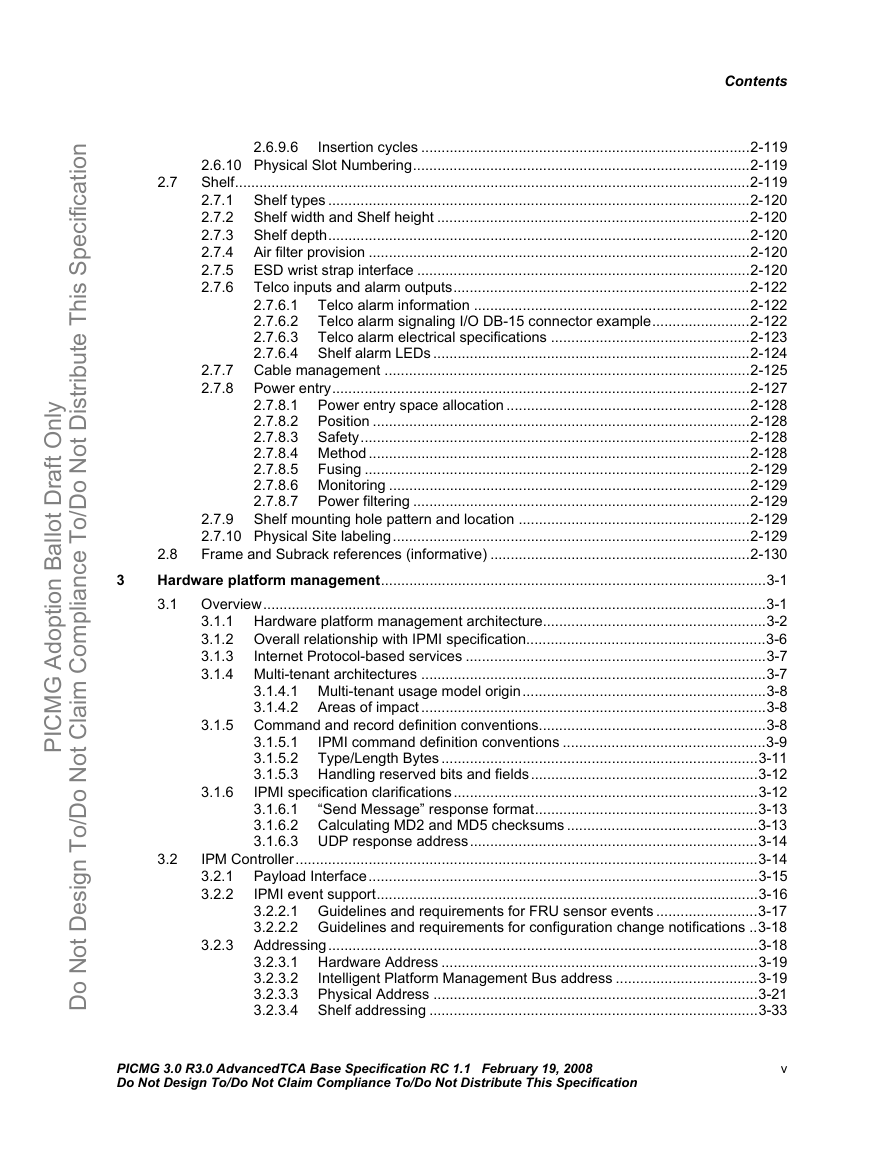
Contents Contents 1 1.2 2 2.2 Introduction and objectives.......................................................................................................1-1 Objective............................................................................................................................1-2 1.1 Special word usage ..............................................................................................1-2 1.1.1 1.1.2 Statement of compliance ......................................................................................1-3 Reference documents........................................................................................................1-4 1.2.1 Reference specifications.......................................................................................1-4 1.2.2 Contact information for reference organizations...................................................1-6 1.2.3 Environment and regulatory documents ...............................................................1-7 Name and logo usage........................................................................................................1-7 1.3 Signal naming conventions................................................................................................1-8 1.4 Intellectual Property ...........................................................................................................1-8 1.5 Special terms and acronyms ...........................................................................................1-10 1.6 Dimensions ......................................................................................................................1-21 1.7 Mechanical ..................................................................................................................................2-1 2.1 Mechanical overview .........................................................................................................2-1 2.1.1 Tolerances ............................................................................................................2-4 2.1.2 Standard orientation .............................................................................................2-4 2.1.3 Horizontal orientation............................................................................................2-4 2.1.4 Drawing symbols ..................................................................................................2-4 2.1.5 Keepout zones......................................................................................................2-7 Front Board assembly........................................................................................................2-7 Front Board PCB dimensions ...............................................................................2-7 2.2.1 Front Board PCB thickness ................................................................................2-11 2.2.2 2.2.3 Front Board pitch and offset ...............................................................................2-11 2.2.4 Component height ..............................................................................................2-13 Front Board warpage ..........................................................................2-15 2.2.4.1 2.2.4.2 Front Board stiffening..........................................................................2-15 ESD Strip ............................................................................................................2-15 Front Board covers .............................................................................................2-17 Front Board Face Plate.......................................................................................2-21 Front Board Face Plate Handles.........................................................2-25 2.2.7.1 Front Board Face Plate Alignment and Safety Ground Pin ................2-28 2.2.7.2 2.2.7.3 Front Board Face Plate retention screws............................................2-29 2.2.7.4 Front Board Filler Panels ....................................................................2-29 Front Board Face Plate LEDs.............................................................................2-30 2.2.8.1 General status LEDs...........................................................................2-32 2.2.8.2 Application specific LEDs....................................................................2-34 Front Board Face Plate labels ............................................................................2-34 AdvancedTCA® logo label and vendor logo label ..............................2-34 2.2.9.1 2.2.9.2 Barcode label ......................................................................................2-34 2.2.10 Test dimensions..................................................................................................2-35 RTM assembly.................................................................................................................2-36 2.3.1 RTM direct mate to Front Board .........................................................................2-37 2.3.1.1 RTM PCB dimensions.........................................................................2-37 2.3.1.2 RTM PCB thickness............................................................................2-40 2.3.1.3 RTM pitch and offset...........................................................................2-40 2.3.1.4 RTM component height.......................................................................2-40 2.3.1.5 RTM ESD Strip ...................................................................................2-41 2.2.5 2.2.6 2.2.7 2.2.8 2.2.9 2.3 PICMG 3.0 R3.0 AdvancedTCA Base Specification RC 1.1 February 19, 2008 Do Not Design To/Do Not Claim Compliance To/Do Not Distribute This Specification iii PICMG Adoption Ballot Draft OnlyDo Not Design To/Do Not Claim Compliance To/Do Not Distribute This Specification
Contents 2.4 2.5 2.6 2.4.2 2.4.3 2.4.4 2.3.1.6 RTM Covers........................................................................................2-43 2.3.1.7 RTM Face Plate..................................................................................2-44 2.3.1.8 RTM Face Plate LEDs ........................................................................2-50 2.3.1.9 RTM Face Plate labels........................................................................2-53 2.3.1.10 RTM airflow requirements and direction .............................................2-54 2.3.1.11 Zone 3 airflow seal..............................................................................2-54 2.3.1.12 RTM Zone 3 keying.............................................................................2-57 Zone 3 Cable Bulkhead ......................................................................................2-58 2.3.2 2.3.3 RTM connection to Zone 3 midplane..................................................................2-60 Zone 1, 2, and 3 connectors............................................................................................2-63 Zone 1 Connector...............................................................................................2-64 2.4.1 2.4.1.1 Description..........................................................................................2-64 2.4.1.2 -48 VDC power circuit definitions........................................................2-68 2.4.1.3 Metallic Test Bus circuits ....................................................................2-68 2.4.1.4 Ringing Generator Bus circuit.............................................................2-70 2.4.1.5 Hardware platform management circuit definitions.............................2-71 Zone 2 Connectors .............................................................................................2-72 2.4.2.1 General description of Zone 2 Connectors .........................................2-73 Pin numbering.....................................................................................2-73 2.4.2.2 2.4.2.3 Sequential mating ...............................................................................2-74 Zone 3 Connectors .............................................................................................2-74 2.4.3.1 General description.............................................................................2-74 Zone 3 Connector envelope................................................................2-75 2.4.3.2 Insertion force .....................................................................................2-77 2.4.3.3 2.4.3.4 Alignment allowances/gatherability.....................................................2-77 Front Board and RTM alignment/keying .............................................................2-78 Alignment overview.............................................................................2-78 2.4.4.1 Keying overview..................................................................................2-78 2.4.4.2 2.4.4.3 Zone 1 and Zone 2 keying/alignment..................................................2-80 2.4.4.4 RTM alignment....................................................................................2-84 Zone 3 alignment and keying..............................................................2-87 2.4.4.5 Backplanes ......................................................................................................................2-92 2.5.1 Description..........................................................................................................2-93 2.5.2 Connector locations............................................................................................2-94 Subrack............................................................................................................................2-96 Subrack features.................................................................................................2-97 2.6.1 Backplane support bar......................................................................................2-104 2.6.2 2.6.3 Subrack interface requirements for Front Boards.............................................2-106 2.6.4 Guide Rail requirements...................................................................................2-109 Front Board and RTM Guide Rail requirements ...............................2-109 2.6.4.1 Logical Slot identification ..................................................................2-112 2.6.4.2 2.6.4.3 ESD Clip position in the Guide Rails.................................................2-113 2.6.5 Face Plate Alignment and Safety Ground Pin ..................................................2-114 2.6.6 Retention screw receptacle ..............................................................................2-115 Subrack EMC Gasketing requirements ............................................................2-115 2.6.7 Subrack load carrying capability.......................................................................2-117 2.6.8 2.6.9 Subrack integrity tests ......................................................................................2-118 Subrack shock and vibration performance........................................2-118 2.6.9.1 Earthquake performance ..................................................................2-118 2.6.9.2 Flammability......................................................................................2-118 2.6.9.3 2.6.9.4 Shelf climatic test..............................................................................2-118 Shelf atmosphere test.......................................................................2-119 2.6.9.5 iv PICMG 3.0 R3.0 AdvancedTCA Base Specification RC 1.1 February 19, 2008 Do Not Design To/Do Not Claim Compliance To/Do Not Distribute This Specification PICMG Adoption Ballot Draft OnlyDo Not Design To/Do Not Claim Compliance To/Do Not Distribute This Specification
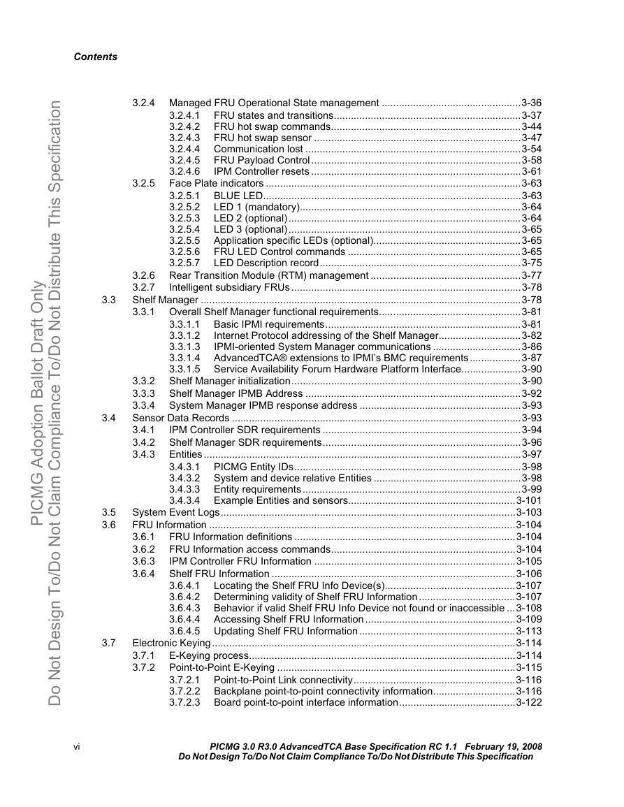
Contents 2.7 3 2.6.9.6 Insertion cycles .................................................................................2-119 2.6.10 Physical Slot Numbering...................................................................................2-119 Shelf...............................................................................................................................2-119 Shelf types ........................................................................................................2-120 2.7.1 Shelf width and Shelf height .............................................................................2-120 2.7.2 Shelf depth........................................................................................................2-120 2.7.3 Air filter provision ..............................................................................................2-120 2.7.4 2.7.5 ESD wrist strap interface ..................................................................................2-120 Telco inputs and alarm outputs.........................................................................2-122 2.7.6 Telco alarm information ....................................................................2-122 2.7.6.1 Telco alarm signaling I/O DB-15 connector example........................2-122 2.7.6.2 2.7.6.3 Telco alarm electrical specifications .................................................2-123 Shelf alarm LEDs ..............................................................................2-124 2.7.6.4 2.7.7 Cable management ..........................................................................................2-125 Power entry.......................................................................................................2-127 2.7.8 2.7.8.1 Power entry space allocation ............................................................2-128 Position .............................................................................................2-128 2.7.8.2 2.7.8.3 Safety................................................................................................2-128 2.7.8.4 Method ..............................................................................................2-128 2.7.8.5 Fusing ...............................................................................................2-129 2.7.8.6 Monitoring .........................................................................................2-129 2.7.8.7 Power filtering ...................................................................................2-129 2.7.9 Shelf mounting hole pattern and location .........................................................2-129 2.7.10 Physical Site labeling........................................................................................2-129 2.8 Frame and Subrack references (informative) ................................................................2-130 Hardware platform management...............................................................................................3-1 Overview............................................................................................................................3-1 3.1 3.1.1 Hardware platform management architecture.......................................................3-2 3.1.2 Overall relationship with IPMI specification...........................................................3-6 3.1.3 Internet Protocol-based services ..........................................................................3-7 3.1.4 Multi-tenant architectures .....................................................................................3-7 3.1.4.1 Multi-tenant usage model origin............................................................3-8 3.1.4.2 Areas of impact .....................................................................................3-8 3.1.5 Command and record definition conventions........................................................3-8 IPMI command definition conventions ..................................................3-9 3.1.5.1 3.1.5.2 Type/Length Bytes ..............................................................................3-11 3.1.5.3 Handling reserved bits and fields........................................................3-12 IPMI specification clarifications...........................................................................3-12 3.1.6.1 “Send Message” response format.......................................................3-13 3.1.6.2 Calculating MD2 and MD5 checksums ...............................................3-13 3.1.6.3 UDP response address.......................................................................3-14 IPM Controller..................................................................................................................3-14 Payload Interface................................................................................................3-15 3.2.1 IPMI event support..............................................................................................3-16 3.2.2 3.2.2.1 Guidelines and requirements for FRU sensor events .........................3-17 3.2.2.2 Guidelines and requirements for configuration change notifications ..3-18 Addressing..........................................................................................................3-18 3.2.3.1 Hardware Address ..............................................................................3-19 Intelligent Platform Management Bus address ...................................3-19 3.2.3.2 3.2.3.3 Physical Address ................................................................................3-21 Shelf addressing .................................................................................3-33 3.2.3.4 3.2 3.1.6 3.2.3 PICMG 3.0 R3.0 AdvancedTCA Base Specification RC 1.1 February 19, 2008 Do Not Design To/Do Not Claim Compliance To/Do Not Distribute This Specification v PICMG Adoption Ballot Draft OnlyDo Not Design To/Do Not Claim Compliance To/Do Not Distribute This Specification
Contents 3.2.5 3.2.4 Managed FRU Operational State management .................................................3-36 3.2.4.1 FRU states and transitions..................................................................3-37 3.2.4.2 FRU hot swap commands...................................................................3-44 3.2.4.3 FRU hot swap sensor .........................................................................3-47 3.2.4.4 Communication lost ............................................................................3-54 FRU Payload Control..........................................................................3-58 3.2.4.5 3.2.4.6 IPM Controller resets ..........................................................................3-61 Face Plate indicators ..........................................................................................3-63 BLUE LED...........................................................................................3-63 3.2.5.1 LED 1 (mandatory)..............................................................................3-64 3.2.5.2 LED 2 (optional)..................................................................................3-64 3.2.5.3 LED 3 (optional)..................................................................................3-65 3.2.5.4 3.2.5.5 Application specific LEDs (optional)....................................................3-65 FRU LED Control commands .............................................................3-65 3.2.5.6 3.2.5.7 LED Description record.......................................................................3-75 3.2.6 Rear Transition Module (RTM) management .....................................................3-77 3.2.7 Intelligent subsidiary FRUs .................................................................................3-78 Shelf Manager .................................................................................................................3-78 3.3.1 Overall Shelf Manager functional requirements..................................................3-81 Basic IPMI requirements.....................................................................3-81 3.3.1.1 Internet Protocol addressing of the Shelf Manager.............................3-82 3.3.1.2 IPMI-oriented System Manager communications ...............................3-86 3.3.1.3 AdvancedTCA® extensions to IPMI’s BMC requirements..................3-87 3.3.1.4 3.3.1.5 Service Availability Forum Hardware Platform Interface.....................3-90 Shelf Manager initialization.................................................................................3-90 3.3.2 Shelf Manager IPMB Address ............................................................................3-92 3.3.3 3.3.4 System Manager IPMB response address .........................................................3-93 Sensor Data Records ......................................................................................................3-93 IPM Controller SDR requirements ......................................................................3-94 3.4.1 3.4.2 Shelf Manager SDR requirements......................................................................3-96 Entities................................................................................................................3-97 3.4.3 PICMG Entity IDs................................................................................3-98 3.4.3.1 System and device relative Entities ....................................................3-98 3.4.3.2 3.4.3.3 Entity requirements.............................................................................3-99 Example Entities and sensors...........................................................3-101 3.4.3.4 System Event Logs........................................................................................................3-103 FRU Information ............................................................................................................3-104 3.6.1 FRU Information definitions ..............................................................................3-104 FRU Information access commands.................................................................3-104 3.6.2 IPM Controller FRU Information .......................................................................3-105 3.6.3 Shelf FRU Information ......................................................................................3-106 3.6.4 3.6.4.1 Locating the Shelf FRU Info Device(s)..............................................3-107 3.6.4.2 Determining validity of Shelf FRU Information..................................3-107 Behavior if valid Shelf FRU Info Device not found or inaccessible ...3-108 3.6.4.3 3.6.4.4 Accessing Shelf FRU Information.....................................................3-109 3.6.4.5 Updating Shelf FRU Information.......................................................3-113 Electronic Keying...........................................................................................................3-114 E-Keying process..............................................................................................3-114 3.7.1 Point-to-Point E-Keying ....................................................................................3-115 3.7.2 Point-to-Point Link connectivity.........................................................3-116 3.7.2.1 3.7.2.2 Backplane point-to-point connectivity information.............................3-116 Board point-to-point interface information.........................................3-122 3.7.2.3 3.3 3.4 3.5 3.6 3.7 vi PICMG 3.0 R3.0 AdvancedTCA Base Specification RC 1.1 February 19, 2008 Do Not Design To/Do Not Claim Compliance To/Do Not Distribute This Specification PICMG Adoption Ballot Draft OnlyDo Not Design To/Do Not Claim Compliance To/Do Not Distribute This Specification
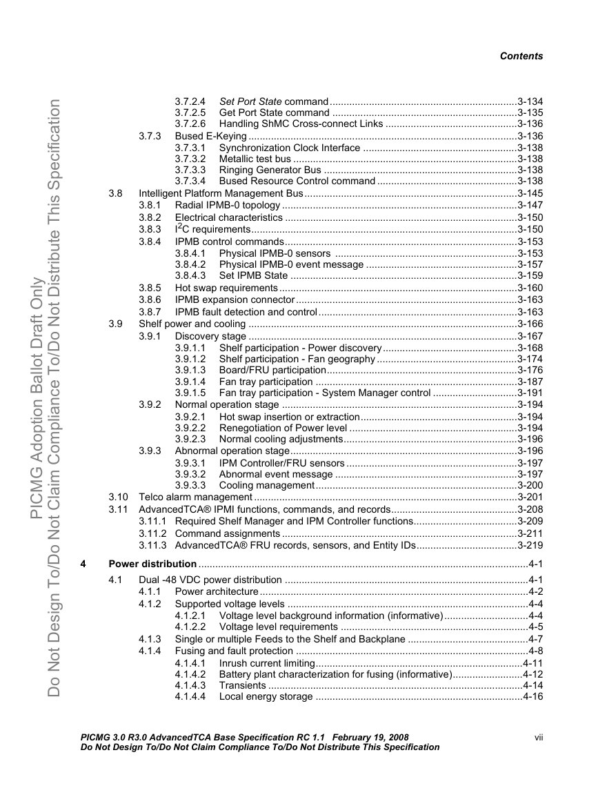
Contents 3.7.3 3.9.3 3.8 3.9 3.9.1.1 3.9.1.2 3.9.1.3 3.9.1.4 3.9.1.5 3.7.2.4 Set Port State command...................................................................3-134 3.7.2.5 Get Port State command ..................................................................3-135 3.7.2.6 Handling ShMC Cross-connect Links ...............................................3-136 Bused E-Keying ................................................................................................3-136 3.7.3.1 Synchronization Clock Interface .......................................................3-138 3.7.3.2 Metallic test bus ................................................................................3-138 3.7.3.3 Ringing Generator Bus .....................................................................3-138 3.7.3.4 Bused Resource Control command ..................................................3-138 Intelligent Platform Management Bus............................................................................3-145 3.8.1 Radial IPMB-0 topology ....................................................................................3-147 Electrical characteristics ...................................................................................3-150 3.8.2 I2C requirements...............................................................................................3-150 3.8.3 IPMB control commands...................................................................................3-153 3.8.4 Physical IPMB-0 sensors .................................................................3-153 3.8.4.1 Physical IPMB-0 event message ......................................................3-157 3.8.4.2 3.8.4.3 Set IPMB State .................................................................................3-159 3.8.5 Hot swap requirements.....................................................................................3-160 IPMB expansion connector...............................................................................3-163 3.8.6 3.8.7 IPMB fault detection and control.......................................................................3-163 Shelf power and cooling ................................................................................................3-166 3.9.1 Discovery stage ................................................................................................3-167 Shelf participation - Power discovery................................................3-168 Shelf participation - Fan geography ..................................................3-174 Board/FRU participation....................................................................3-176 Fan tray participation ........................................................................3-187 Fan tray participation - System Manager control ..............................3-191 3.9.2 Normal operation stage ....................................................................................3-194 3.9.2.1 Hot swap insertion or extraction........................................................3-194 3.9.2.2 Renegotiation of Power level ............................................................3-194 3.9.2.3 Normal cooling adjustments..............................................................3-196 Abnormal operation stage.................................................................................3-196 IPM Controller/FRU sensors .............................................................3-197 3.9.3.1 3.9.3.2 Abnormal event message .................................................................3-197 3.9.3.3 Cooling management........................................................................3-200 3.10 Telco alarm management ..............................................................................................3-201 3.11 AdvancedTCA® IPMI functions, commands, and records.............................................3-208 3.11.1 Required Shelf Manager and IPM Controller functions.....................................3-209 3.11.2 Command assignments ....................................................................................3-211 3.11.3 AdvancedTCA® FRU records, sensors, and Entity IDs....................................3-219 Power distribution ......................................................................................................................4-1 4.1 Dual -48 VDC power distribution .......................................................................................4-1 Power architecture................................................................................................4-2 4.1.1 Supported voltage levels ......................................................................................4-4 4.1.2 Voltage level background information (informative)..............................4-4 4.1.2.1 4.1.2.2 Voltage level requirements ...................................................................4-5 Single or multiple Feeds to the Shelf and Backplane ...........................................4-7 Fusing and fault protection ...................................................................................4-8 Inrush current limiting..........................................................................4-11 4.1.4.1 Battery plant characterization for fusing (informative).........................4-12 4.1.4.2 4.1.4.3 Transients ...........................................................................................4-14 Local energy storage ..........................................................................4-16 4.1.4.4 4.1.3 4.1.4 4 PICMG 3.0 R3.0 AdvancedTCA Base Specification RC 1.1 February 19, 2008 Do Not Design To/Do Not Claim Compliance To/Do Not Distribute This Specification vii PICMG Adoption Ballot Draft OnlyDo Not Design To/Do Not Claim Compliance To/Do Not Distribute This Specification
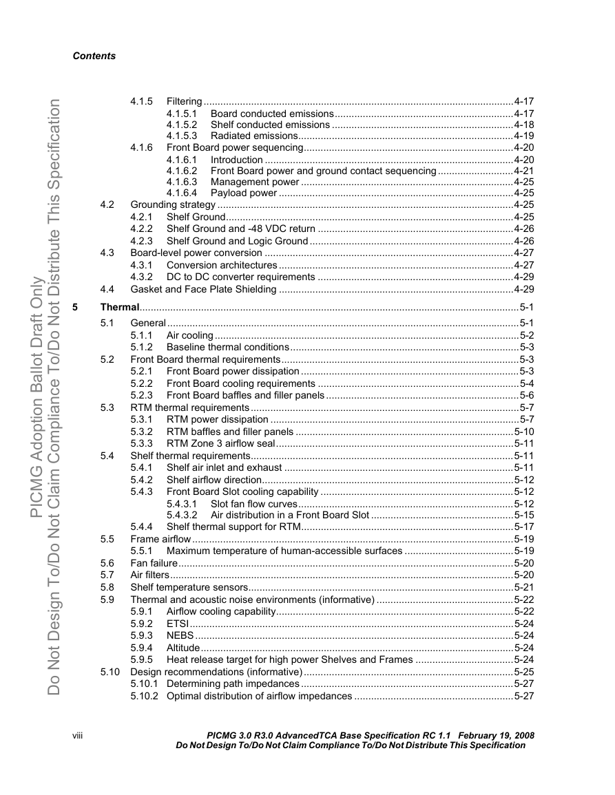
Contents 5 4.2 4.3 5.2 5.5 4.1.5 4.1.6 Filtering...............................................................................................................4-17 Board conducted emissions................................................................4-17 4.1.5.1 4.1.5.2 Shelf conducted emissions .................................................................4-18 4.1.5.3 Radiated emissions.............................................................................4-19 Front Board power sequencing...........................................................................4-20 Introduction .........................................................................................4-20 4.1.6.1 4.1.6.2 Front Board power and ground contact sequencing...........................4-21 4.1.6.3 Management power ............................................................................4-25 Payload power ....................................................................................4-25 4.1.6.4 Grounding strategy ..........................................................................................................4-25 Shelf Ground.......................................................................................................4-25 4.2.1 4.2.2 Shelf Ground and -48 VDC return ......................................................................4-26 4.2.3 Shelf Ground and Logic Ground.........................................................................4-26 Board-level power conversion .........................................................................................4-27 4.3.1 Conversion architectures ....................................................................................4-27 4.3.2 DC to DC converter requirements ......................................................................4-29 4.4 Gasket and Face Plate Shielding ....................................................................................4-29 Thermal........................................................................................................................................5-1 General..............................................................................................................................5-1 5.1 5.1.1 Air cooling.............................................................................................................5-2 5.1.2 Baseline thermal conditions..................................................................................5-3 Front Board thermal requirements.....................................................................................5-3 Front Board power dissipation..............................................................................5-3 5.2.1 5.2.2 Front Board cooling requirements ........................................................................5-4 5.2.3 Front Board baffles and filler panels.....................................................................5-6 RTM thermal requirements................................................................................................5-7 5.3.1 RTM power dissipation .........................................................................................5-7 5.3.2 RTM baffles and filler panels ..............................................................................5-10 5.3.3 RTM Zone 3 airflow seal.....................................................................................5-11 Shelf thermal requirements..............................................................................................5-11 Shelf air inlet and exhaust ..................................................................................5-11 5.4.1 5.4.2 Shelf airflow direction..........................................................................................5-12 Front Board Slot cooling capability .....................................................................5-12 5.4.3 Slot fan flow curves.............................................................................5-12 5.4.3.1 5.4.3.2 Air distribution in a Front Board Slot ...................................................5-15 Shelf thermal support for RTM............................................................................5-17 5.4.4 Frame airflow...................................................................................................................5-19 5.5.1 Maximum temperature of human-accessible surfaces .......................................5-19 Fan failure........................................................................................................................5-20 Air filters...........................................................................................................................5-20 Shelf temperature sensors...............................................................................................5-21 Thermal and acoustic noise environments (informative) .................................................5-22 Airflow cooling capability.....................................................................................5-22 5.9.1 5.9.2 ETSI....................................................................................................................5-24 5.9.3 NEBS..................................................................................................................5-24 5.9.4 Altitude................................................................................................................5-24 5.9.5 Heat release target for high power Shelves and Frames ...................................5-24 5.10 Design recommendations (informative)...........................................................................5-25 5.10.1 Determining path impedances............................................................................5-27 5.10.2 Optimal distribution of airflow impedances .........................................................5-27 5.6 5.7 5.8 5.9 5.3 5.4 viii PICMG 3.0 R3.0 AdvancedTCA Base Specification RC 1.1 February 19, 2008 Do Not Design To/Do Not Claim Compliance To/Do Not Distribute This Specification PICMG Adoption Ballot Draft OnlyDo Not Design To/Do Not Claim Compliance To/Do Not Distribute This Specification
分享到:
收藏