QuantaMesh T3040-LY3
Network Switch
(Layer 2/3 Managed 10GBT Switch)
Installation Guide
�
Contents
Chapter 1: Safety and Regulatory Information .............................1
1.1 Copyright ...................................................................................2
1.2 About the Manual ......................................................................2
1.3 Intended Application Uses .........................................................2
1.4 Safety Information .....................................................................2
1.4.1 Switch Safety Information ...............................................2
1.4.2 Installation Assembly Safety Instructions .......................4
1.4.3 Site Selection ..................................................................4
1.4.4 Equipment Handling Practices ........................................5
1.4.5 Power and Electrical Warnings .......................................5
1.4.6 Power Cord Warnings .....................................................6
1.4.7 System Access Warnings ...............................................6
1.4.8 Rack Mount Warnings ....................................................7
1.4.9 Other Hazards ................................................................8
1.5 Regulatory and Compliance Information ...................................9
1.5.1 Electromagnetic Compatibility Notices ...........................9
1.5.2 Product Regulatory Compliance Markings ...................11
Chapter 2: Introduction .................................................................12
2.1 Front Panel ..............................................................................13
2.1.1 LED Description ............................................................13
2.2 Rear Panel ...............................................................................14
2.3 Package Contents ...................................................................15
Chapter 3: Hardware Installation .................................................... 16
3.1 Unpack the Hardware ..............................................................17
3.2 Install the Switch ......................................................................17
3.2.1 Select the Location .......................................................17
3.2.2 Install the Switch ...........................................................18
3.3 Connect to Power ....................................................................20
3.4 Check the Installation ..............................................................20
3.5 Connect Equipment .................................................................20
3.5.1 10GBASE-T Port ..........................................................20
3.5.2 SFP+ Port .....................................................................21
3.6 Connect to Console Port .........................................................22
3.7 Connect to Management Port ..................................................23
3.8 Connect to USB Port ...............................................................24
Chapter 4: Initial Configuration ...................................................... 25
4.1 Initial Configuration Process ....................................................26
4.2 Configure the IP Address ........................................................26
4.2.1 Set IP Address Manually ..............................................26
4.2.2 Obtain IP Address by DHCP .........................................27
4.3 Manage the Switch ..................................................................28
4.3.1 CLI Management ..........................................................28
4.3.2 SNMP Management .....................................................28
�
Contents
4.4 Upgrade the Firmware .............................................................29
4.4.1 Initialization Stage .........................................................29
4.4.2 Upgrade the Firmware Image File ................................30
4.5 Manually Install Vendor OS .....................................................31
Chapter 5: Troubleshooting .........................................................33
5.1 Troubleshooting .......................................................................34
5.2 Replace the Power Supply Unit ...............................................34
5.2.1 Remove the Power Supply Unit ....................................36
5.2.2 Replace the Power Supply Unit ....................................36
5.3 Customer Support ...................................................................36
H
S
I
L
G
N
E
iii
�
List of Figures
Figure 2-1: Front Panel View ...........................................................13
Figure 2-2: 10GBASE-T and SFP+ Port LEDs ................................13
Figure 2-3: Console and Management Port LEDs...........................14
Figure 2-4: Rear Panel View ...........................................................14
Figure 3-1: Attach Footpads ............................................................18
Figure 3-2: Attach Brackets .............................................................19
Figure 3-3: Install Switch on Rack ...................................................19
Figure 3-4: 10GBASE-T Port Numbering ........................................20
Figure 3-5: Connect 10GBASE-T Module .......................................21
Figure 3-6: SFP+ Port Numbering ...................................................21
Figure 3-7: Connect SFP+ Module ..................................................22
Figure 3-8: Connect to Console Port ...............................................23
Figure 3-9: Connect to Management Port .......................................23
Figure 3-10: Connect to USB Port ...................................................24
Figure 4-1: Boot Up Console Screen...............................................26
Figure 4-2: Set Service Port IP Screen ...........................................27
Figure 4-3: Set Service Port IP Screen ...........................................29
Figure 4-4: Example of TFTP Server Screen ..................................30
Figure 4-5: Backup Image Screen Sample......................................30
Figure 4-6: Set Boot Image Success Screen Sample .....................30
Figure 4-7: Enter ONIE Linux Shell Screen .....................................31
Figure 4-8: Stop ONIE Service Discovery Screen ...........................31
Figure 4-9: Set Your Switch Box IP Address Screen ......................32
Figure 4-10: Verify IP Address Setting Screen ................................32
Figure 5-1: Access PSU Info on Web Utility ....................................35
Figure 5-2: Remove Power Supply Unit ..........................................36
�
List of Tables
Table 1-1: Manual Conventions Icon .................................................2
Table 1-2: Product Regulatory Compliance Markings .....................11
Table 2-1: 10GBASE-T and SFP+ Port LEDs .................................13
Table 2-2: Console and Management Port LEDs ............................14
Table 5-1: Troubleshooting Tips ......................................................34
�
Chapter 1: Safety and Regulatory Information
This chapter contains important information on safety and
regulatory, as well as conventions used in this installation guide.
Read this guide before installing and operating the system.
�
Safety and Regulatory Information
Copyright
1.1
All specifications and figures are subject to change without prior notice. Actual products may look
different from the photos.
All trademarks and logos mentioned in this guide are the properties of their respective holders.
Copyright © 2017 Quanta Computer Inc. All rights reserved.
E
N
G
L
I
S
H
About the Manual
1.2
This installation guide is meant for network administrators with inept knowledge in network
management.
To avoid personal injury or property damage, before you begin installing the product, read, observe,
and adhere to all the following safety instructions and information.
The following symbols are used throughout the guide to highlight important information and may be
marked on the product and / or the product packaging.
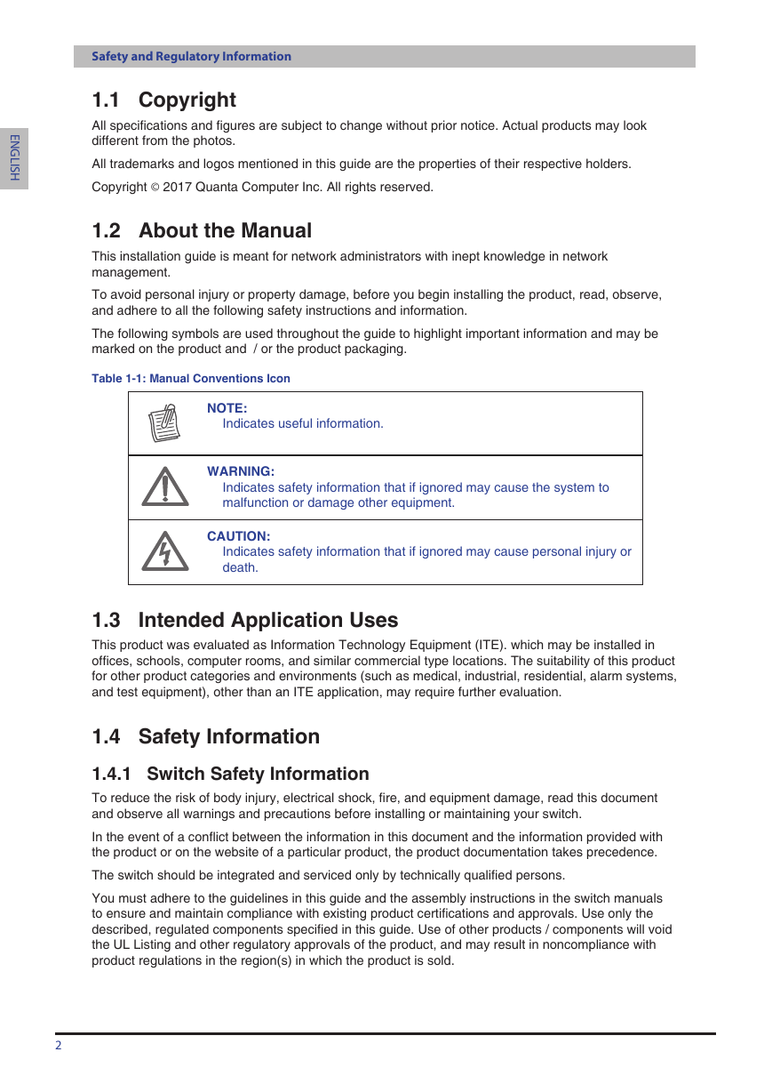
Table 1-1:
Manual Conventions Icon
NOTE:
Indicates useful information.
WARNING:
Indicates safety information that if ignored may cause the system to
malfunction or damage other equipment.
CAUTION:
Indicates safety information that if ignored may cause personal injury or
death.
Intended Application Uses
1.3
This product was evaluated as Information Technology Equipment (ITE). which may be installed in
offices, schools, computer rooms, and similar commercial type locations. The suitability of this product
for other product categories and environments (such as medical, industrial, residential, alarm systems,
and test equipment), other than an ITE application, may require further evaluation.
1.4
Safety Information
Switch Safety Information
1.4.1
To reduce the risk of body injury, electrical shock, fire, and equipment damage, read this document
and observe all warnings and precautions before installing or maintaining your switch.
In the event of a conflict between the information in this document and the information provided with
the product or on the website of a particular product, the product documentation takes precedence.
The switch should be integrated and serviced only by technically qualified persons.
You must adhere to the guidelines in this guide and the assembly instructions in the switch manuals
to ensure and maintain compliance with existing product certifications and approvals. Use only the
described, regulated components specified in this guide. Use of other products / components will void
the UL Listing and other regulatory approvals of the product, and may result in noncompliance with
product regulations in the region(s) in which the product is sold.
2
�
Safety and Regulatory Information
Follow the safety guidelines below to ensure personal safety and protect the system and the working
environment from potential damage.
CAUTION:
The power supplies in the system may produce high voltages and
energy hazards which can cause bodily harm. Do not remove the covers
and access any of the components inside the system.
H
S
I
L
G
N
E
CAUTION:
To reduce the risk of electrical shock, disconnect all power supply
cables before servicing the system.
CAUTION:
Do not use the mounted equipment as a shelf or a work space.
Restricted access location: The switch is intended for installation only
in a Server Room or Computer Room where both these conditions apply:
•
access can only be gained by SERVICE PERSONS or by USERS who
have been instructed about the reasons for the restricitons applied to
the location and about any precautions that shall be taken; and
access is through the use of a TOOL or lock and key, or other means
of security, and is controlled by the authority responsible for the
location.
•
WARNING:
When a power supply needs replacement, replace the power
supply only with the same or equivalent type recommended by the
manufacturer. Replacing with an incorrect power supply may cause
explosion.
•
•
•
•
•
•
•
•
•
•
•
Observe and follow service markings. Do not service the product yourself. Components inside
the system should only be serviced by trained service technician.
If any of the following conditions occur, unplug the equipment from the electrical outlet and
replace the part or contact a trained service technician:
•
•
•
•
The power cable, extension cable, or plug is damaged
The equipment has been exposed to water
The equipment has been dropped or damaged
The equipment does not operate correctly when you follow the operating instructions
Do not spill food or liquid on the equipment.
Never operate the equipment in a wet environment.
Do not push any objects into the opening of the equipment. Doing so may short internal
components and cause fire or electric shock.
Use the system only with approved equipment.
Allow the product to cool before removing any peripherals.
Operate the equipment only from the type of external power source indicated on the electrical
ratings label. If you are unsure of the type of power source required, consult your local power
company.
Use only approved power cable(s).
To help prevent electric shock, plug the system and peripheral power cables into properly
grounded electrical outlets. Do not use adapter plugs or remove the grounding prong from
a cable. If you must use an extension cable, use an extension cable with properly grounded
plugs.
Observe extension cable and power strip ratings. Ensure that the total ampere rating of all
3
�





 2023年江西萍乡中考道德与法治真题及答案.doc
 2012年重庆南川中考生物真题及答案.doc
 2013年江西师范大学地理学综合及文艺理论基础考研真题.doc
 2020年四川甘孜小升初语文真题及答案I卷.doc
 2020年注册岩土工程师专业基础考试真题及答案.doc
 2023-2024学年福建省厦门市九年级上学期数学月考试题及答案.doc
 2021-2022学年辽宁省沈阳市大东区九年级上学期语文期末试题及答案.doc
 2022-2023学年北京东城区初三第一学期物理期末试卷及答案.doc
 2018上半年江西教师资格初中地理学科知识与教学能力真题及答案.doc
 2012年河北国家公务员申论考试真题及答案-省级.doc
 2020-2021学年江苏省扬州市江都区邵樊片九年级上学期数学第一次质量检测试题及答案.doc
 2022下半年黑龙江教师资格证中学综合素质真题及答案.doc