Quadrature Signals: Complex, But Not Complicated
by Richard Lyons
-1 operator, don't feel bad because you're in good
Introduction
Quadrature signals are based on the notion of complex numbers and perhaps no other topic
causes more heartache for newcomers to DSP than these numbers and their strange terminology
of j-operator, complex, imaginary, real, and orthogonal. If you're a little unsure of the physical
meaning of complex numbers and the j =
company. Why even Karl Gauss, one the world's greatest mathematicians, called the j-operator
the "shadow of shadows". Here we'll shine some light on that shadow so you'll never have to
call the Quadrature Signal Psychic Hotline for help.
Quadrature signal processing is used in many fields of science and engineering, and quadrature
signals are necessary to describe the processing and implementation that takes place in modern
digital communications systems. In this tutorial we'll review the fundamentals of complex
numbers and get comfortable with how they're used to represent quadrature signals. Next we
examine the notion of negative frequency as it relates to quadrature signal algebraic notation,
and learn to speak the language of quadrature processing. In addition, we'll use three-
dimensional time and frequency-domain plots to give some physical meaning to quadrature
signals. This tutorial concludes with a brief look at how a quadrature signal can be generated by
means of quadrature-sampling.
Why Care About Quadrature Signals?
Quadrature signal formats, also called complex signals, are used in many digital signal
processing applications such as:
These applications fall in the general category known as quadrature processing, and they
provide additional processing power through the coherent measurement of the phase of
sinusoidal signals.
A quadrature signal is a two-dimensional signal whose value at some instant in time can be
specified by a single complex number having two parts; what we call the real part and the
imaginary part. (The words real and imaginary, although traditional, are unfortunate because
their of meanings in our every day speech. Communications engineers use the terms in-phase
and quadrature phase. More on that later.) Let's review the mathematical notation of these
complex numbers.
- digital communications systems,
- radar systems,
- time difference of arrival processing in radio direction finding schemes
- coherent pulse measurement systems,
- antenna beamforming applications,
- single sideband modulators,
- etc.
Copyright © November 2008, Richard Lyons, All Rights Reserved
�
The Development and Notation of Complex Numbers
To establish our terminology, we define a real number to be those numbers we use in every day
life, like a voltage, a temperature on the Fahrenheit scale, or the balance of your checking
account. These one-dimensional numbers can be either positive or negative as depicted in
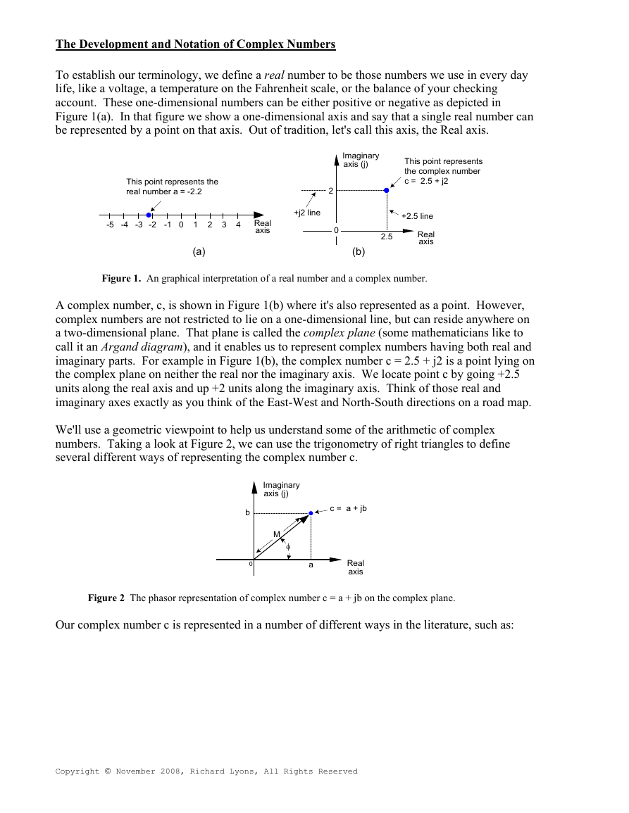
Figure 1(a). In that figure we show a one-dimensional axis and say that a single real number can
be represented by a point on that axis. Out of tradition, let's call this axis, the Real axis.
This point represents the
real number a = -2.2
-5 -4 -3
-2
-1
0
1
2
3
4
Real
axis
(a)
+j2 line
2
0
Imaginary
axis (j)
This point represents
the complex number
c = 2.5 + j2
+2.5 line
Real
axis
2.5
(b)
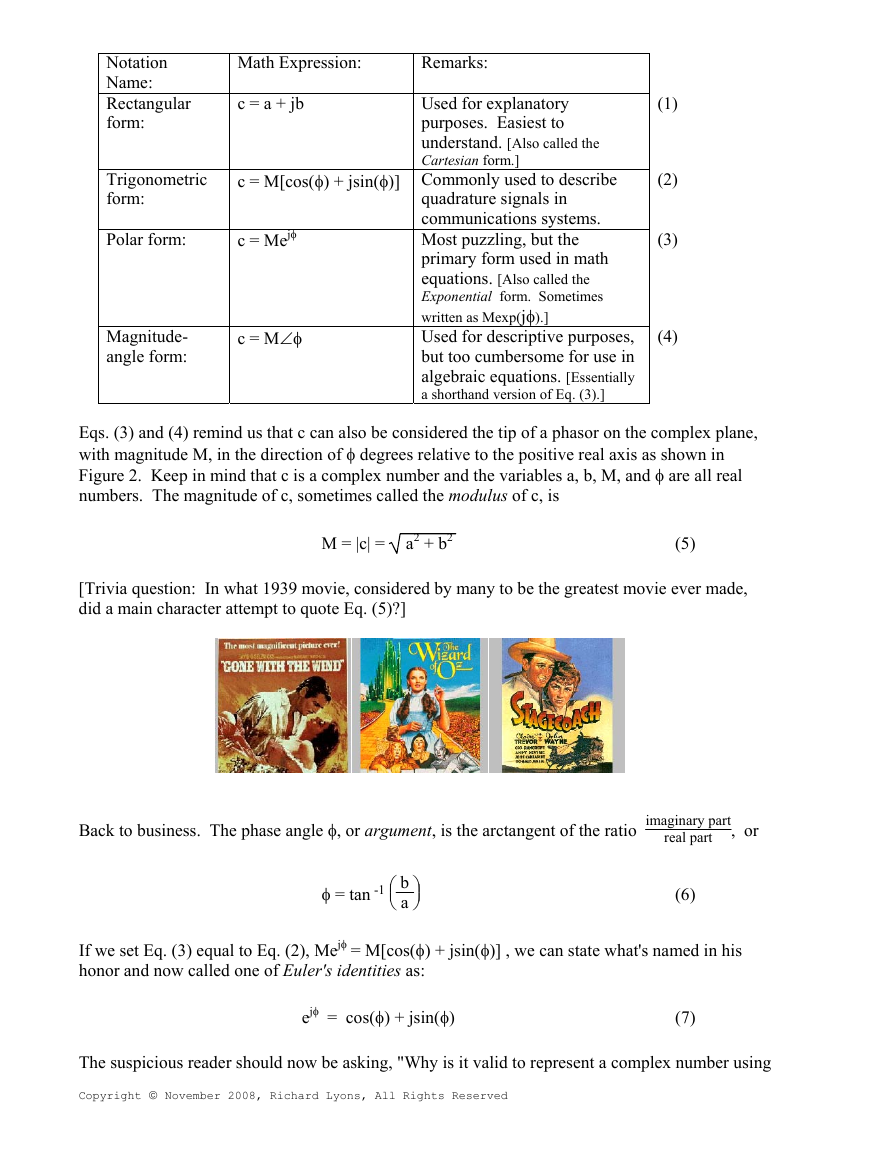
Figure 2 The phasor representation of complex number c = a + jb on the complex plane.
Our complex number c is represented in a number of different ways in the literature, such as:
Copyright © November 2008, Richard Lyons, All Rights Reserved
Figure 1. An graphical interpretation of a real number and a complex number.
A complex number, c, is shown in Figure 1(b) where it's also represented as a point. However,
complex numbers are not restricted to lie on a one-dimensional line, but can reside anywhere on
a two-dimensional plane. That plane is called the complex plane (some mathematicians like to
call it an Argand diagram), and it enables us to represent complex numbers having both real and
imaginary parts. For example in Figure 1(b), the complex number c = 2.5 + j2 is a point lying on
the complex plane on neither the real nor the imaginary axis. We locate point c by going +2.5
units along the real axis and up +2 units along the imaginary axis. Think of those real and
imaginary axes exactly as you think of the East-West and North-South directions on a road map.
We'll use a geometric viewpoint to help us understand some of the arithmetic of complex
numbers. Taking a look at Figure 2, we can use the trigonometry of right triangles to define
several different ways of representing the complex number c.
Imaginary
axis (j)
M
φ
b
0
c = a + jb
a
Real
axis
�
Notation
Name:
Rectangular
fo
rm:
Math Expression:
Remarks:
c = a + jb
Trigonometric
form:
Polar form:
c = M[cos(φ) + jsin(φ)]
c = Mejφ
Magnitude-
angle form:
c = M∠φ
(1)
(2)
(3)
(4)
s.
scribe
o called the
Used for explanatory
purposes. Easiest to
understand. [Als
Cartesian form.]
Commonly used to de
quadrature signals in
communications system
Most puzzling, but the
primary form used in ma
equations. [Also called the
Exponential form. Som
written as Mexp(jφ).]
Used for descriptive purposes,
but too cumbersome for use in
algebraic equations. [Essentia
lly
a shorthand version of Eq. (3).]
etimes
th
Eqs. (3) and (4) remind us that c can also be considered the tip of a phasor on the complex pla
with magnitude M, in the direction of φ degrees relative to the positive real axis as shown in
Figure 2. Keep in mind that c is a complex number and the variables
umbers. The magnitude of c, sometimes called the modulus of c, is
n
[Trivia question: In what 1939 movie, consider
id a main character attempt to quote Eq. (5)?]
d
ed by many to be the greatest movie ever made,
a, b, M, and φ are all real
a2 + b2
M = |c| =
(5)
ne,
Back to business. The phase angle φ, or argument, is the arctangent of the ratio
φ = tan -1
⎟⎞ b
⎠ a
⎜⎛
⎝
imaginary p
real part
art
, or
(6)
+ jsin(φ)] , we can state what's named in his
If we set Eq. (3) equal to Eq. (2), Mejφ = M[cos(φ)
onor and now called one of Euler's identities as:
h
The suspicious reader should now be asking, "Why is it valid to represent a complex number using
Copyright © November 2008, Richard Lyons, All Rights Reserved
ejφ = cos(φ) + jsin(φ)
(7)
�
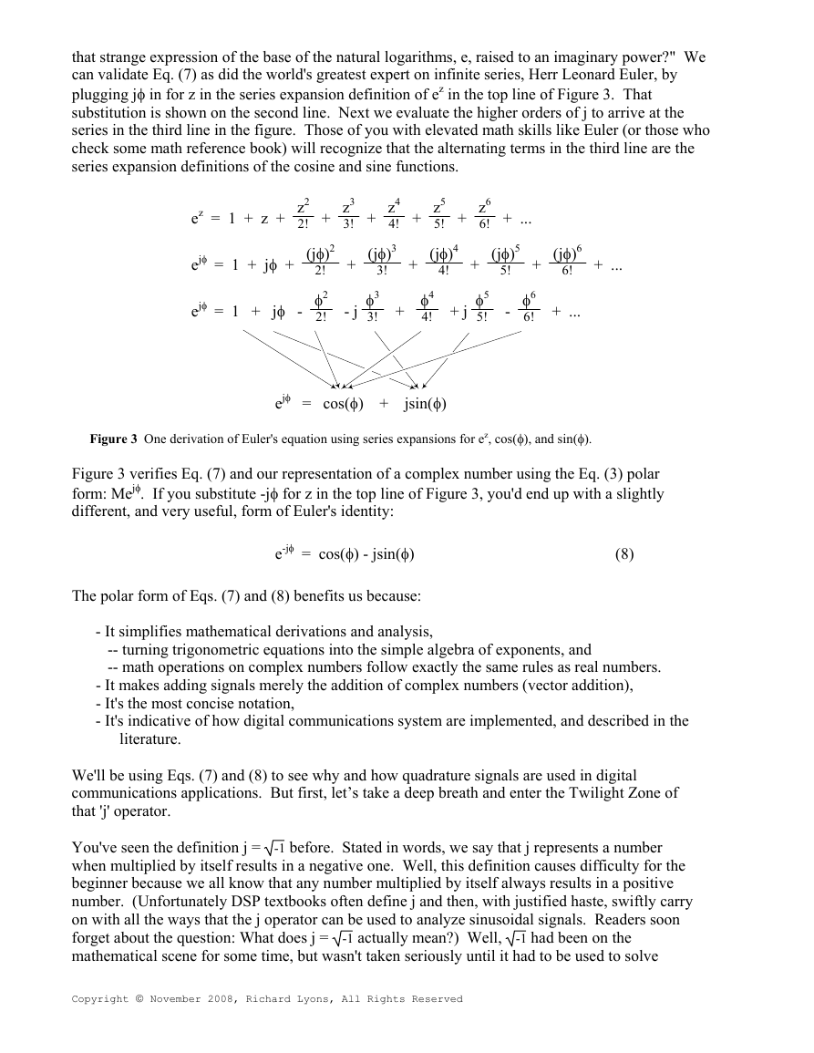
that strange expression of the base of the natural logarithms, e, raised to an imaginary power?"
can validate Eq. (7) as did the world's greatest expert on infinite series, Herr Leonard Euler,
by
plugging jφ in for z in the series expansion definition of ez in the top line of Figure 3. That
substitution is shown on the second line. Next we evaluate the higher orders of j to arrive at the
series in the third line in the figure. Those of you with elevated math skills like Euler (or those wh
check some math reference book) will recognize that the alter
nating terms in the third line are the
se
ries expansion definitions of the cosine and sine functions.
We
o
z2
z
e = 1 + z + 2!
z3
+ 3!
2
(jφ)
z5
z4
z6
+ 4! + 5! + 6!
3
(jφ)
4
(jφ)
+ ...
jφ
e = 1 + jφ +
+
2!
φ2
+
!
3
φ3
φ4
3! + 4!
+
4!
5
(jφ)
5!
+
6
(jφ)
6!
+ ...
φ5
+ j 5!
φ6
- 6!
+ ...
ejφ
= 1 + jφ - 2! - j
jφ
e = cos(φ) + jsin(φ)
Figure 3 One derivation of Euler's equation using series expansions for ez, cos(φ), and sin(φ).
Figure 3 verifies Eq. (7) and our representation of a complex number using the Eq. (3) polar
form: Mejφ. If you substitute -jφ for z in the top line
of Figure 3, you'd end up with a slightly
ifferent, and very useful, form of Euler's identity:
d
T
he polar form of Eqs. (7) and (8) benefits us because:
e-jφ = cos(φ) - jsin(φ)
(8)
-
It simplifies mathematical derivations and analysis,
-- turning trigonometric equations into the simple algebra of exponents, and
-- math operations on complex numbers follow exactly the same rules as real numbe
the addition of complex numbers (vector addition),
rs.
- It makes adding signals merely
- It's the most concise notation,
- It'
s indicative
literature.
of how digital communications system are implemented, and described in the
applications. But first, let’s take a deep breath and enter the Twilight Zone of
We'll be using Eqs. (7) and (8) to see why and how quadrature signals are used in digital
communications
at 'j' operator.
th
You've seen the definition j =
when multiplied by itself results in a negative one. Well, this definition causes difficulty for the
beginner because we all know that any number multiplied by itself always results in a positive
number. (Unfortunately DSP textbooks often define j and then, with justified haste, swiftly carry
on with all the ways that the j operator ca be used to analyze sinuso dal signals. Reader
s soon
forget about the question: What does j =
-1 had been on the
mathematical scene for some time, but wasn't taken seriously until it had to be used to solve
Copyright © November 2008, Richard Lyons, All Rights Reserved
-1 before. Stated in words, we say that j represents a number
n
-1 actually mean?) Well,
i
�
cubic equations in the sixteenth century. [1], [2] Mathematicians reluctantly began to accept the
abstract concept of
-1, without having to visualize it, because its mathematical properties were
c
onsistent with the arithmetic of normal real numbers.
It was Euler's equating complex numbers to real sines and cosines, and Gauss' brilliant
introduction of the complex plane, that finally legitimized the notion of
-1 to Europe's
mathematicians in the eighteenth century. Euler, going beyond the province of real numb
showed that complex numbers had a clean consistent relationship to the well-known real
trigonometric functions of sines and cosines. As Einstein showed the equivalence of mass an
energy, Euler showed the equivalence of real sines and cosines to complex numbers. Just as
modern-day physicists don’t know what an electron is but they understand its properties, we’ll
not worry about what 'j' is and be satisfied with understanding its behavior. For our purposes,
the j-operator means rotate a complex number by 90o counterclock
wise. (For you good folk in
th
e UK, counterclockwise means anti-clockwise.) Let's see why.
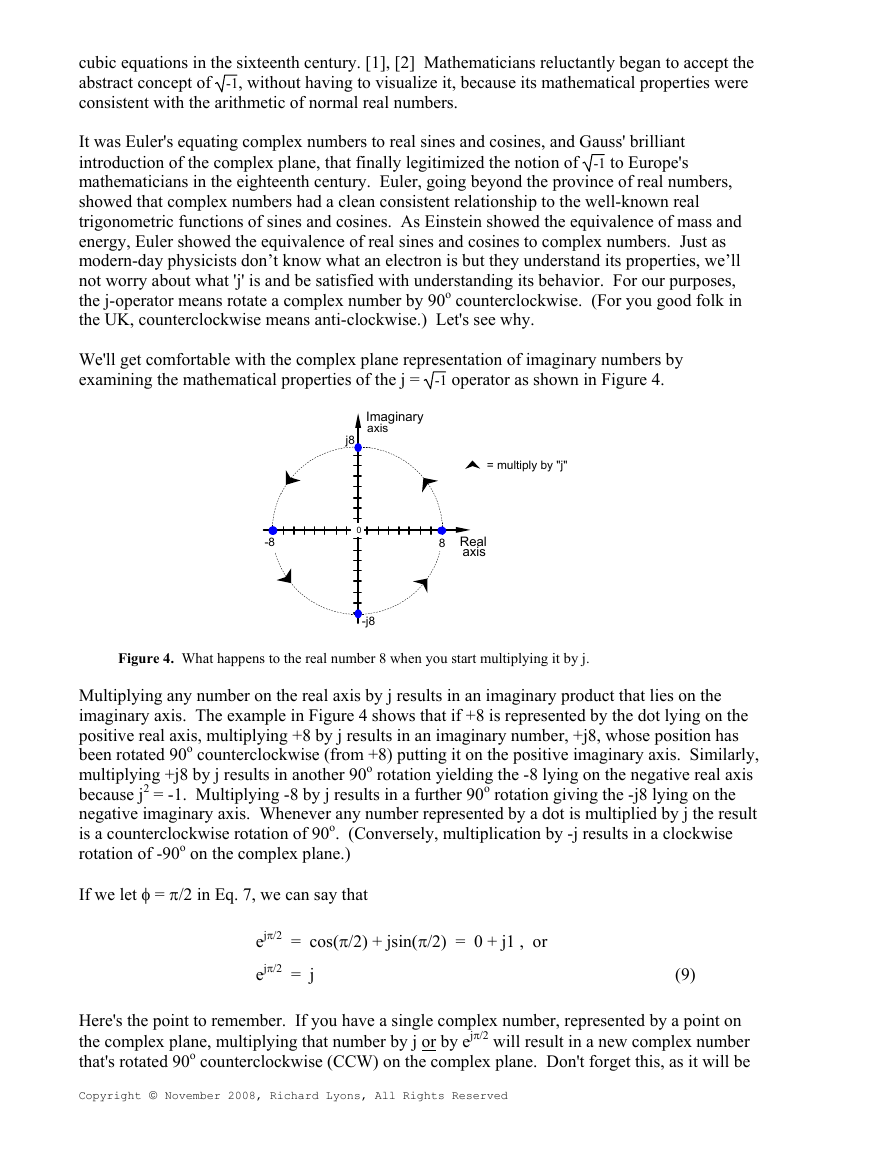
We'll get comfortable with the complex plane representation of imaginary numbers b
e
xamining the mathematical properties of the j =
-1 operator as shown in Figure 4.
ers,
y
d
Imaginary
axis
j8
0
-8
-j8
= multiply by "j"
8
Real
axis
Figure 4. What happens to the real number 8 when you start multiplying it by j.
Multiplying any number on the real axis by j results in an imaginary product that lies on the
imaginary axis. The example in Figure 4 shows that if +8 is represented by the dot lying on the
positive real axis, multiplying +8 by j results in an imaginary number, +j8, whose position has
been rotated 90o counterclockwise (from +8) putting it on the positive imaginary axis. Similarly,
multiplying +j8 by j results in another 90o rotation yielding the -8 lying on the negative real axi
s
because j2 = -1. Multiplying -8 by j results in a further 90o rotation giving the -j8 lying on the
negative imaginary axis. Whenever any number represented by a dot is multiplied by j the resu
is a counterclockwise rotation of 90o. (C
onversely, multiplication by -j results in a clockwise
tation of -90o on the complex plane.)
ro
If
we let φ = π/2 in Eq. 7, we can say that
π/2) + jsin(π/2) = 0 + j1 , or
= cos(
lt
Here's the point to remember. If you have a single complex number, represented by a point on
the complex plane, multiplying that number by j or by ejπ/2 will result in a new complex number
that's rotated 90o counterclockwise (CCW) on the complex plane. Don't forget this, as it will be
Copyright © November 2008, Richard Lyons, All Rights Reserved
jπ/2
e
ejπ/2 = j
(9)
�
seful as you begin reading the literature of quadrature processing systems!
u
Let's pause for a moment here to catch our breath. Don't worry if the ideas of imaginary
numbers and the complex plane seem a little mysterious. It's that way for everyone at first—
you'll get comfortable with them the more you use them. (Remember, the j-operator pu
zzled
Europe's heavyweight mathematicians for hundreds of years.) Granted, not only is the
mathematics of complex numbers a bit strange at first, but the terminology is almost bizarre.
While the term imaginary is an unfortunate one to use, the term complex is downright weird.
When first encountered, the phrase complex numbers makes us think 'complicated numbers'.
This is regrettable because the concept of complex numbers is not really all that complicated.
Just know that the purpose of the above mathematical rigmaro
a
nd (8). Now, let's (finally!) talk about time-domain signals.
R
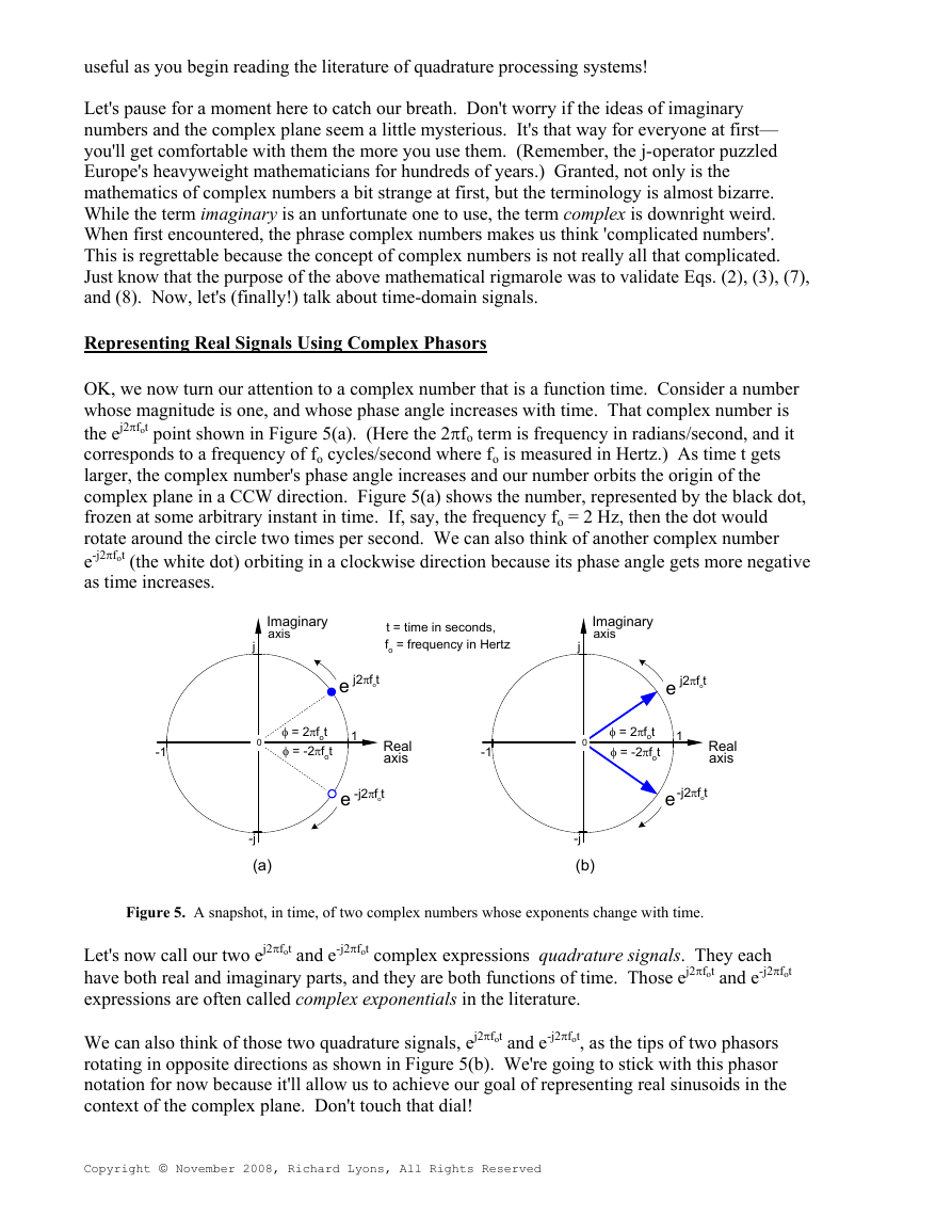
OK, we now turn our attention to a complex number that is a function time. Consider a number
whose magnitude is one, and whose phase angle increases with time. That complex number is
the ej2πfot point shown in Figure 5(a). (Here the 2πfo term is frequency in radians/second, and i
t
corresponds to a frequency of fo cycles/second where fo is measured in Hertz.) As time t ge
ts
larger, the complex number's phase angle increases and our number orbits the origin of the
complex plane in a CCW direction. Figure 5(a) shows the number, represented by the black
frozen at some arbitrary instant in time. If, say, the frequency fo = 2 Hz, then the dot would
rotate around the circle two times per second. We can also think of another complex number
e-j2πfot (the white do
s time increases.
a
epresenting Real Signals Using Complex Phasors
t) orbiting in a clockwise direction because its phase angle gets more negative
le was to validate Eqs. (2), (3), (7),
dot,
Imaginary
axis
j
0
j2πfot
e
φ = 2πfot
φ = -2πfot
1
Real
axis
-j2πfot
e
-j
(b)
Imaginary
axis
j
t = time in seconds,
fo = frequency in Hertz
j2πfot
e
-1
0
φ = 2πfot
φ = -2πfot
1
Real
axis
-1
-j2πfot
e
-j
(a)
Figure 5. A snapshot, in time, of two complex numbers whose exponents change with time.
Let's now call our two ej2πfot and e-j2πfot complex expressions quadrature signals. They each
have both real and imaginary parts, and they are both functions of ti
xpressions are often called complex exponentials in the literature.
e
We can also think of those two quadrature signals, ej2πfot and e-j2πfot, as the tips of two phasors
rotating in opposite directions as shown in Figure 5(b). We're going to stick with this phasor
oal of representing real sinusoids in the
notation for now because it'll allow us to achieve our g
ontext of the complex plane. Don't touch that dial!
c
Copyright © November 2008, Richard Lyons, All Rights Reserved
me. Those ej2πfot and e-j2πfot
�
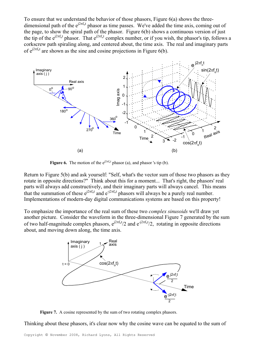
To ensure that we understand the behavior of those phasors, Figure 6(a) shows the three-
dimensional path of the ej2πfot phasor as time passes. We've added the time axis, coming out of
the page, to show the spiral path of the phasor. Figure 6(b) shows a continuous version of just
the tip of the ej2πfot phasor. That ej2πfot complex number, or if you wish, the phasor's tip, follows a
corkscrew path spiraling along, and centered about, the time axis. Th
e real and imaginary parts
f ej2πfot are shown as the sine and cosine projections in Figure 6(b).
o
Imaginary
axis ( j )
Real axis
o
90
o
0
o
180
o
270
(a)
2
1
0
-1
-2
-1
0
1
Time
2
i
s
x
a
g
a
m
I
360o
Time
e j2πfot
sin(2πfot)
1
0
-1
cos(2πfot)
2
x i s
a l a
e
R
3
-2
(b)
Figure 6. The motion of the ej2πfot phasor (a), and phasor 's tip (b).
plementations of modern-day digital communications systems are based on this property!
Return to Figure 5(b) and ask yourself: "Self, what's the vector sum of those two phasors as the
rotate in opposite directions?" Think about this for a moment... That's right, the phasors' real
parts will always add constructively, and their imaginary parts will always cancel. This means
that the summation of these ej2πfot and e-j2πfot phasors will always be a purely real number.
Im
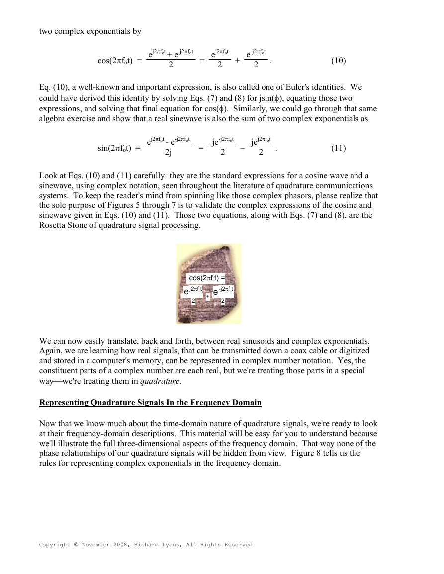
To emphasize the importance of the real sum of these two complex sinusoids we'll draw yet
another picture. Consider the waveform in the three-dimensional Figure 7 generated by the s
and e-j2πfot/2, rotating in opposite directions
of two half-magnitude complex phasors, ej2πfot/2
bout, and moving down along, the time axis.
a
um
y
Imaginary
axis ( j )
1
Real
axis
t = 0
cos(2πfot)
e
j2πfot
2
e
-j2πfot
2
Time
Figure 7. A cosine represented by the sum of two rotating complex phasors.
Thinking about these phasors,
Copyright © November 2008, Richard Lyons, All Rights Reserved
it's clear now why the cosine wave can be equated to the sum of
�
tw
o complex exponentials by
cos(2πfot) =
e
j2πfot e-j2πfot
+
2
=
j
e 2πf
ot
2
+
-j
fot
e 2π
2
.
(10)
Eq. (10), a well-known and important expression, is also called one of Euler's identities. W
could have derived this identity by solving Eqs. (7) and (8) for jsin(φ), equating those two
expressions, and solving that final equation for cos(φ). Similarly, we could go through that sam
lgebra exercise and show that a real sinewave is also the sum of two complex exponentials as
a
e
e
sin(2πfot) =
j2πfo
e
t - e
2j
-j2πfot
=
je-j2π
fot
2
–
jej2π
fot
2
.
(11)
Look at Eqs. (10) and (11) carefully−they are the standard expressions for a cosine wave and a
sinewave, using complex notation, seen throughout the literature of quadrature communications
systems. To keep the reader's mind from spinning like those complex phasors, please realize tha
the sole purpose of Figures 5 through 7 is to validate the complex expressions of the cosine and
sinewave given in Eqs. (10) and (11). Those tw
o equations, along with Eqs. (7) and (8), are the
osetta Stone of quadrature signal processing.
R
t
cos(2πfot) =
ej2πfot
e
+
-j2πfot
2
2
We can now easily translate, back and forth, between real sinusoids and complex exponentials.
Again, we are learning how real signals, that can be transmitted down a coax cable or digitized
and stored in a computer's memory, can be represented in complex number notation. Yes, the
constituent parts of a complex number are
each real, but we're treating those parts in a special
ay⎯we're treating them in quadrature.
w
R
Now that we know much about the time-domain nature of quadrature signals, we're ready to look
at their frequency-domain descriptions. This material will be easy for you to understand because
the
we'll illustrate the full three-dimensional aspects of the frequency domain. That way none of
Figure 8 tells us the
phase relationships of our quadrature signals will be hidden from view.
les for representing complex exponentials in the frequency domain.
ru
epresenting Quadrature Signals In the Frequency Domain
Copyright © November 2008, Richard Lyons, All Rights Reserved
�



 2023年江西萍乡中考道德与法治真题及答案.doc
 2012年重庆南川中考生物真题及答案.doc
 2013年江西师范大学地理学综合及文艺理论基础考研真题.doc
 2020年四川甘孜小升初语文真题及答案I卷.doc
 2020年注册岩土工程师专业基础考试真题及答案.doc
 2023-2024学年福建省厦门市九年级上学期数学月考试题及答案.doc
 2021-2022学年辽宁省沈阳市大东区九年级上学期语文期末试题及答案.doc
 2022-2023学年北京东城区初三第一学期物理期末试卷及答案.doc
 2018上半年江西教师资格初中地理学科知识与教学能力真题及答案.doc
 2012年河北国家公务员申论考试真题及答案-省级.doc
 2020-2021学年江苏省扬州市江都区邵樊片九年级上学期数学第一次质量检测试题及答案.doc
 2022下半年黑龙江教师资格证中学综合素质真题及答案.doc