Rikaline GPS-24 / 24A
GPS Receiver Board
User’s Guide
Nemerix V1.0 Feb 28, 2005
Rikaline International Corp.
14F, 171, ChengGong Rd., Sanchong City, Taipei 241, Taiwan, R.O.C
Phone: +886-2-8973-1899 Fax: +886-2-8973-1896
E-Mail: info@rikaline.com.tw Web: www.rikaline.com.tw
All Right Reserved
�
GPS Receiver Board GPS-24 / 24A Operating Manual Rikaline
1. Introduction
1.1 Overview
The Rikaline GPS-24 / 24A is a GPS receiver board featuring Nemerix low power architecture. This
complete enabled GPS receiver board provides high position and speed accuracy performances as well as
high sensitivity and tracking capabilities in urban canyon conditions. The solution enables small form factor
package. The GPS-24 / 24A delivers major advancements in GPS performances, accuracy, integration,
computing power and flexibility. It is designed to simplify the embedded system integration process.
This positioning application meets strict needs such as car navigation, mapping, surveying, agriculture and
so on. Only clear view of sky and certain power supply are necessary to the unit. GPS-24 / 24A
communicates with other electronic utilities via compatible dual-channel through TTL and saves critical
satellite data in built–in memory backup. With low power consumption, the GPS-24 / 24A tracks up to 16
satellites at a time, re-acquires satellite signals in 100 ms and updates position data every second.
1.2 Features
The GPS-24 / 24A provides a host of features that make it easy for integration and use.
1. Position accuracy in < 7m CEP (90%) without SA (horizontal)
2. Ultra low power: 30mW typical -- tracking at 3.3 Volts, full power
3. High sensitivity: to -152 dBm tracking, superior urban canyon performances
4. Small form factor and low cost solution
5. Ready-to-plug solution. Easily integrated into existing systems
6. On-board RAM for GPS navigation data
7. PPS output (User may have different interval setting from 1 second to 1 minute.
8. Differential capability utilizes real-time RTCM corrections producing < 1 meter position accuracy.
9. FLASH based program memory: New setting is stored permanently.
1.3 Application
1. Car Navigation
2. Mapping
3. Surveying
4. Agriculture
5. Palmtop, Laptop, PDA
6. Location Based Services enabled devices
7. Asset management/tracking
8. Handheld receivers
9. Radar detector with GPS function
1.4 Technology specifications
1.4.1 Physical Dimension
1. Size: 25.9(W) x 25.9(D) x 2.7(H) (mm)
1.02”(W) x 1.02”(D) x 0.11”(H)
2. Weight: 21 g
1.4.2 Environmental Characteristics
1) Operating temperature: -40oC to +80oC (internal temperature)
2) Storage temperature: -55oC to +100oC
1.4.3 Electrical Characteristics
1)
2) MMCX antenna connector: Active or patch (3.0V antenna is recommended).
1.4.4 Performance
1) Tracks up to 16 satellites.
2) Update rate: 1 second.
3) Sensitivity:
Input voltage: +3.3 ±5% VDC.
Specifications subject to change without prior notice
Rikaline International Corp. 14F, 171, ChengGong Rd, Sanchong CityTaipei 241, Taiwan
Tel: ++886 2 8973 1899 Fax: ++886 2 8973 1896 E-Mail: info@rikaline.com.tw Web: www.rikaline.com.tw
2
�
GPS Receiver Board GPS-24 / 24A Operating Manual Rikaline
Tracking: -152dBm
Acquisition: -139dBm
3) Acquisition time:
Reacquisition
Hot start
Warm start
Cold start
4) Position accuracy:
0.1 sec. (90%)
12 sec. (90%)
38 sec. (90%)
60 sec. (90%)
Non DGPS (Differential GPS)
Position
Velocity
Time
DGPS (Differential GPS)
<7m CEP (90%) with S\A off
0.1 meters/second.
1 microsecond synchronized GPS time
Position
Velocity
<1 m, typical
0.05 meters/second, typical
5) Dynamic Conditions:
10,000 meters(32,800 feet) max
Altitude
Velocity
Horisontal 300 Km/Hr
Vertical 36 Km/Hr
2 G, max
Acceleration
Jerk
4 meters/second³, max
6) Time-1PPS Pulse (optional)
Level
Pulse duration
Time reference
Measurements
TTL
100ms
at the pulse positive edge
Aligned to GPS second, +-1 microsecond
7) 2.1.10 Recommended External Antenna Specification
Gain
Noise figure
Current
Operate Voltage
20dB (including cable loss)
1.5dB
3 ~ 30mA
2.5 ~ 2.8V
1.4.5 Interfaces
1) Dual communication channel through TTL, with user selectable baud rate (4800, 9600-Default, 19200,
38400).
2) NMEA 0183 Version 3.0 ASCII output (GGA, GSV(3), GSA(3), RMC, VTG).
3) Real-time Differential Correction input (RTCM SC-104 message types 1, 2 and 9).
Specifications subject to change without prior notice
Rikaline International Corp. 14F, 171, ChengGong Rd, Sanchong CityTaipei 241, Taiwan
Tel: ++886 2 8973 1899 Fax: ++886 2 8973 1896 E-Mail: info@rikaline.com.tw Web: www.rikaline.com.tw
3
�
GPS Receiver Board GPS-24 / 24A Operating Manual Rikaline
2. Operational characteristics
2.1 Initialization
As soon as the initial self-test is complete, the GPS-22 begins the process of satellite acquisition and
tracking automatically. Under normal circumstances, it takes approximately 120 seconds to achieve a
position fix, 42 seconds if ephemeris data is known. After a position fix has been calculated, information
about valid position, velocity and time is transmitted over the output channel.
The GPS-22 utilizes initial data, such as last stored position, date, time and satellite orbital data, to achieve
maximum acquisition performance. If significant inaccuracy exists in the initial data, or the orbital data is
obsolete, it may take more time to achieve a navigation solution. The FirstGPS™ architecture provides
superior performance. However, acquisition performance can be improved as the host system initializes the
GPS-22 in the following situation:
1. Moving further than 1,500 kilometers.
2. Failure of Data storage due to the inactive memory power back up.
2.2 Navigation
After the acquisition process is complete, the GPS-22 sends valid navigation information over output
channels. These data include:
1) Latitude/longitude/altitude
2) Velocity
3) Date/time
4) Error estimates
5) Satellite and receiver status
The GPS-22 sets the default of auto-searching for real-time differential corrections in RTCM SC-104
standard format, with the message types 1, 2, or 9. It accomplishes the satellite data to generate a
differential (DGPS) solution. The host system, at its option, may also command the GPS-22 to output a
position whenever a differential solution is available.
Specifications subject to change without prior notice
Rikaline International Corp. 14F, 171, ChengGong Rd, Sanchong CityTaipei 241, Taiwan
Tel: ++886 2 8973 1899 Fax: ++886 2 8973 1896 E-Mail: info@rikaline.com.tw Web: www.rikaline.com.tw
4
�
GPS Receiver Board GPS-24 / 24A Operating Manual Rikaline
3. Hardware interface
3.1 Physical Characters
1. Size: 25.9(W) x 25.9(D) x 2.7(H) (mm) 2. Weight: 25 g
1.02”(W) x 1.02”(D) x 0.11”(H)
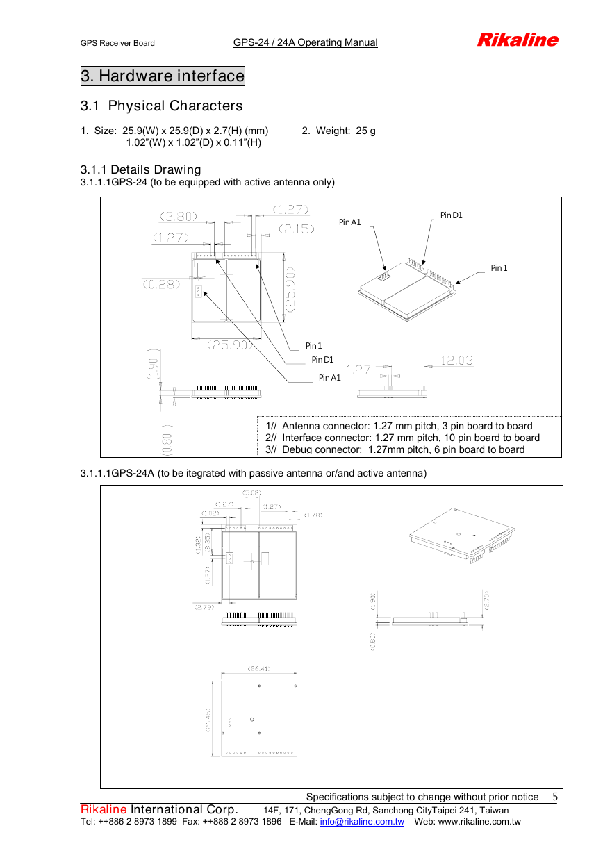
3.1.1 Details Drawing
3.1.1.1GPS-24 (to be equipped with active antenna only)
Pin A1
Pin D1
Pin 1
Pin 1
Pin D1
Pin A1
1// Antenna connector: 1.27 mm pitch, 3 pin board to board
2// Interface connector: 1.27 mm pitch, 10 pin board to board
3// Debug connector: 1.27mm pitch, 6 pin board to board
3.1.1.1GPS-24A (to be itegrated with passive antenna or/and active antenna)
Specifications subject to change without prior notice
Rikaline International Corp. 14F, 171, ChengGong Rd, Sanchong CityTaipei 241, Taiwan
Tel: ++886 2 8973 1899 Fax: ++886 2 8973 1896 E-Mail: info@rikaline.com.tw Web: www.rikaline.com.tw
5
�
Reserved, keep float
Low Active, keep float if not use *1 Will not effect hot, or cold start
Backup Battery Input (1.2~2V)
PIN
1
2
3
4
5
6
7
8
9
10
A1
A2
A3
D1
D2
D3
D4
D5
D6
NAME
GPIO(4)
NC (MODE)
NMEA Tx
NMEA Rx
NC (WAKE UP) NU
I
Reset
VBAT
I
GND
VCC
GPIO(0)
RF GND
RF IN
RF GND
DSUMUX
DSUEN
DSUBRE
DSUTX
DSURX
DSUACT
I
I
I
O
I
O
DESCRIPTION
TYPE
I \ O GPS Status
NU
I \ O NMEA Serial Data Output
I \ O NMEA Serial Data Input
Reserved, keep float
PWR Ground
PWR +3.0~3.6V DC Power Input
I \ O SW dependent functions
ANT Antenna ground
ANT Antenna +
ANT Antenna ground
Serial / DSU select
DSU enable
DSU break enable
DSU transmitter
DSU receiver
DSU active
GPS Receiver Board GPS-24 / 24A Operating Manual Rikaline
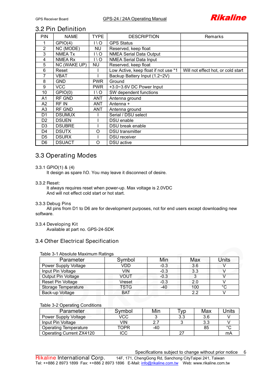
3.2 Pin Definition
Remarks
3.3 Operating Modes
3.3.1 GPIO(1) & (4)
It design as spare I\O. You may leave it disconnect of desire.
3.3.2 Reset:
It always requires reset when power-up. Max voltage is 2.0VDC
And will not effect cold start or hot start.
3.3.3 Debug Pins
All pins from D1 to D6 are for development purposes, not for end users except downloading new
software.
3.3.4 Developing Kit
Available at part no. GPS-24-SDK
3.4 Other Electrical Specification
Table 3-1 Absolute Maximum Ratings
Parameter
Power Supply Voltage
Input Pin Voltage
Output Pin Voltage
Reset Pin Voltage
Storage Temperature
Back-up Voltage
Symbol
VDD
VIN
VOUT
Vreset
TSTG
BAT
Table 3-2 Operating Conditions
Parameter
Power Supply Voltage
Input Pin Voltage
Operating Temperature
Operating Current ZX4120
Symbol
VCC
VIN
TOPR
ICC
Min
-0.3
-0.3
-0.3
-0.3
-40
Max
3.6
3.3
3
2.0
100
2.2
Units
V
V
V
V
°C
V
Min
3
2.7
-40
Typ
3.3
3
27
Max
3.6
3.3
85
Units
V
V
°C
mA
Specifications subject to change without prior notice
Rikaline International Corp. 14F, 171, ChengGong Rd, Sanchong CityTaipei 241, Taiwan
Tel: ++886 2 8973 1899 Fax: ++886 2 8973 1896 E-Mail: info@rikaline.com.tw Web: www.rikaline.com.tw
6
�
GPS Receiver Board GPS-24 / 24A Operating Manual Rikaline
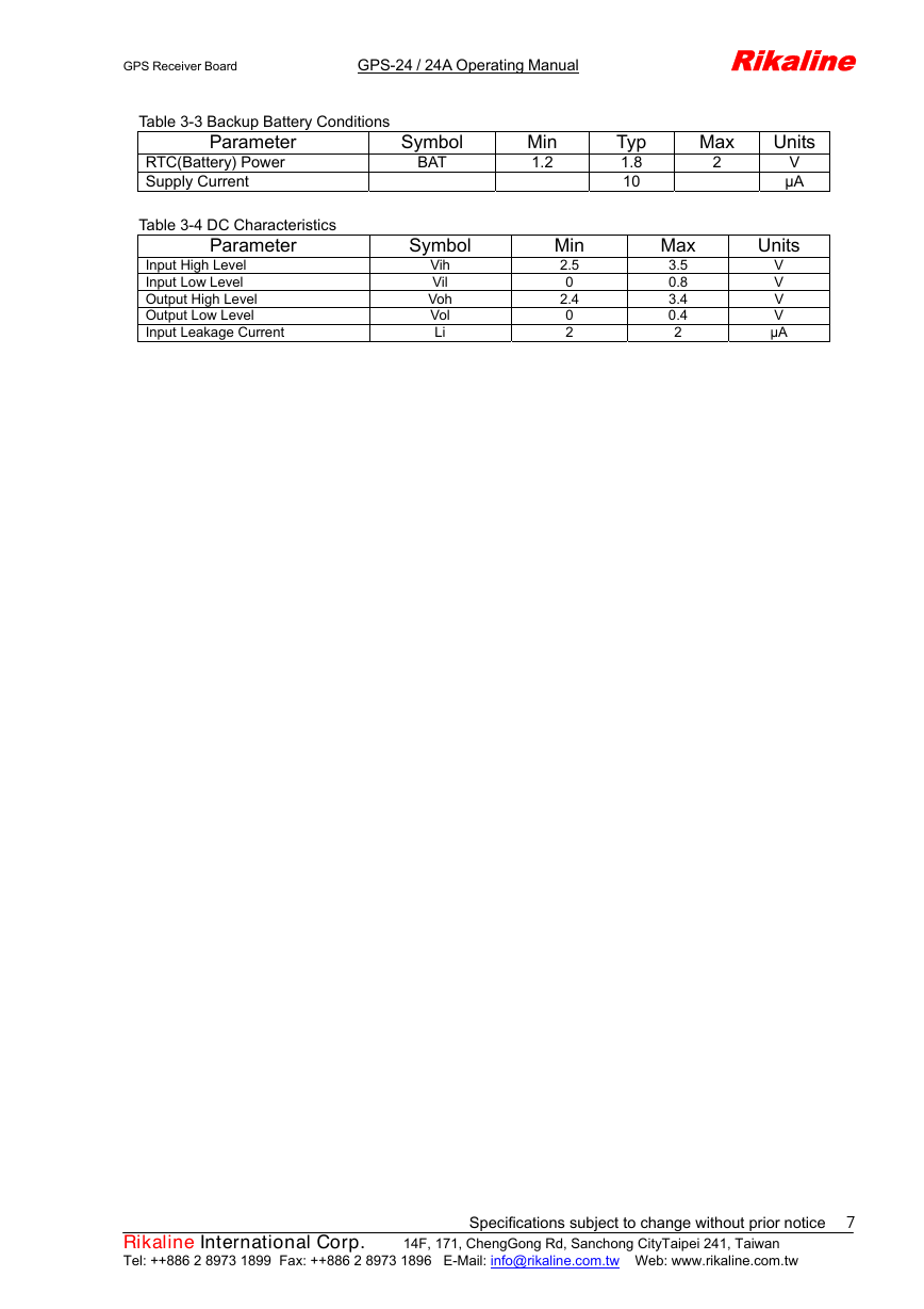
Table 3-3 Backup Battery Conditions
Parameter
RTC(Battery) Power
Supply Current
Symbol
BAT
Table 3-4 DC Characteristics
Parameter
Input High Level
Input Low Level
Output High Level
Output Low Level
Input Leakage Current
Symbol
Vih
Vil
Voh
Vol
Li
Min
1.2
Typ
1.8
10
Max
2
Units
V
µA
Min
2.5
0
2.4
0
2
Max
3.5
0.8
3.4
0.4
2
Units
V
V
V
V
µA
Specifications subject to change without prior notice
Rikaline International Corp. 14F, 171, ChengGong Rd, Sanchong CityTaipei 241, Taiwan
Tel: ++886 2 8973 1899 Fax: ++886 2 8973 1896 E-Mail: info@rikaline.com.tw Web: www.rikaline.com.tw
7
�
GPS Receiver Board GPS-24 / 24A Operating Manual Rikaline
4. Software Interface
The GPS-24 / 24A interface protocol is based on the National Marine Electronics Association's NMEA 0183
ASCⅡ interface specification, which is defined in NMEA 0183, Version 3.0 and the Radio Technical
Commission for Maritime Services (RTCM Recommended Standards For Differential Navstar GPS Service,
Version 2.1, RTCM Special Committee No.104).
4.1 NMEA Transmitted Messages
The GPS-24 / 24A outputs data in NMEA-0183 format as defined by the National Marine Electronics
Association (NMEA), Standard.
The default communication parameters for NMEA output are 9600 baud, 8 data bits, stop bit, and no parity.
The default communication parameters for DGPS Input are 9600 baud, 8 data bits, stop bit, and no
parity. Position accuracy of less than 5 meters can be achieved with the GPS-24 / 24A by using Differential
GPS (DGPS) real-time pseudo-range correction data in RTCM SC-104 format, with message types 1, 5, or
9. As using DGPS receiver with different communication parameters, GPS-24 / 24A may decode the data
correctly to generate accurate messages and save them in battery-back SRAM for later computing.
4.3 Earth Datums
The GPS-24 / 24A is built in earth datum with WGS84.
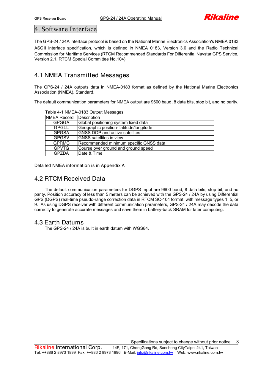
Table 4-1 NMEA-0183 Output Messages
NMEA Record Description
GPGGA
GPGLL
GPGSA
GPGSV
GPRMC
GPVTG
GPZDA
Global positioning system fixed data
Geographic position- latitude/longitude
GNSS DOP and active satellites
GNSS satellites in view
Recommended minimum specific GNSS data
Course over ground and ground speed
Date & Time
Detailed NMEA information is in Appendix A
4.2 RTCM Received Data
Specifications subject to change without prior notice
Rikaline International Corp. 14F, 171, ChengGong Rd, Sanchong CityTaipei 241, Taiwan
Tel: ++886 2 8973 1899 Fax: ++886 2 8973 1896 E-Mail: info@rikaline.com.tw Web: www.rikaline.com.tw
8
�




 2023年江西萍乡中考道德与法治真题及答案.doc
 2012年重庆南川中考生物真题及答案.doc
 2013年江西师范大学地理学综合及文艺理论基础考研真题.doc
 2020年四川甘孜小升初语文真题及答案I卷.doc
 2020年注册岩土工程师专业基础考试真题及答案.doc
 2023-2024学年福建省厦门市九年级上学期数学月考试题及答案.doc
 2021-2022学年辽宁省沈阳市大东区九年级上学期语文期末试题及答案.doc
 2022-2023学年北京东城区初三第一学期物理期末试卷及答案.doc
 2018上半年江西教师资格初中地理学科知识与教学能力真题及答案.doc
 2012年河北国家公务员申论考试真题及答案-省级.doc
 2020-2021学年江苏省扬州市江都区邵樊片九年级上学期数学第一次质量检测试题及答案.doc
 2022下半年黑龙江教师资格证中学综合素质真题及答案.doc