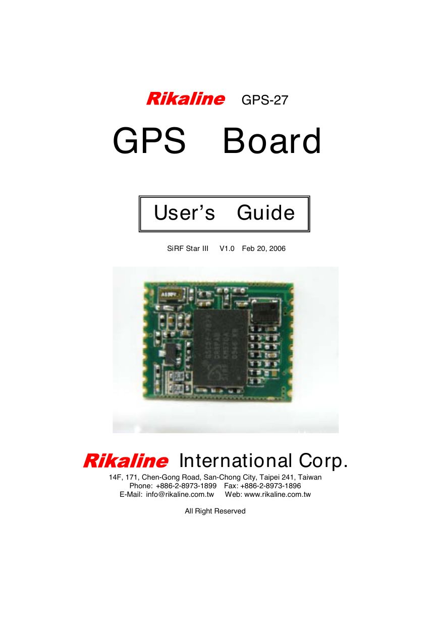
Rikaline GPS-27
GPS Board
User’s Guide
SiRF Star III V1.0 Feb 20, 2006
Rikaline International Corp.
14F, 171, Chen-Gong Road, San-Chong City, Taipei 241, Taiwan
Phone: +886-2-8973-1899 Fax: +886-2-8973-1896
E-Mail: info@rikaline.com.tw Web: www.rikaline.com.tw
All Right Reserved
�
GPS-27 Operating Manual Rikaline
TABLE OF CONTENTS
3
3
3
3
1. Introduction ………………………………………………………………………………………..
1.1 Overview ……………………………………………………………………………………..
1.2 Features ……………………………………………………………………………………..
1.3 Technical Specifications ………………………………………………………………..
2. Operational Characteristics ……………………………………………………………….… 5
5
5
2.1 Initialization ………………………………………………………………………………….
2.2 Navigation ………………………………………………………………………………….
3. Hardware Interface ………………………………………………………………………….…… 6
3.1 Physical Characteristics ……………………………………………………………….… 6
3.2 Hardware …..…………………..……………………………………………………….…… 6
3.3 Connector ………………………………………………………………………………….… 6
3.4 Pad Assignment …………………………………………………………………………… 6
3.5 Other function description …………………………………………..………………… 8
4. Software Interface …………………………………………………………………………….… 9
4.1 NMEA Transmitted Sentences ……………………………………………………..… 9
4.2 RTCM Received Data ………………………………………………………………….. 12
5. Earth Datums & Output Setting ……………………………………………………………. 13
5.1 Earth Datums ……………………………………………………………………………….. 13
5.2 Output Setting …………………………………………………………………………….… 13
6. Ordering Information ………………………………………………………………………..… 14
6.1 Product Options ………………………………………………………………….………… 14
6.2 Accessories ………………………………………………………………………….……… 14
7. Warranty ……………………………………………………………………………………………… 14
Rikaline International Corp. 14F, 171, Cheng-Gong Road, SanChung City, Taipei 241, Taiwan
Tel: ++886 2 8973 1899 Fax: ++886 2 8973 1896 E-Mail: info@rikaline.com.tw web: www.rikaline.com.tw
2
�
GPS-27 Operating Manual Rikaline
1. Introduction
1.1 Overview
The Rikaline GPS-27 GPS Engine Board is designed based on SiRF Star III new generation
architecture with low power consumption, small size (16 x 20mm) and easy integrated for a broad spectrum
of OEM system applications. It acquires satellite 20 channel parallel and tracking 12 at a time. The 200,000
effective correlators ensure fast TTFF and fast TTFF at low signal level.
The GPS-27 meets strict needs such as car navigation, mapping, surveying, security, agriculture and so on.
Only clear view of sky and certain power supply are necessary to the unit. It communicates with other
electronic utilities via compatible TTL and saves critical satellite data by built–in backup memory. The
Trickle-Power allows the unit operates a fraction of the time and Push-to-Fix permits user to have a quick
position fix even though the receiver usually stays off.
To minimize the space and cost, we provide you GPS-27 without patch antenna and some components
which you may have in your main board.
1.2 Features
The GPS-27 provides a host of features that make it easy for integration and use.
1. SiRF Star III chipset with embedded ARM7TDMI CPU available for customized applications in
2. High performance receiver acquires 20 channel parallel and tracks up to 12 satellites while providing first
fast fix and low power consumption.
3. Differential capability utilizes real-time RTCM corrections producing 1-5 meter position accuracy.
4. Compact design ideal for applications with minimal space.
5. User initialization is not required.
6. Dual communication channels and user selectable baud rates allow maximum interface capability and
firmware.
flexibility.
7. Optional customer design for any possible size down to 16 x 20mm.
8. FLASH based program memory: New software revisions upgradeable through serial interface.
9. Built-in WAAS and EGNOS demodulator.
1.3 Technical specifications
1.3.1 Physical Characteristics
Dimension: 16(L) x 20(W) x 3(H) mm
0.63"(L) x 0.79"(W) x 0.12"(H).
Weight: 2.8g
1.3.2 Environmental Characteristics
1) Operating temperature: -40oC to +85oC
2) Storage temperature: -55oC to +100oC.
1.3.3 Electrical Characteristics
1)
Input voltage: +2.85Vdc (Base Band & RF) and +1.5Vdc (RTC)
1.3.4 Performance
1) Acquisition: 20 channel parallel
2) Tracking: up to 12 satellites
3) Update rate: 1 second
4) Acquisition time
Rikaline International Corp. 14F, 171, Cheng-Gong Road, SanChung City, Taipei 241, Taiwan
Tel: ++886 2 8973 1899 Fax: ++886 2 8973 1896 E-Mail: info@rikaline.com.tw web: www.rikaline.com.tw
3
�
GPS-27 Operating Manual Rikaline
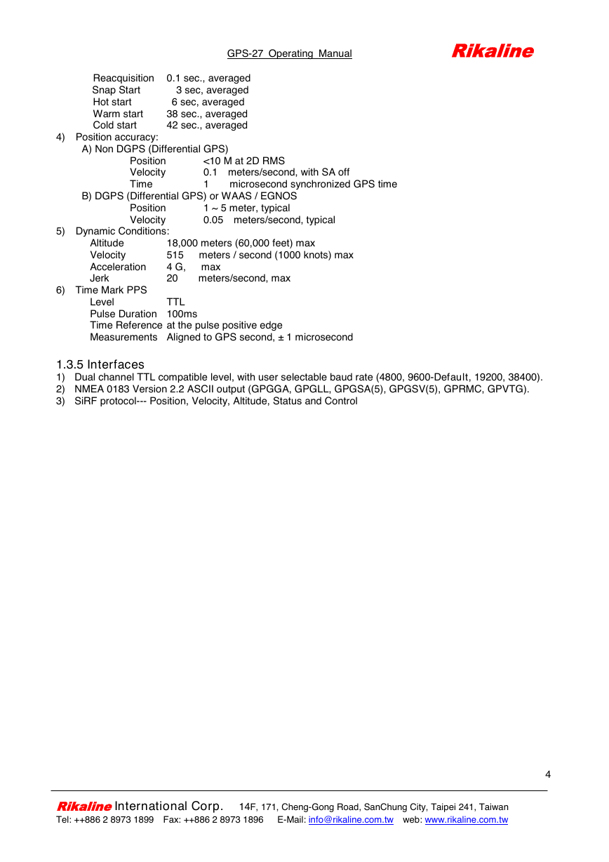
Reacquisition 0.1 sec., averaged
Snap Start 3 sec, averaged
6 sec, averaged
38 sec., averaged
42 sec., averaged
4) Position accuracy:
Hot start
Warm start
Cold start
A) Non DGPS (Differential GPS)
Position
Velocity
Time
<10 M at 2D RMS
0.1 meters/second, with SA off
1 microsecond synchronized GPS time
B) DGPS (Differential GPS) or WAAS / EGNOS
1 ~ 5 meter, typical
0.05 meters/second, typical
Position
Velocity
5) Dynamic Conditions:
6) Time Mark PPS
Altitude
Velocity
Acceleration
Jerk
18,000 meters (60,000 feet) max
515 meters / second (1000 knots) max
4 G, max
20 meters/second, max
TTL
Level
Pulse Duration 100ms
Time Reference at the pulse positive edge
Measurements Aligned to GPS second, ± 1 microsecond
1.3.5 Interfaces
1) Dual channel TTL compatible level, with user selectable baud rate (4800, 9600-Default, 19200, 38400).
2) NMEA 0183 Version 2.2 ASCII output (GPGGA, GPGLL, GPGSA(5), GPGSV(5), GPRMC, GPVTG).
3) SiRF protocol--- Position, Velocity, Altitude, Status and Control
Rikaline International Corp. 14F, 171, Cheng-Gong Road, SanChung City, Taipei 241, Taiwan
Tel: ++886 2 8973 1899 Fax: ++886 2 8973 1896 E-Mail: info@rikaline.com.tw web: www.rikaline.com.tw
4
�
2. Operational characteristics
GPS-27 Operating Manual Rikaline
2.1 Initialization
As soon as the initial self-test is complete, the GPS-27 begins the process of satellite acquisition and
tracking automatically. Under normal circumstances, it takes approximately 42 seconds to achieve a position
fix, 38 seconds if ephemeris data is known. After a position fix has been calculated, information about valid
position, velocity and time is transmitted over the output channel.
The GPS-27 utilizes initial data, such as last stored position, date, time and satellite orbital data, to achieve
maximum acquisition performance. If significant inaccuracy exists in the initial data, or the orbital data is
obsolete, it may take more time to achieve a navigation solution. The GPS-27 Auto-locate feature is capable
of automatically determining a navigation solution without intervention from the host system.
2.2 Navigation
After the acquisition process is complete, the GPS-27 sends valid navigation information over
output channels. These data include:
1) Latitude/longitude/altitude
2) Velocity
3) Date/time
4) Error estimates
5) Satellite and receiver status
The GPS-27 sets the default of auto-searching for real-time differential corrections in RTCM SC-104
standard format, with the message types 1, 5, or 9. It accomplishes the satellite data to generate a differential
(DGPS) solution. The host system, at its option, may also command the GPS-27 to output a position
whenever a differential solution is available.
Rikaline International Corp. 14F, 171, Cheng-Gong Road, SanChung City, Taipei 241, Taiwan
Tel: ++886 2 8973 1899 Fax: ++886 2 8973 1896 E-Mail: info@rikaline.com.tw web: www.rikaline.com.tw
5
�
GPS-27 Operating Manual Rikaline
3. Hardware interface
3.1 Physical Characteristics
Dimension: 16(L) x 20(W) x 3(H) mm
0.63"(L) x 0.79"(W) x 0.12"(H).
Weight: 2.8g
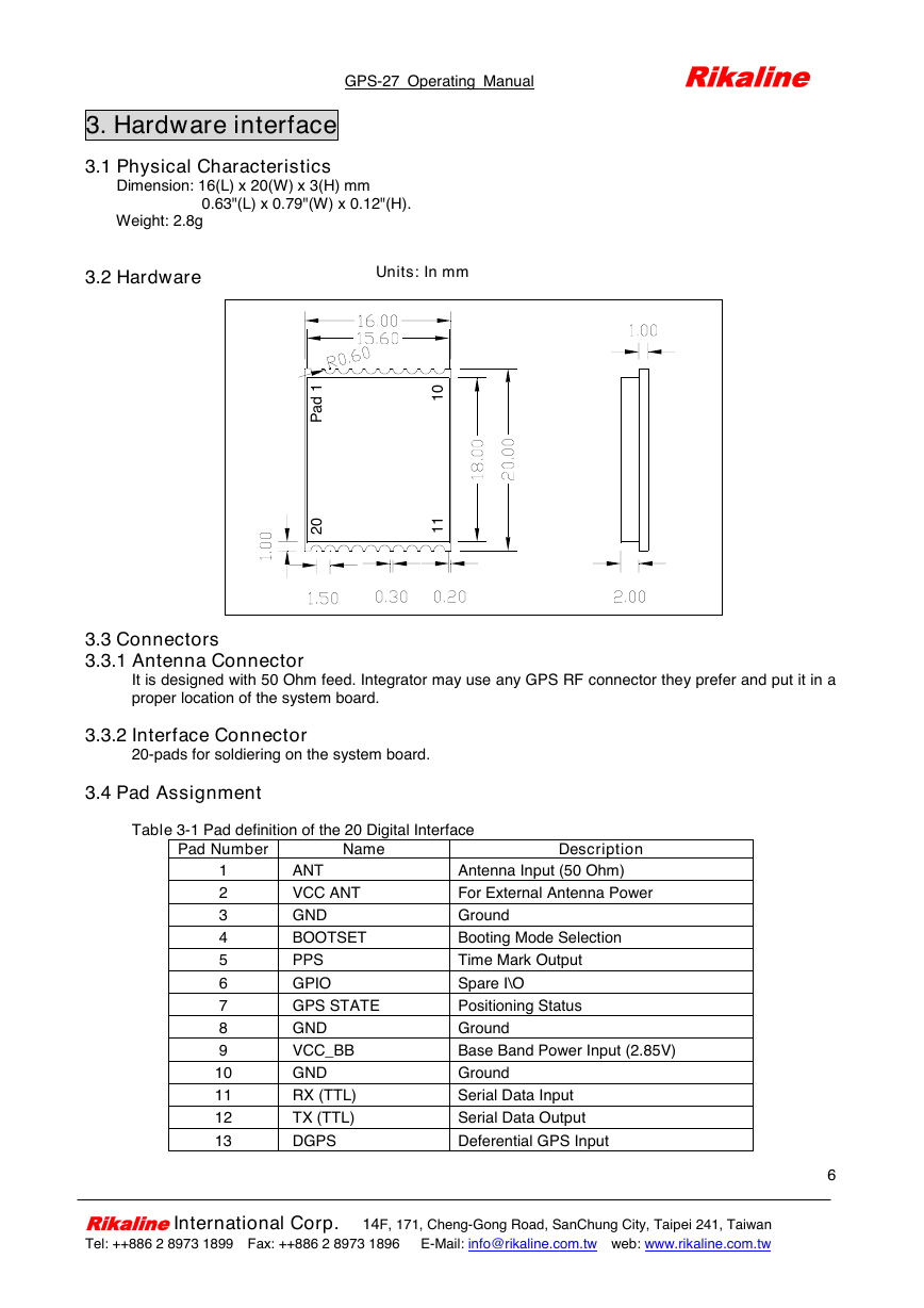
3.2 Hardware
Units: In mm
1
d
a
P
0
1
0
2
1
1
3.3 Connectors
3.3.1 Antenna Connector
3.3.2 Interface Connector
20-pads for soldiering on the system board.
3.4 Pad Assignment
It is designed with 50 Ohm feed. Integrator may use any GPS RF connector they prefer and put it in a
proper location of the system board.
Table 3-1 Pad definition of the 20 Digital Interface
Pad Number
Name
Description
1
2
3
4
5
6
7
8
9
10
11
12
13
ANT
VCC ANT
GND
BOOTSET
PPS
GPIO
GPS STATE
GND
VCC_BB
GND
RX (TTL)
TX (TTL)
DGPS
Antenna Input (50 Ohm)
For External Antenna Power
Ground
Booting Mode Selection
Time Mark Output
Spare I\O
Positioning Status
Ground
Base Band Power Input (2.85V)
Ground
Serial Data Input
Serial Data Output
Deferential GPS Input
Rikaline International Corp. 14F, 171, Cheng-Gong Road, SanChung City, Taipei 241, Taiwan
Tel: ++886 2 8973 1899 Fax: ++886 2 8973 1896 E-Mail: info@rikaline.com.tw web: www.rikaline.com.tw
6
�
GPS-27 Operating Manual Rikaline
14
15
16
17
18
19
20
P-T-F
VCC_RTC
GND
VCC_RF
RESET
GND
GND
Push-To-Fix
RTC Back up (1.5V)
Ground
RF Input (2.85V)
System Restart
Ground
Ground
Table 3-2 Operating Conditions
Parameter
Power Supply Voltage
Power Supply Voltage
Operating Temperature
Operating Current
Symbol
VCC (BB & RF)
VCC (RTC)
TOPR
ICC
Table 3-3 Battery Conditions
Parameter
RTC (Battery) Power
Supply Current
Symbol
VCC_RTC
Min
2.7
1.4
-40
Min
1.4
Type
2.85
1.5
90
Typ
1.5
10
Max
2.8
1.6
85
Max
1.6
Units
V
V
ºC
mA
Units
V
µA
3.4.1 Antenna Input
For antenna power input.
3.4.2 VCC ANT
For powering the active antenna. We provide you a flexible voltage of the antenna. It depends on your
design either 3.3V, 5V or others.
3.4.3 BOOT SET
For booting mode selection.
3.4.4 PPS Time mark
This function provides 1 pulse per second output from the board, which is synchronized to within 1
microsecond of GPS time. The output is a CMOS (TTL) level signal.
3.4.5 SPARE GPIO Functions
This I/Os of CPU is connected to the digital interface connector for consumer applications.
3.4.6 GPS State
To have GPS positioning status visible. Default (to LED): Blinking (Power ON) and ON (position fix)
3.4.7 VCC BASE BAND
It requires 2.85Vdc stable power input for the base band.
3.4.8 Rx (TTL)
This pad is for data Input to control the GPS output or GPS system setting
3.4.9 Tx (TTL)
It outputs standard NMEA 0183 V2.2 sentences, SiRF binary or either one of NMEA and SiRF binary
with customer’s software.
3.4.10 DGPS
Rikaline International Corp. 14F, 171, Cheng-Gong Road, SanChung City, Taipei 241, Taiwan
Tel: ++886 2 8973 1899 Fax: ++886 2 8973 1896 E-Mail: info@rikaline.com.tw web: www.rikaline.com.tw
7
�
GPS-27 Operating Manual Rikaline
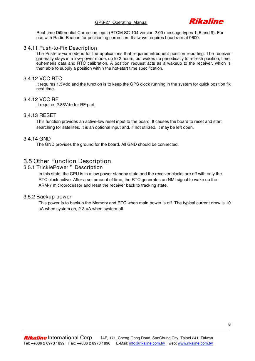
Real-time Differential Correction input (RTCM SC-104 version 2.00 message types 1, 5 and 9). For
use with Radio-Beacon for positioning correction. It always requires baud rate at 9600.
3.4.11 Push-to-Fix Description
3.4.12 VCC RTC
3.4.12 VCC RF
It requires 2.85Vdc for RF part.
3.4.13 RESET
The Push-to-Fix mode is for the applications that requires infrequent position reporting. The receiver
generally stays in a low-power mode, up to 2 hours, but wakes up periodically to refresh position, time,
ephemeris data and RTC calibration. A position request acts as a wakeup to the receiver, which is
then able to supply a position within the hot-start time specification.
It requires 1.5Vdc and the function is to keep the GPS clock running in the system for quick position fix
next time.
This function provides an active-low reset input to the board. It causes the board to reset and start
searching for satellites. It is an optional input and, if not utilized, it may be left open.
3.4.14 GND
The GND provides the ground for the board. All GND should be connected.
3.5 Other Function Description
3.5.1 TricklePowerTM
In this state, the CPU is in a low power standby state and the receiver clocks are off with only the
Description
RTC clock active. After a set amount of time, the RTC generates an NMI signal to wake up the
ARM-7 microprocessor and reset the receiver back to tracking state.
3.5.2 Backup power
This power is to backup the Memory and RTC when main power is off. The typical current draw is 10
µA when system on, 2-3 µA when system off.
Rikaline International Corp. 14F, 171, Cheng-Gong Road, SanChung City, Taipei 241, Taiwan
Tel: ++886 2 8973 1899 Fax: ++886 2 8973 1896 E-Mail: info@rikaline.com.tw web: www.rikaline.com.tw
8
�




 2023年江西萍乡中考道德与法治真题及答案.doc
 2012年重庆南川中考生物真题及答案.doc
 2013年江西师范大学地理学综合及文艺理论基础考研真题.doc
 2020年四川甘孜小升初语文真题及答案I卷.doc
 2020年注册岩土工程师专业基础考试真题及答案.doc
 2023-2024学年福建省厦门市九年级上学期数学月考试题及答案.doc
 2021-2022学年辽宁省沈阳市大东区九年级上学期语文期末试题及答案.doc
 2022-2023学年北京东城区初三第一学期物理期末试卷及答案.doc
 2018上半年江西教师资格初中地理学科知识与教学能力真题及答案.doc
 2012年河北国家公务员申论考试真题及答案-省级.doc
 2020-2021学年江苏省扬州市江都区邵樊片九年级上学期数学第一次质量检测试题及答案.doc
 2022下半年黑龙江教师资格证中学综合素质真题及答案.doc