MATLAB implementation
of the 3GPP Spatial Channel Model
(3GPP TR 25.996)
Implementation Documentation
1.21 (scm-05-07-2006)
July 5, 2006
scm-05-07-2006.zip
Version:
Date:
File:
Requires MATLAB 6.5.0 (R13) or later
Authors:
Jari Salo (formerly TKK)
Giovanni Del Galdo (TUI, giovanni.delgaldo@tu-ilmenau.de)
Jussi Salmi (TKK, jussi.salmi@tkk.fi)
Pekka Kyösti (EBIT, pekka.kyosti@elektrobit.com)
Marko Milojevic (TUI, marko.milojevic@tu-ilmenau.de)
Daniela Laselva (Nokia, daniela.laselva@nokia.com)
Christian Schneider (TUI, christian.schneider@tu-ilmenau.de)
TKK = Helsinki University of Technology
TUI = Technical University of Ilmenau
EBIT = Elektrobit
�
scm_05-07-2006
Document History:
July 5, 2006
14.05.2004
24.05.2004
27.05.2004
28.05.2004
29.05.2004
23.07.2004
26.07.2004
8.12.2004
14.12.2004
4.1.2005
6.3.2005
5.7.2006
Document created
First draft with chapters: Introduction, High level structure and Model
input/output interface
Chapter added.
(Giovanni) Small changes in the text.
(Jari) Added examples, small changes in the text.
(Pekka) Added/modified input parameters in Tables 1 to 3.
(Jari) Added Sections 2,5,6 + some editing work
(Jari) Edited the original WINNER internal document for public release.
(Jari) Added Section 6
(Jari) Modified polarization power normalization and Section 7.
(Jari) Corrected Table 5 and Table 6. Small editorial changes.
(Jari, Jussi) Corrected a minor bug in scm_mex_core.c, channel
coefficient computation remains unaffected. Minor/cosmetic changes in
some MATLAB functions.
Page 2 (18)
�
scm_05-07-2006
Table of Contents
July 5, 2006
1.
2.
3.
4.
5.
6.
7.
8.
9.
Introduction............................................................................................ 4
Installation.............................................................................................. 4
Description of files included in the package....................................... 5
4.1
4.2
5.1
5.2
6.1
6.2
6.3
6.4
7.1
7.2
7.3
Model input/output interface................................................................. 6
Input parameters......................................................................................................................6
Definition ................................................................................................................................8
Output parameters.................................................................................................................11
Optimized computation....................................................................... 11
scm_mex_core.m ..................................................................................................................11
interp_gain_c.m ....................................................................................................................12
Implementation notes.......................................................................... 12
Configuration of link parameters ..........................................................................................12
Normalization of the channel matrices with the polarization option.....................................13
Sectorized Base-Stations.......................................................................................................14
General Array Configurations...............................................................................................15
Examples.............................................................................................. 15
Basic examples of channel matrix generation.......................................................................15
Antenna patterns and a dual-polarized 2x4 MIMO system...................................................16
Another example about polarization option and xpd ............................................................17
Licensing and how to cite the work ................................................... 17
Acknowledgement............................................................................... 18
10. References ........................................................................................... 18
Page 3 (18)
�
scm_05-07-2006
July 5, 2006
1. Introduction
This document describes a MATLAB implementation of the 3GPP Spatial Channel
Model (SCM) [3GPP03]. The accompanying MATLAB code implements the system
level channel model described in Section 5 of [3GPP03], except the “far scatterer
clusters” feature from Section 5.5.2 and the intercell interference feature from Section
5.7. These features were left out of the implementation because they make certain
restricting assumptions about the network layout. The current implementation has no
built-in assumptions on network geometry and is hence usable for a variety of
simulation purposes.
The channel model takes the Multiple-Input Multiple-Output (MIMO) radio link
parameters, model configuration parameters, and antenna parameters as inputs, and
outputs the MIMO channel matrices. Channel matrices can be generated for multiple
BS-MS links with one function call. The output is a multi-dimensional array which
contains the channel impulse responses for a pre-defined number of radio links.
Mapping of MS-BS distances, array orientations and MS mobility parameters into the
SCM input format is left to the system simulator program. To make using of the model
easier default (random) parameters can be used. Channel convolution and other related
operations are beyond the scope of the implemented channel model.
The work presented in this report has been in most parts carried out in Workpackage 5
of the WINNER1 project [WIN].
2. Installation
The code has been created and tested using Matlab version 6.5.0 (Release 13). Older
versions might cause unexpected problems. While the software was primarily developed
on Windows operating systems (2000Pro, XP), Linux was also used in both
development and testing.
The SCM package installs as a MATLAB mini-toolbox. The installation proceeds as
follows:
1. Unzip the files into a directory called, for example, ‘winner’ and add it to
MATLAB path. See MATLAB command addpath for information on how to
add a directory to MATLAB path.
2. Type ‘help winner’ at MATLAB prompt to get started.
To compile the ANSI-C functions (optional) MATLAB’s mex compiler must be
properly configured. Compilation of the ANSI-C interpolation functions also requires
that GNU Scientific Library [GSL] is properly installed and configured in your system.
1 Wireless World Initiative New Radio
Page 4 (18)
�
scm_05-07-2006
3. Description of files included in the package
Table 1 lists the MATLAB and C-files included in the package. A short description of
each file is also given.
July 5, 2006
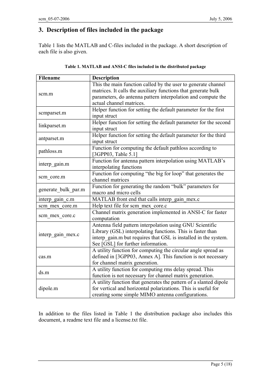
Table 1. MATLAB and ANSI-C files included in the distributed package
Filename
scm.m
scmparset.m
linkparset.m
antparset.m
pathloss.m
interp_gain.m
Description
This the main function called by the user to generate channel
matrices. It calls the auxiliary functions that generate bulk
parameters, do antenna pattern interpolation and compute the
actual channel matrices.
Helper function for setting the default parameter for the first
input struct
Helper function for setting the default parameter for the second
input struct
Helper function for setting the default parameter for the third
input struct
Function for computing the default pathloss according to
[3GPP03, Table 5.1]
Function for antenna pattern interpolation using MATLAB’s
interpolating functions
Function for computing “the big for loop” that generates the
channel matrices
scm_core.m
generate_bulk_par.m Function for generating the random “bulk” parameters for
interp_gain_c.m
scm_mex_core.m
scm_mex_core.c
macro and micro cells
MATLAB front end that calls interp_gain_mex.c
Help text file for scm_mex_core.c
Channel matrix generation implemented in ANSI-C for faster
computation
Antenna field pattern interpolation using GNU Scientific
Library (GSL) interpolating functions. This is faster than
interp_gain.m but requires that GSL is installed in the system.
See [GSL] for further information.
A utility function for computing the circular angle spread as
defined in [3GPP03, Annex A]. This function is not necessary
for channel matrix generation.
A utility function for computing rms delay spread. This
function is not necessary for channel matrix generation.
A utility function that generates the pattern of a slanted dipole
for vertical and horizontal polarizations. This is useful for
creating some simple MIMO antenna configurations.
interp_gain_mex.c
cas.m
ds.m
dipole.m
In addition to the files listed in Table 1 the distribution package also includes this
document, a readme text file and a license.txt file.
Page 5 (18)
�
July 5, 2006
scm_05-07-2006
4. Model input/output interface
The full syntax for the SCM function is ([ . ] indicates optional arguments):
[CHAN, [DELAYS], [FULLOUTPUT] ] = SCM( SCMPAR, LINKPAR, ANTPAR, [INITVALUES]).
Some quick comments:
• All input arguments are MATLAB structs. The first three input arguments are
mandatory. A helper function will be supplied so that their default values can be
set easily.
• The fourth input argument is optional. When given, SCM does not generate the
channel parameters randomly, but uses the user-supplied initial channel values.
• The first output argument is a 5D-array containing the MIMO channel matrices
for all links over a specified number of time samples.
• The second output argument includes multipath delays for all links. The path
delays are given in seconds.
• The third output argument is a MATLAB struct containing the randomly
generated link parameters and the final phases of the complex sinusoids. This
MATLAB struct can be used as INITVALUES in subsequent function calls.
The input and output parameters are explained in the following sections.
4.1 Input parameters
There are four input arguments, all of which are MATLAB structs. The first three
arguments are mandatory. Tables 1-4 describe the fields of the input structs.
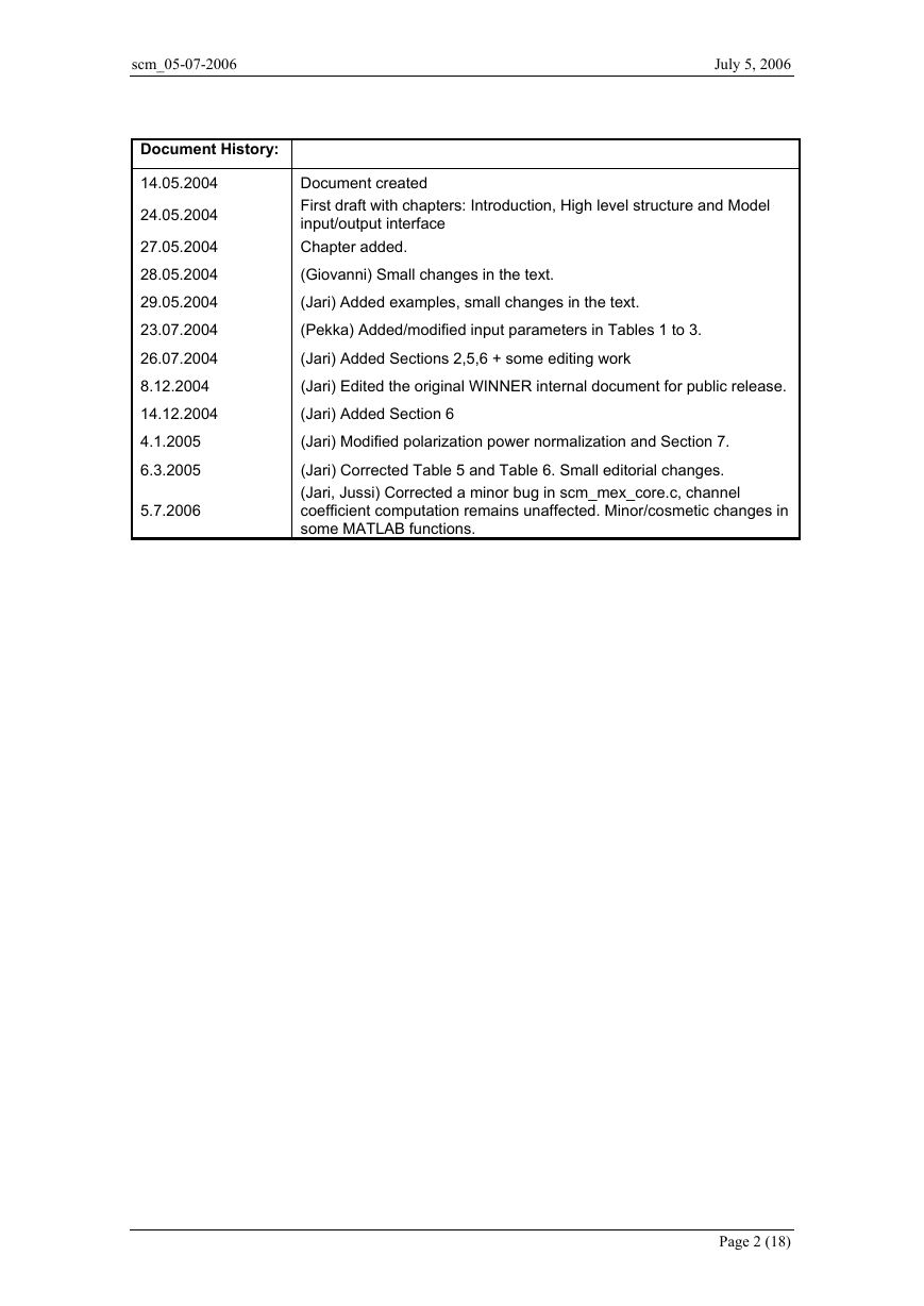
Table 2: General channel model parameters. Common for all links, MATLAB struct SCMPAR.
Parameter name
NumBsElements
NumMsElements
Scenario
SampleDensity
NumTimeSamples
UniformTimeSampling
Definition
The number of elements in the BS array. This
parameter is ignored if antenna patterns are defined
in the input struct ANTPAR. In this case the number
of BS elements is extracted from the antenna
definition.
The number of elements in the MS array. This
parameter is ignored if antenna patterns are defined
in the input struct ANTPAR. In this case the number
of BS elements is extracted from the antenna
definition.
Selected SCM channel,scenario (‘suburban_macro’,
‘urban_macro’ or ‘urban_micro’)
Time sampling interval of the channel. A value
greater than one should be selected if Doppler
analysis is to be done.
Number of channel samples (impulse response
matrices) to generate per link.
If this parameter has value ‘yes’, the time sampling
interval of the channel for each user will be equal.
Sampling interval will be calculated from the
SampleDensity and the highest velocity found in the
input parameter vector MsVelocity. If this
parameter has value ’no’, then the time sampling
interval for each link will be different, if MSs have
different speeds (see linkpar.MsVelocity). Setting
this parameters ‘yes’ may be useful in some system-
level simulations where all simulated links need to
be sampled at equal time intervals, regardless of MS
Default value
Unit
2
2
’urban_micro’
-
2
100
‘no’
samples/half
wavelength
-
Page 6 (18)
�
scm_05-07-2006
July 5, 2006
speeds.
BS mean angle spread for urban macro
environment. Possible values are ‘eight’ and
‘fifteen’ degrees. This variable is ignored if
‘Scenario’ is not ‘urban_macro’.
Number of paths (channel taps). Path delays are
drawn from the delay distribution specified in
[3GPP03] regardless of the number of paths set.
Number of sub-paths per path. The only value
supported in the SCM specification is 20 subpaths,
see [3GPP03, Table 5.2].
Carrier center frequency. Affects path loss and time
sampling interval.
SCM options
('none','polarized','los','urban_canyon'). The options
are mutually exclusive.
Delay sampling interval (delay resolution). The
default corresponds to Tc/16, where Tc=1/3.84e6
[3GPP03, Sec. 5.3.1].
With this set to ‘yes’ the power of the elements of
the channel matrix (without pathloss) is normalized
to a constant, that does not depend on the XPD
ratios. See Section 6.2.
Path loss included in the channel matrices yes/no (if
‘no’, PL is calculated and returned in the third
output argument, but not multiplied with the
channel matrices)
Shadow fading included in the channel matrices
yes/no (if ‘no’ shadow fading is still computed and
returned in the third output argument, but not
multiplied with the channel matrices). Note that if
both path loss and shadowing are switched off the
average power of the channel matrix elements will
be one (with azimuthally uniform unit gain
antennas).
The name of the path loss function. Function
‘pathloss’ implements the default SCM path loss
model. If the default is used, center frequency is
taken from the parameter CenterFrequency. One can
define his/her own path loss function. For syntax,
see PATHLOSS.
Use optimized computation yes/no. With ‘yes’
faster C-function is used instead of m-function.
Note the C-function SCM_MEX_CORE.C must be
compiled before usage. For more information, see
SCM_MEX_CORE.M.
If optimized computation is used, complex
exponentials are taken from a look-up table to speed
up computation or calculated explicitly. This
parameter defines the lookup table size. Value 0
indicates that lookup table is not used, value –1 uses
the default table size 214 =16384. The size of the
table must be a power-of-two. If AnsiC_core = ‘no’
this parameter is ignored.
Random seed for fully repeatable channel
generation (if empty, seed is generated randomly).
Note that even if RandomSeed is fixed, two channel
realizations may still not be the same due to
potential differences between random number
generators in different MATLAB versions. Note
also that one must also use the same link and
antenna parameters.
BsUrbanMacroAS
NumPaths
NumSubPathsPerPath
CenterFrequency
ScmOptions
DelaySamplingInterval
XpdIndependentPower
PathLossModelUsed
ShadowingModelUsed
PathLossModel
AnsiC_core
LookUpTable
RandomSeed
‘eight’
6
20
2E9
‘none’
1.6276e-8
‘no’
‘no’
‘no’
‘pathloss’
‘no’
-
-
-
Hz
-
sec
-
-
-
-
-
0
integer
integer
Page 7 (18)
�
scm_05-07-2006
July 5, 2006
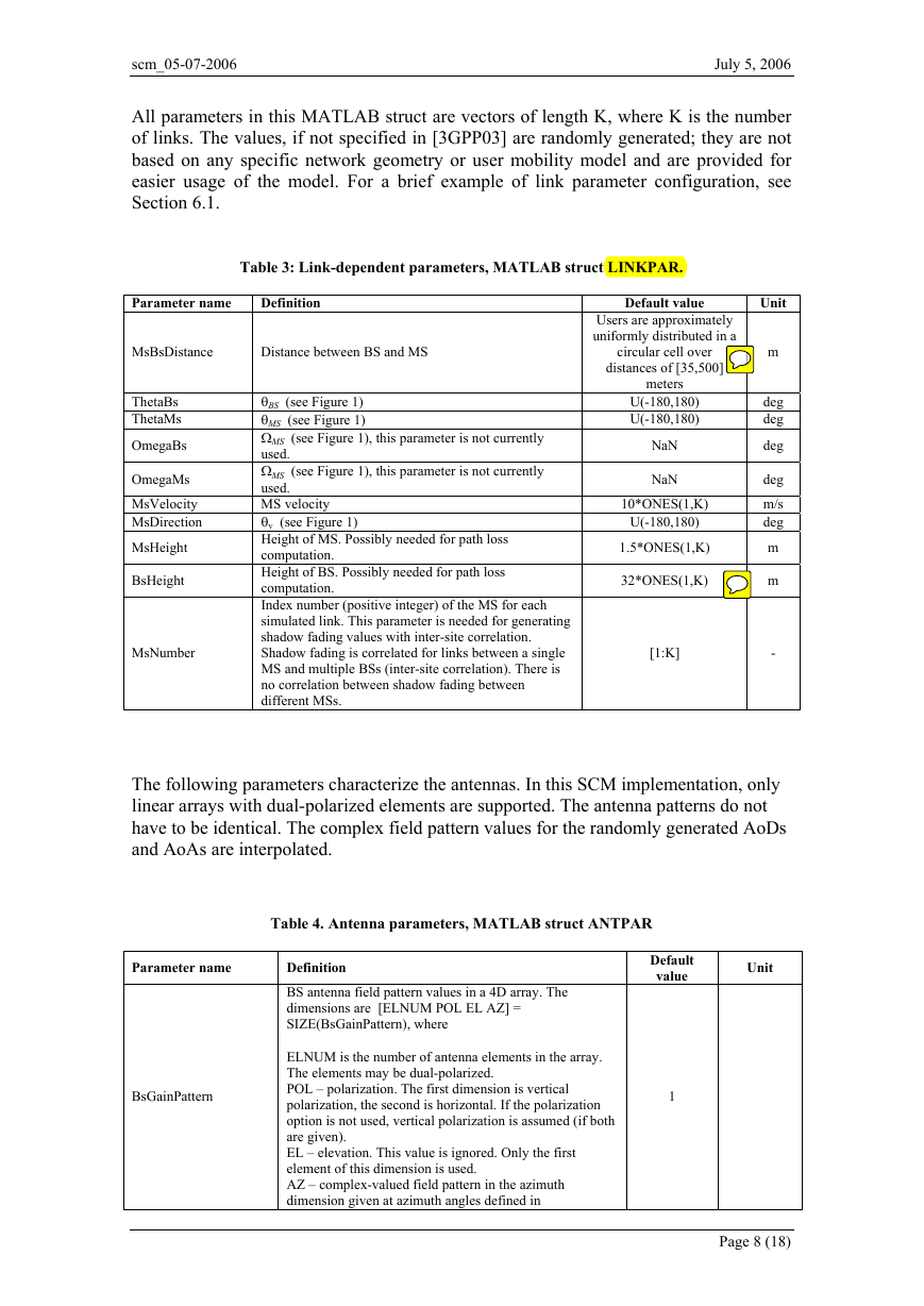
All parameters in this MATLAB struct are vectors of length K, where K is the number
of links. The values, if not specified in [3GPP03] are randomly generated; they are not
based on any specific network geometry or user mobility model and are provided for
easier usage of the model. For a brief example of link parameter configuration, see
Section 6.1.
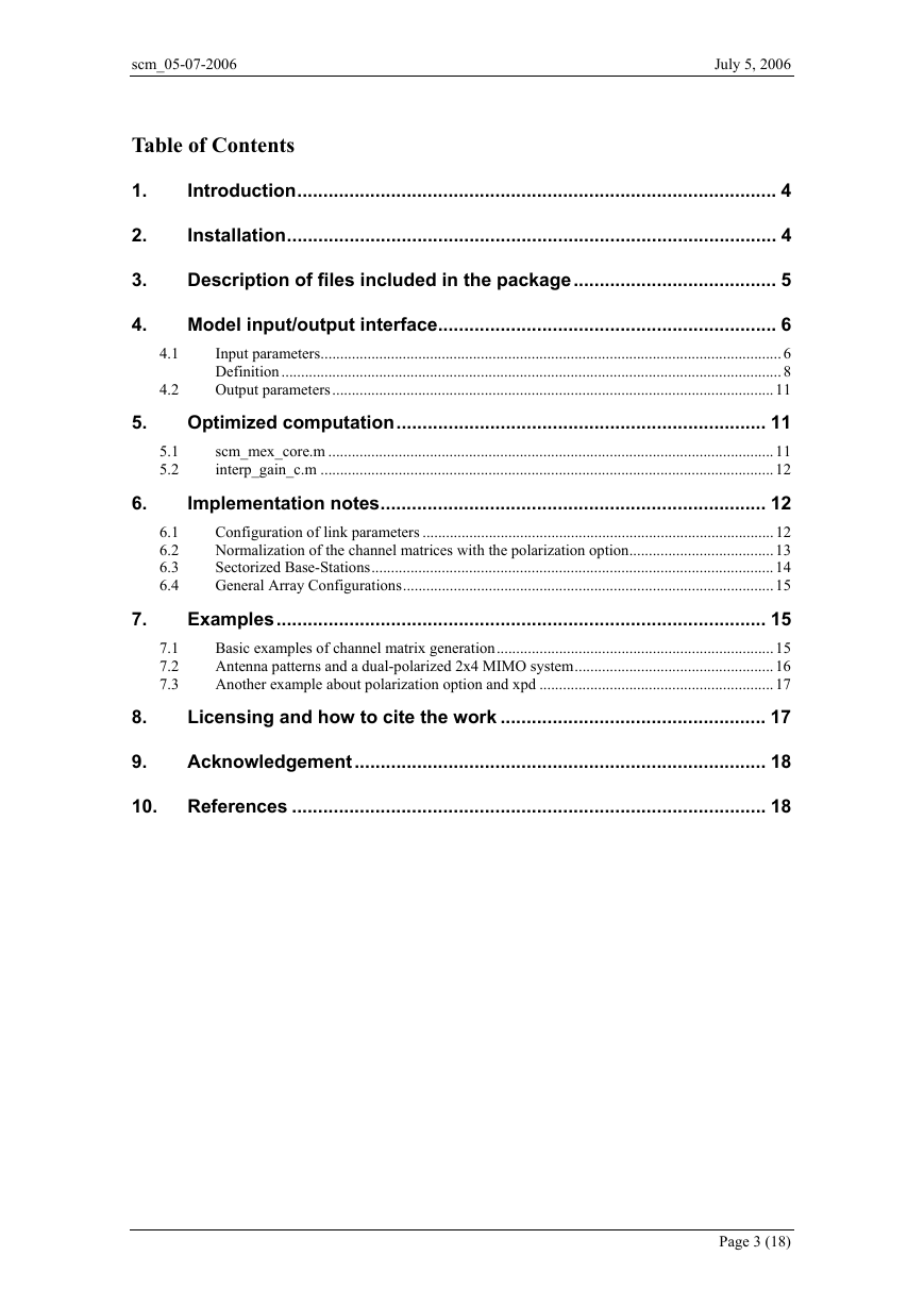
Table 3: Link-dependent parameters, MATLAB struct LINKPAR.
Parameter name
Definition
MsBsDistance
Distance between BS and MS
ThetaBs
ThetaMs
OmegaBs
OmegaMs
MsVelocity
MsDirection
MsHeight
BsHeight
MsNumber
θBS (see Figure 1)
θMS (see Figure 1)
ΩMS (see Figure 1), this parameter is not currently
used.
ΩMS (see Figure 1), this parameter is not currently
used.
MS velocity
θv (see Figure 1)
Height of MS. Possibly needed for path loss
computation.
Height of BS. Possibly needed for path loss
computation.
Index number (positive integer) of the MS for each
simulated link. This parameter is needed for generating
shadow fading values with inter-site correlation.
Shadow fading is correlated for links between a single
MS and multiple BSs (inter-site correlation). There is
no correlation between shadow fading between
different MSs.
Default value
Users are approximately
uniformly distributed in a
circular cell over
distances of [35,500]
meters
U(-180,180)
U(-180,180)
NaN
NaN
10*ONES(1,K)
U(-180,180)
1.5*ONES(1,K)
32*ONES(1,K)
[1:K]
Unit
m
deg
deg
deg
deg
m/s
deg
m
m
-
The following parameters characterize the antennas. In this SCM implementation, only
linear arrays with dual-polarized elements are supported. The antenna patterns do not
have to be identical. The complex field pattern values for the randomly generated AoDs
and AoAs are interpolated.
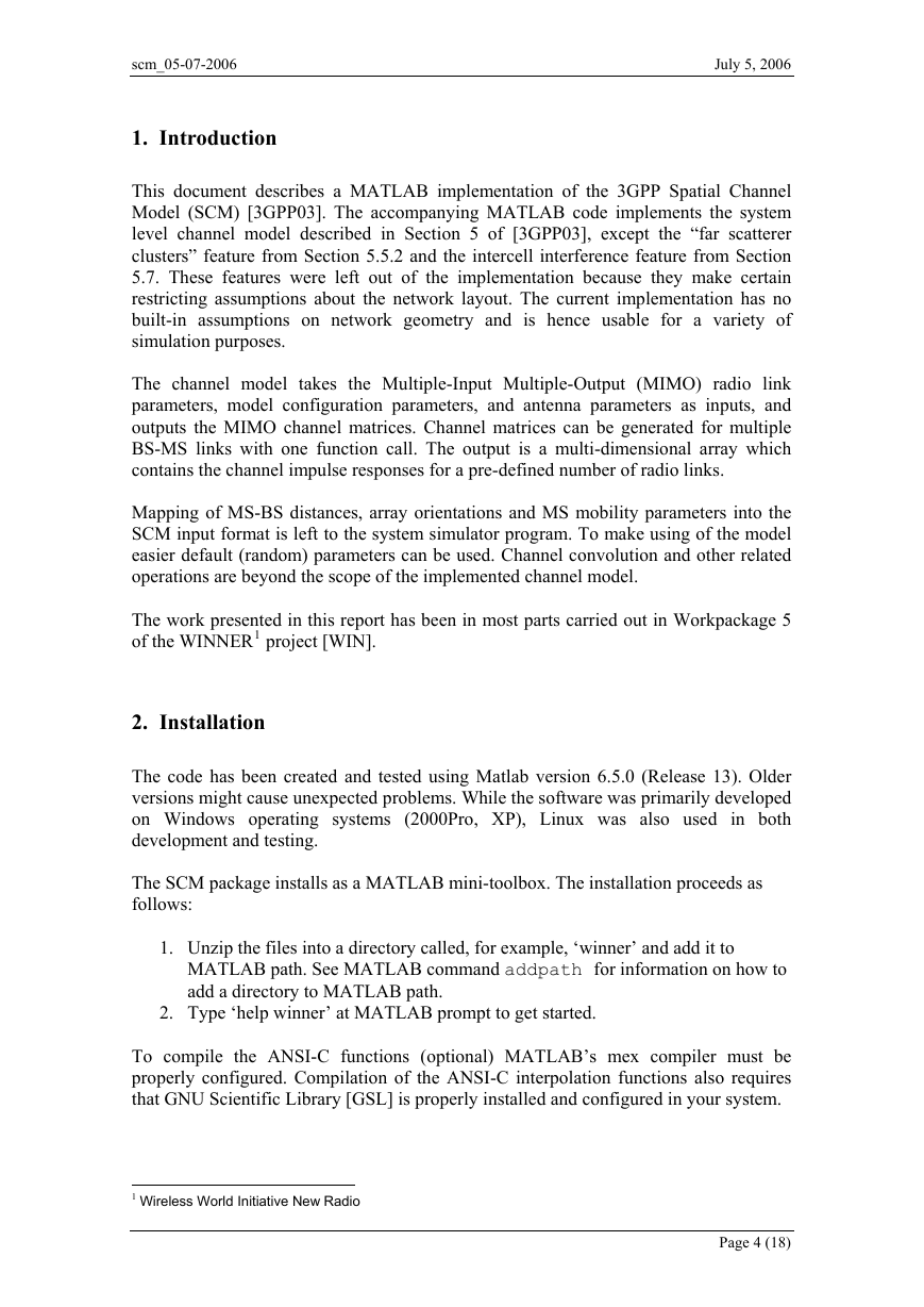
Table 4. Antenna parameters, MATLAB struct ANTPAR
Parameter name
BsGainPattern
Definition
BS antenna field pattern values in a 4D array. The
dimensions are [ELNUM POL EL AZ] =
SIZE(BsGainPattern), where
ELNUM is the number of antenna elements in the array.
The elements may be dual-polarized.
POL – polarization. The first dimension is vertical
polarization, the second is horizontal. If the polarization
option is not used, vertical polarization is assumed (if both
are given).
EL – elevation. This value is ignored. Only the first
element of this dimension is used.
AZ – complex-valued field pattern in the azimuth
dimension given at azimuth angles defined in
Default
value
Unit
1
Page 8 (18)
�





 2023年江西萍乡中考道德与法治真题及答案.doc
 2012年重庆南川中考生物真题及答案.doc
 2013年江西师范大学地理学综合及文艺理论基础考研真题.doc
 2020年四川甘孜小升初语文真题及答案I卷.doc
 2020年注册岩土工程师专业基础考试真题及答案.doc
 2023-2024学年福建省厦门市九年级上学期数学月考试题及答案.doc
 2021-2022学年辽宁省沈阳市大东区九年级上学期语文期末试题及答案.doc
 2022-2023学年北京东城区初三第一学期物理期末试卷及答案.doc
 2018上半年江西教师资格初中地理学科知识与教学能力真题及答案.doc
 2012年河北国家公务员申论考试真题及答案-省级.doc
 2020-2021学年江苏省扬州市江都区邵樊片九年级上学期数学第一次质量检测试题及答案.doc
 2022下半年黑龙江教师资格证中学综合素质真题及答案.doc