logo资料库

BCM5396 BCM5389 BCM5387设计手册.pdf

第1页 / 共68页
第2页 / 共68页
第3页 / 共68页
第4页 / 共68页
第5页 / 共68页
第6页 / 共68页
第7页 / 共68页
第8页 / 共68页
资料共68页,剩余部分请下载后查看
BCM538X/BCM5396 Application Note
Revision History
Table of Contents
List of Figures
List of Tables
Section 1: Overview
Eight-Port Stand-Alone Switch
System Interfaces
Sample Applications
Section 2: Selected Design Recommendations
PCB Stackup
Component Placement
Decoupling/Bypassing
Magnetics
Routing
L0 Plane Stitching with Vias
Section 3: MAC and Media Interfaces
SGMII Interface
Configuring SGMII Mode
Pin Descriptions
SGMII Receive
SGMII Transmit
Auto-negotiation and Control Information Exchanged Between Links
SGMII Layout
SerDes Interface
Configuring SerDes Mode
Pin Descriptions
SerDes Receive
SerDes Transmit
Auto-negotiation and Control Information Exchanged Between Links
Connecting SerDes to Fiber Module
SerDes to Backplane/Cable Interface
SerDes/SGMII Layout Guidelines
RvMII Interface
3.3V MII I/Os
Pin Descriptions
Transmit RvMII
Receive RvMII
RvMII Driver Compliance
RvMII Layout
GMII Interface
3.3V GMII I/Os
Pin Descriptions
Transmit GMII
Receive GMII
GMII Driver Compliance
GMII Layout
RGMII Interface
Signal Descriptions
Pin Descriptions
RGMII Transmit
RGMII Receive
RGMII Delayed Timing
Delayed Transmit Timing
Delayed Receive Timing
Data and Control Signal Encoding
RGMII Layout
Section 4: I/O Pins
1.2V/2.5V with 3.3V Tolerance
Internal Pull-Ups and Pull-Downs
Configuring the Programming Interfaces
Reset
Unused Pins
Section 5: Programming Interfaces
SPI Compatible Programming Interface
External PHY Registers
Clock Polarity and Phase
Read and Write Examples
Normal Mode Read
Fast Mode Read
Normal Mode Write
EEPROM Interface Connection
MDC/MDIO Interface
Master: External PHY Registers
Internal SerDes Transceiver and Pseudo PHY
BCM5396 Dual MDC/MDIO
Section 6: Power Considerations
Supply Voltages
Core and I/O Power Sequencing Requirements
IR Drops
Input Voltage and Noise Tolerance
Design Considerations for Main Power Supply
Power Supply Filter Components Recommendations
General Guidelines
Power and Ground Planes
Decoupling Capacitors
Bulk Filter Capacitors
Ferrite Bead
Specific Power Supply Decoupling Recommendations for the BCM5389 and BCM5387
PLLAVDD, PLLAVDD2
SAVDD
DVDD
PLLDVDD
OVDD
OVDD2
XTALVDD
Specific Power Supply Decoupling Recommendations for the BCM5396
PLLAVDD1, PLLAVDD2
TXVDD
VDDC
PLLDVDD3,PLLDVDD4
VDDO33
VDDO25
XTALVDD1, XTALVDD2
VDDP
Section 7: Clock Design Considerations
Reference Clock
Peak-to-Peak Clock Jitter Measurement
Section 8: LED Considerations
BCM5389/BCM5387 Parallel LEDs
BCM538X/BCM5396 Serial LEDs
LNKG/ACTF and LNKF/ACTG LEDS Used in Pairs
Section 9: Thermal Information
Thermal Information
BCM5396 Thermal Characteristics
BCM5389/BCM5387 Thermal Characteristics
Application Note BCM538X/BCM5396 BCM5396 and BCM5389/BCM5387 Design Guidelines 5300 California Avenue • Irvine, CA 92617 • Phone: 949-926-5000 • Fax: 949-926-5203 538X_5396-AN105-R January 20, 2010
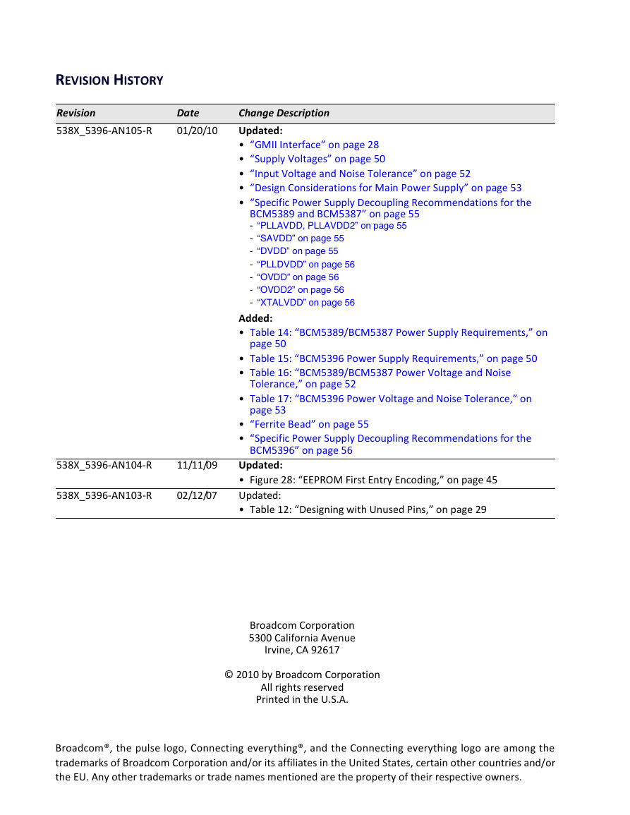
REVISION HISTORY Revision 538X_5396-AN105-R Date 01/20/10 538X_5396-AN104-R 11/11/09 538X_5396-AN103-R 02/12/07 Change Description Updated: • “GMII Interface” on page 28 • “Supply Voltages” on page 50 • “Input Voltage and Noise Tolerance” on page 52 • “Design Considerations for Main Power Supply” on page 53 • “Specific Power Supply Decoupling Recommendations for the BCM5389 and BCM5387” on page 55 - “PLLAVDD, PLLAVDD2” on page 55 - “SAVDD” on page 55 - “DVDD” on page 55 - “PLLDVDD” on page 56 - “OVDD” on page 56 - “OVDD2” on page 56 - “XTALVDD” on page 56 Added: • Table 14: “BCM5389/BCM5387 Power Supply Requirements,” on page 50 • Table 15: “BCM5396 Power Supply Requirements,” on page 50 • Table 16: “BCM5389/BCM5387 Power Voltage and Noise Tolerance,” on page 52 • Table 17: “BCM5396 Power Voltage and Noise Tolerance,” on page 53 • “Ferrite Bead” on page 55 • “Specific Power Supply Decoupling Recommendations for the BCM5396” on page 56 Updated: • Figure 28: “EEPROM First Entry Encoding,” on page 45 Updated: • Table 12: “Designing with Unused Pins,” on page 29 Broadcom Corporation 5300 California Avenue Irvine, CA 92617 © 2010 by Broadcom Corporation All rights reserved Printed in the U.S.A. Broadcom®, the pulse logo, Connecting everything®, and the Connecting everything logo are among the trademarks of Broadcom Corporation and/or its affiliates in the United States, certain other countries and/or the EU. Any other trademarks or trade names mentioned are the property of their respective owners.
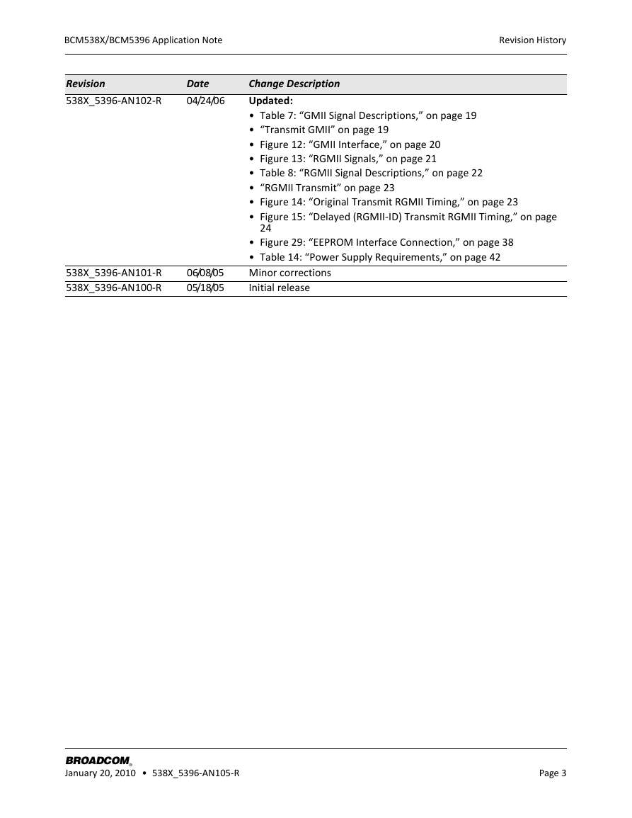
BCM538X/BCM5396 Application Note Revision History Revision 538X_5396-AN102-R Date 04/24/06 538X_5396-AN101-R 538X_5396-AN100-R 06/08/05 05/18/05 Change Description Updated: • Table 7: “GMII Signal Descriptions,” on page 19 • “Transmit GMII” on page 19 • Figure 12: “GMII Interface,” on page 20 • Figure 13: “RGMII Signals,” on page 21 • Table 8: “RGMII Signal Descriptions,” on page 22 • “RGMII Transmit” on page 23 • Figure 14: “Original Transmit RGMII Timing,” on page 23 • Figure 15: “Delayed (RGMII-ID) Transmit RGMII Timing,” on page 24 • Figure 29: “EEPROM Interface Connection,” on page 38 • Table 14: “Power Supply Requirements,” on page 42 Minor corrections Initial release BROADCOM January 20, 2010 • 538X_5396-AN105-R ® Page 3
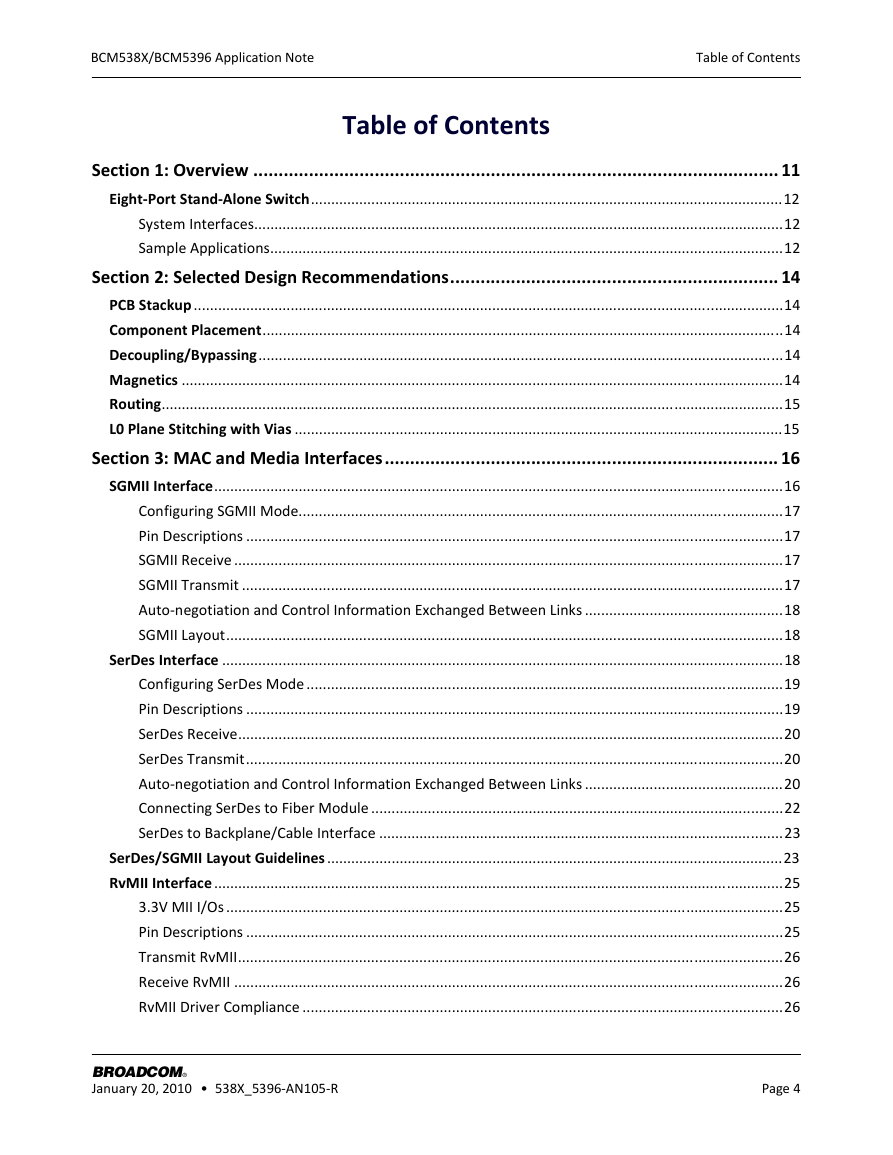
BCM538X/BCM5396 Application Note Table of Contents Table of Contents Section 1: Overview ........................................................................................................ 11 Eight-Port Stand-Alone Switch.....................................................................................................................12 System Interfaces...................................................................................................................................12 Sample Applications...............................................................................................................................12 Section 2: Selected Design Recommendations................................................................. 14 PCB Stackup ..................................................................................................................................................14 Component Placement.................................................................................................................................14 Decoupling/Bypassing..................................................................................................................................14 Magnetics .....................................................................................................................................................14 Routing..........................................................................................................................................................15 L0 Plane Stitching with Vias .........................................................................................................................15 Section 3: MAC and Media Interfaces.............................................................................. 16 SGMII Interface.............................................................................................................................................16 Configuring SGMII Mode........................................................................................................................17 Pin Descriptions .....................................................................................................................................17 SGMII Receive ........................................................................................................................................17 SGMII Transmit ......................................................................................................................................17 Auto-negotiation and Control Information Exchanged Between Links .................................................18 SGMII Layout..........................................................................................................................................18 SerDes Interface ...........................................................................................................................................18 Configuring SerDes Mode ......................................................................................................................19 Pin Descriptions .....................................................................................................................................19 SerDes Receive.......................................................................................................................................20 SerDes Transmit.....................................................................................................................................20 Auto-negotiation and Control Information Exchanged Between Links .................................................20 Connecting SerDes to Fiber Module ......................................................................................................22 SerDes to Backplane/Cable Interface ....................................................................................................23 SerDes/SGMII Layout Guidelines .................................................................................................................23 RvMII Interface .............................................................................................................................................25 3.3V MII I/Os ..........................................................................................................................................25 Pin Descriptions .....................................................................................................................................25 Transmit RvMII.......................................................................................................................................26 Receive RvMII ........................................................................................................................................26 RvMII Driver Compliance .......................................................................................................................26 BROADCOM January 20, 2010 • 538X_5396-AN105-R ® Page 4
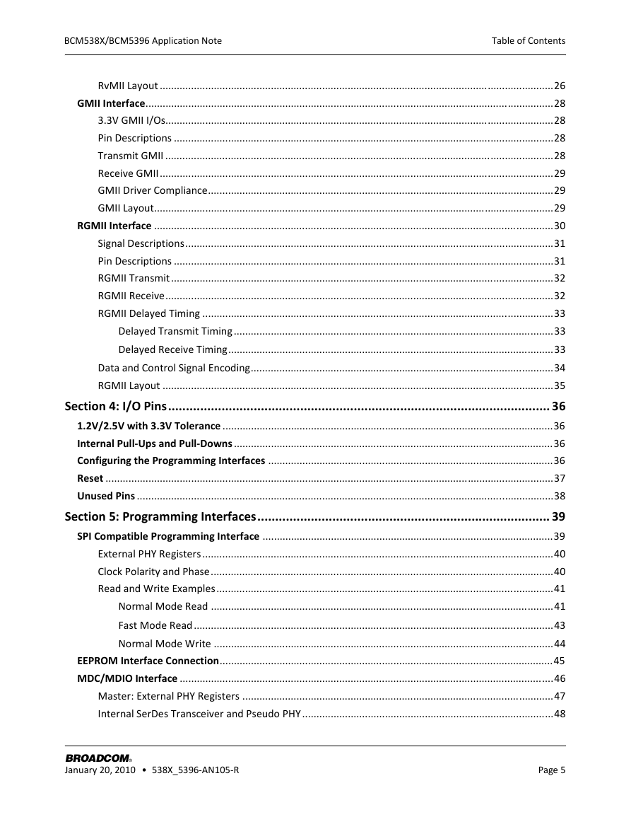
BCM538X/BCM5396 Application Note Table of Contents RvMII Layout ..........................................................................................................................................26 GMII Interface...............................................................................................................................................28 3.3V GMII I/Os........................................................................................................................................28 Pin Descriptions .....................................................................................................................................28 Transmit GMII ........................................................................................................................................28 Receive GMII..........................................................................................................................................29 GMII Driver Compliance.........................................................................................................................29 GMII Layout............................................................................................................................................29 RGMII Interface ............................................................................................................................................30 Signal Descriptions.................................................................................................................................31 Pin Descriptions .....................................................................................................................................31 RGMII Transmit......................................................................................................................................32 RGMII Receive........................................................................................................................................32 RGMII Delayed Timing ...........................................................................................................................33 Delayed Transmit Timing................................................................................................................33 Delayed Receive Timing..................................................................................................................33 Data and Control Signal Encoding..........................................................................................................34 RGMII Layout .........................................................................................................................................35 Section 4: I/O Pins........................................................................................................... 36 1.2V/2.5V with 3.3V Tolerance ....................................................................................................................36 Internal Pull-Ups and Pull-Downs ................................................................................................................36 Configuring the Programming Interfaces ....................................................................................................36 Reset .............................................................................................................................................................37 Unused Pins ..................................................................................................................................................38 Section 5: Programming Interfaces.................................................................................. 39 SPI Compatible Programming Interface ......................................................................................................39 External PHY Registers...........................................................................................................................40 Clock Polarity and Phase........................................................................................................................40 Read and Write Examples......................................................................................................................41 Normal Mode Read ........................................................................................................................41 Fast Mode Read..............................................................................................................................43 Normal Mode Write .......................................................................................................................44 EEPROM Interface Connection.....................................................................................................................45 MDC/MDIO Interface ...................................................................................................................................46 Master: External PHY Registers .............................................................................................................47 Internal SerDes Transceiver and Pseudo PHY........................................................................................48 BROADCOM January 20, 2010 • 538X_5396-AN105-R ® Page 5
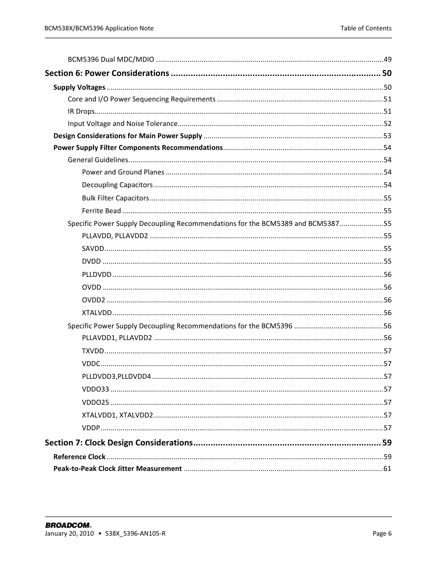
BCM538X/BCM5396 Application Note Table of Contents BCM5396 Dual MDC/MDIO ...................................................................................................................49 Section 6: Power Considerations ..................................................................................... 50 Supply Voltages ............................................................................................................................................50 Core and I/O Power Sequencing Requirements ....................................................................................51 IR Drops..................................................................................................................................................51 Input Voltage and Noise Tolerance........................................................................................................52 Design Considerations for Main Power Supply ...........................................................................................53 Power Supply Filter Components Recommendations.................................................................................54 General Guidelines.................................................................................................................................54 Power and Ground Planes ..............................................................................................................54 Decoupling Capacitors ....................................................................................................................54 Bulk Filter Capacitors......................................................................................................................55 Ferrite Bead ....................................................................................................................................55 Specific Power Supply Decoupling Recommendations for the BCM5389 and BCM5387......................55 PLLAVDD, PLLAVDD2 ......................................................................................................................55 SAVDD.............................................................................................................................................55 DVDD ..............................................................................................................................................55 PLLDVDD .........................................................................................................................................56 OVDD ..............................................................................................................................................56 OVDD2 ............................................................................................................................................56 XTALVDD.........................................................................................................................................56 Specific Power Supply Decoupling Recommendations for the BCM5396 .............................................56 PLLAVDD1, PLLAVDD2 ....................................................................................................................56 TXVDD.............................................................................................................................................57 VDDC...............................................................................................................................................57 PLLDVDD3,PLLDVDD4 .....................................................................................................................57 VDDO33 ..........................................................................................................................................57 VDDO25 ..........................................................................................................................................57 XTALVDD1, XTALVDD2....................................................................................................................57 VDDP...............................................................................................................................................57 Section 7: Clock Design Considerations............................................................................ 59 Reference Clock ............................................................................................................................................59 Peak-to-Peak Clock Jitter Measurement .....................................................................................................61 BROADCOM January 20, 2010 • 538X_5396-AN105-R ® Page 6
BCM538X/BCM5396 Application Note Table of Contents Section 8: LED Considerations ......................................................................................... 63 BCM5389/BCM5387 Parallel LEDs ...............................................................................................................63 BCM538X/BCM5396 Serial LEDs ..................................................................................................................64 LNKG/ACTF and LNKF/ACTG LEDS Used in Pairs....................................................................................65 Section 9: Thermal Information....................................................................................... 66 Thermal Information ....................................................................................................................................66 BCM5396 Thermal Characteristics.........................................................................................................66 BCM5389/BCM5387 Thermal Characteristics .......................................................................................66 BROADCOM January 20, 2010 • 538X_5396-AN105-R ® Page 7
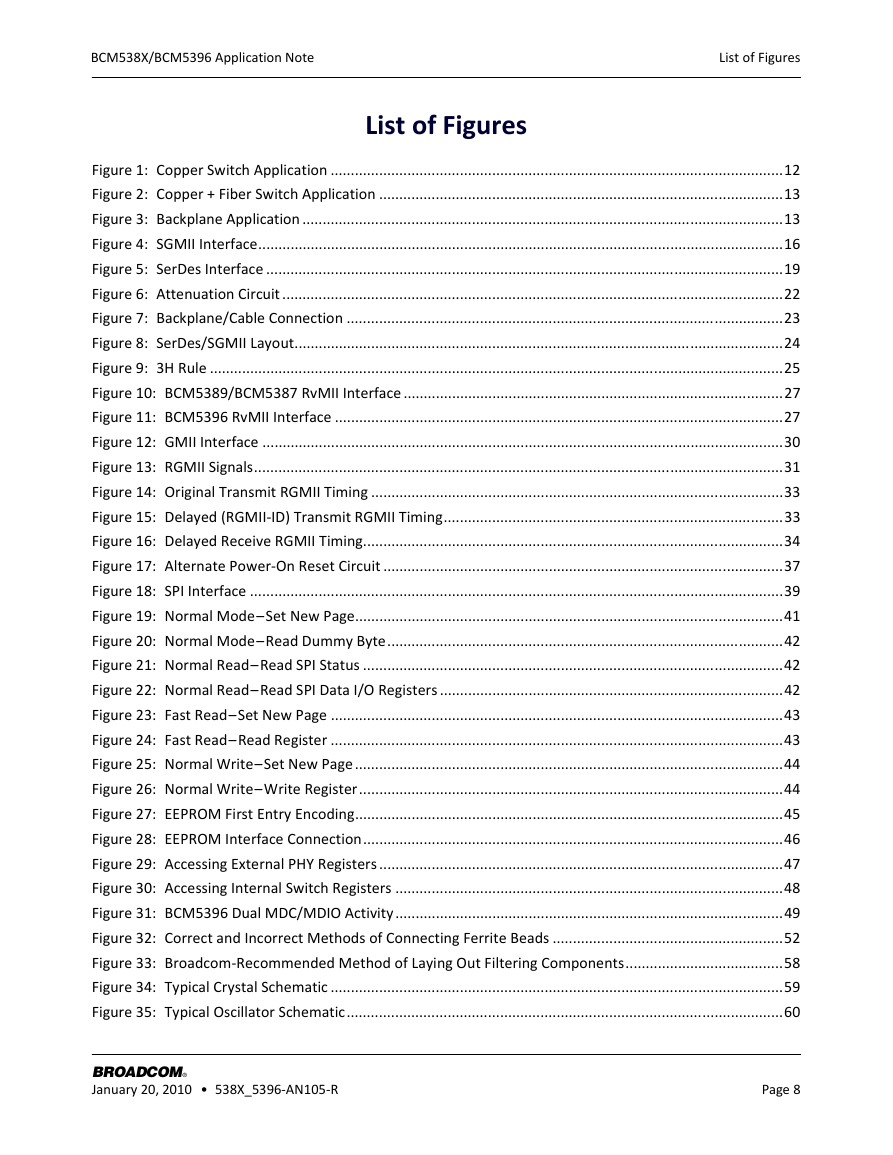
BCM538X/BCM5396 Application Note List of Figures List of Figures Figure 1: Copper Switch Application ................................................................................................................12 Figure 2: Copper + Fiber Switch Application ....................................................................................................13 Figure 3: Backplane Application .......................................................................................................................13 Figure 4: SGMII Interface..................................................................................................................................16 Figure 5: SerDes Interface ................................................................................................................................19 Figure 6: Attenuation Circuit ............................................................................................................................22 Figure 7: Backplane/Cable Connection ............................................................................................................23 Figure 8: SerDes/SGMII Layout.........................................................................................................................24 Figure 9: 3H Rule ..............................................................................................................................................25 Figure 10: BCM5389/BCM5387 RvMII Interface ..............................................................................................27 Figure 11: BCM5396 RvMII Interface ...............................................................................................................27 Figure 12: GMII Interface .................................................................................................................................30 Figure 13: RGMII Signals...................................................................................................................................31 Figure 14: Original Transmit RGMII Timing ......................................................................................................33 Figure 15: Delayed (RGMII-ID) Transmit RGMII Timing....................................................................................33 Figure 16: Delayed Receive RGMII Timing........................................................................................................34 Figure 17: Alternate Power-On Reset Circuit ...................................................................................................37 Figure 18: SPI Interface ....................................................................................................................................39 Figure 19: Normal Mode – Set New Page..........................................................................................................41 Figure 20: Normal Mode – Read Dummy Byte..................................................................................................42 Figure 21: Normal Read – Read SPI Status ........................................................................................................42 Figure 22: Normal Read – Read SPI Data I/O Registers .....................................................................................42 Figure 23: Fast Read – Set New Page ................................................................................................................43 Figure 24: Fast Read – Read Register ................................................................................................................43 Figure 25: Normal Write – Set New Page ..........................................................................................................44 Figure 26: Normal Write – Write Register.........................................................................................................44 Figure 27: EEPROM First Entry Encoding..........................................................................................................45 Figure 28: EEPROM Interface Connection........................................................................................................46 Figure 29: Accessing External PHY Registers ....................................................................................................47 Figure 30: Accessing Internal Switch Registers ................................................................................................48 Figure 31: BCM5396 Dual MDC/MDIO Activity ................................................................................................49 Figure 32: Correct and Incorrect Methods of Connecting Ferrite Beads .........................................................52 Figure 33: Broadcom-Recommended Method of Laying Out Filtering Components.......................................58 Figure 34: Typical Crystal Schematic ................................................................................................................59 Figure 35: Typical Oscillator Schematic............................................................................................................60 BROADCOM January 20, 2010 • 538X_5396-AN105-R ® Page 8
分享到:
收藏