LM2596
General Description
Features
Applications
Typical Application
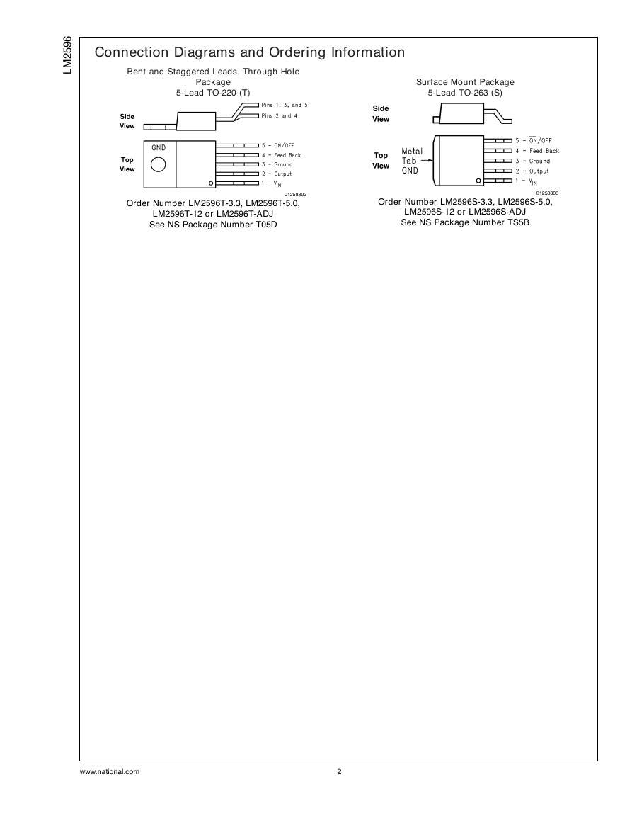
Connection Diagrams and Ordering Information
Absolute Maximum Ratings
Operating Conditions
LM2596-3.3 Electrical Characteristics
LM2596-5.0 Electrical Characteristics
LM2596-12 Electrical Characteristics
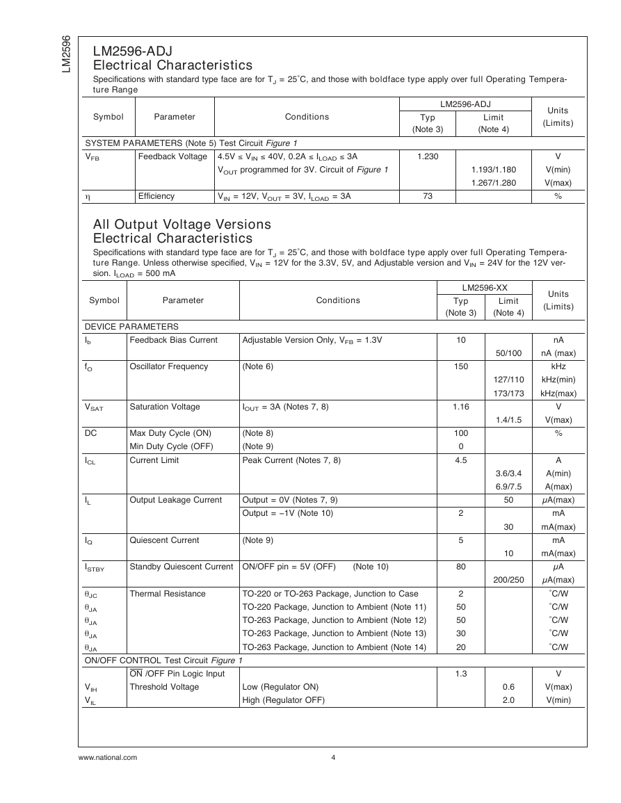
LM2596-ADJ Electrical Characteristics
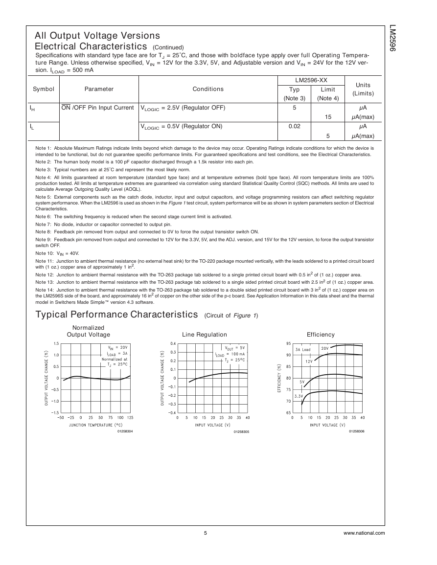
All Output Voltage Versions Electrical Characteristics
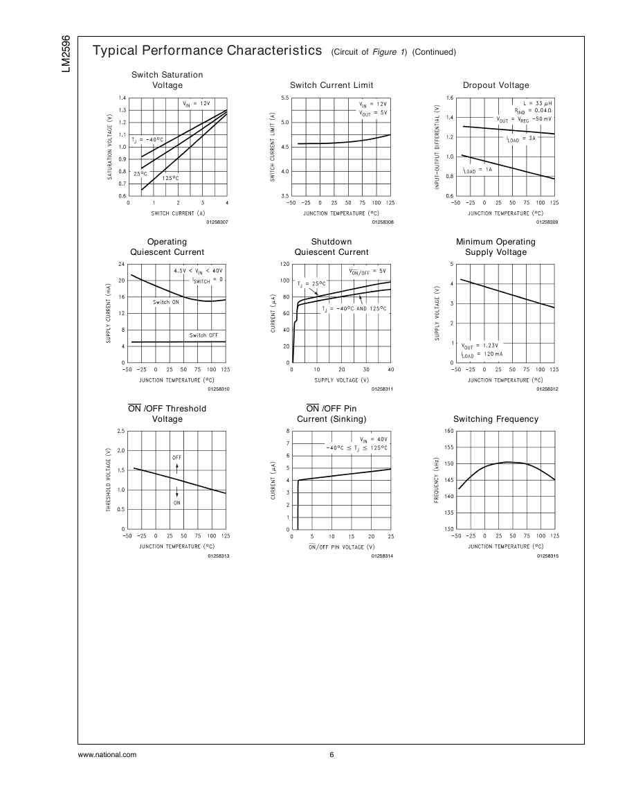
Typical Performance Characteristics
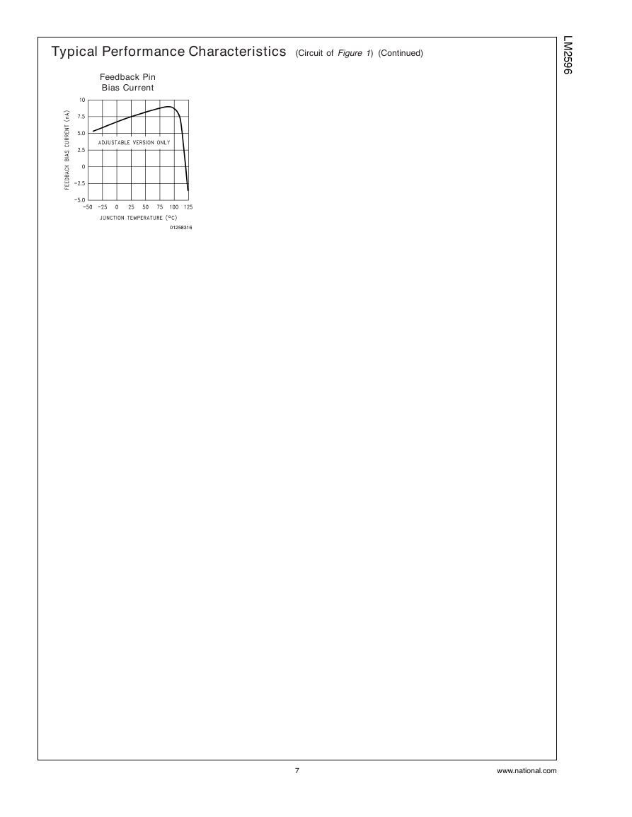
Typical Performance Characteristics
Test Circuit and Layout Guidelines
FIGURE 1. Standard Test Circuits and Layout Guides
LM2596 Series Buck Regulator Design Procedure (Fixed Output)
FIGURE 2. LM2596 Fixed Voltage Quick Design Component Selection Table
LM2596 Series Buck Regulator Design Procedure (Adjustable Output)
LM2596 Series Buck Regulator Design Procedure (Adjustable Output)
FIGURE 3. Output Capacitor and Feedforward Capacitor Selection Table
LM2596 Series Buck Regulator Design Procedure
INDUCTOR VALUE SELECTION GUIDES
FIGURE 4. LM2596-3.3
FIGURE 5. LM2596-5.0
FIGURE 6. LM2596-12
FIGURE 7. LM2596-ADJ
FIGURE 8. Inductor Manufacturers Part Numbers
FIGURE 9. Inductor Manufacturers Phone Numbers
FIGURE 10. Capacitor Manufacturers Phone Numbers
FIGURE 11. Diode Selection Table
FIGURE 12.
Application Information
PIN FUNCTIONS
EXTERNAL COMPONENTS
FEEDFORWARD CAPACITOR (Adjustable Output Voltage Version)
FIGURE 13. RMS Current Ratings for Low ESR Electrolytic Capacitors (Typical)
OUTPUT CAPACITOR
FIGURE 14. Capacitor ESR vs Capacitor Voltage Rating (Typical Low ESR Electrolytic Capacitor)
CATCH DIODE
FIGURE 15. Capacitor ESR Change vs Temperature
INDUCTOR SELECTION
FIGURE 16. (IIND) Peak-to-Peak Inductor Ripple Current (as a Percentage of the Load Current) vs
DISCONTINUOUS MODE OPERATION
FIGURE 17. Post Ripple Filter Waveform
OUTPUT VOLTAGE RIPPLE AND TRANSIENTS
FIGURE 18. Peak-to-Peak Inductor Ripple Current vs Load Current
OPEN CORE INDUCTORS
THERMAL CONSIDERATIONS
FIGURE 19. Junction Temperature Rise, TO-220
FIGURE 20. Junction Temperature Rise, TO-263
FIGURE 21. Delayed Startup
FIGURE 22. Undervoltage Lockout for Buck Regulator
DELAYED STARTUP
UNDERVOLTAGE LOCKOUT
INVERTING REGULATOR
FIGURE 23. Undervoltage Lockout for Inverting Regulator
FIGURE 24. Undervoltage Lockout with Hysteresis for Inverting Regulator
FIGURE 25. Inverting -5V Regulator with Delayed Startup
FIGURE 26. Inverting Regulator Typical Load Current
INVERTING REGULATOR SHUTDOWN METHODS
FIGURE 27. Inverting Regulator Ground Referenced Shutdown
FIGURE 28. Inverting Regulator Ground Referenced Shutdown using Opto Device
TYPICAL THROUGH HOLE PC BOARD LAYOUT, FIXED OUTPUT (1X SIZE), DOUBLE SIDED
TYPICAL THROUGH HOLE PC BOARD LAYOUT, ADJUSTABLE OUTPUT (1X SIZE), DOUBLE SIDED
FIGURE 29. PC Board Layout
Physical Dimensions




 2023年江西萍乡中考道德与法治真题及答案.doc
 2012年重庆南川中考生物真题及答案.doc
 2013年江西师范大学地理学综合及文艺理论基础考研真题.doc
 2020年四川甘孜小升初语文真题及答案I卷.doc
 2020年注册岩土工程师专业基础考试真题及答案.doc
 2023-2024学年福建省厦门市九年级上学期数学月考试题及答案.doc
 2021-2022学年辽宁省沈阳市大东区九年级上学期语文期末试题及答案.doc
 2022-2023学年北京东城区初三第一学期物理期末试卷及答案.doc
 2018上半年江西教师资格初中地理学科知识与教学能力真题及答案.doc
 2012年河北国家公务员申论考试真题及答案-省级.doc
 2020-2021学年江苏省扬州市江都区邵樊片九年级上学期数学第一次质量检测试题及答案.doc
 2022下半年黑龙江教师资格证中学综合素质真题及答案.doc