Chapter 3
Interpolator
The interpolator plays the role of generator of axis movement data from the block
data generated by the interpreter and is one of the key components of CNC, reflecting
its accuracy. In this chapter, the various software interpolators will be introduced and
their strengths and weaknesses will be described. In addition, a NURBS interpolator,
which is an advanced interpolation method, will be described and the implementation
algorithm will be introduced.
3.1 Introduction
A CNC machine generally has more than two controlled axes to machine complex
shapes. Two kinds of control can be carried out: The point-to-point control method
is used to move the axis to the desired position; and the contour control method is
used to move the axis along an arbitrary curve.
In order to execute these control methods successfully, tool movement should be
divided into components corresponding to each axis; the locus of the tool is created
through combining the individual displacements for each axis.
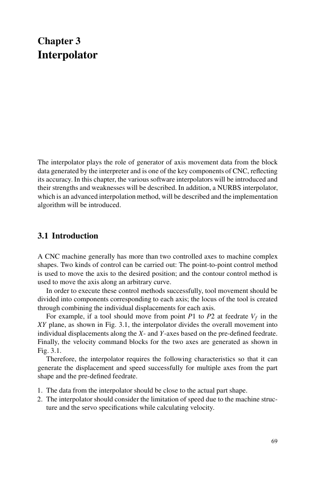
For example, if a tool should move from point P1 to P2 at feedrate Vf in the
XY plane, as shown in Fig. 3.1, the interpolator divides the overall movement into
individual displacements along the X- and Y-axes based on the pre-defined feedrate.
Finally, the velocity command blocks for the two axes are generated as shown in
Fig. 3.1.
Therefore, the interpolator requires the following characteristics so that it can
generate the displacement and speed successfully for multiple axes from the part
shape and the pre-defined feedrate.
1. The data from the interpolator should be close to the actual part shape.
2. The interpolator should consider the limitation of speed due to the machine struc-
ture and the servo specifications while calculating velocity.
69
�
70
3 Interpolator
V
v1
V
v2
Y
y2
P2
Vf
P1
x1
x2
X
Fig. 3.1 The basic concept of an interpolator
X
Y
3. The accumulation of interpolation error should be avoided in order that the final
position should coincide as closely as possible to the position commanded.
The interpolator can be classified as either a hardware interpolator or a software
interpolator by considering the implementation method. The hardware interpolator,
which consists of various electric devices, was widely used until CNC was devel-
oped. However, today, interpolators implemented using software are used in modern
CNC systems. The concept of the software interpolator originates from that of the
hardware interpolator and the hardware interpolator is limited to control simple sys-
tems.
3.2 Hardware Interpolator
The hardware interpolator carries out the computation of interpolation and generates
pulses by using an electric circuit. In the hardware interpolator, high-speed execution
is possible, but it is difficult to adapt new algorithms or modify algorithms. In NC,
the computation of interpolation and feedrate depends on hardware. However, the
dependency on hardware has been gradually decreased because of the introduction
of computer numerical control (CNC) systems.
The typical method for hardware interpolation uses a DDA(Digital Differential
Analyzer) integrator. The method using the DDA integrator is transformed into a
software version and can be applied to modern CNC. In this section, the DDA inte-
grator will be introduced and the hardware interpolation method using a DDA inte-
grator will be addressed.
�
3.2 Hardware Interpolator
71
3.2.1 Hardware Interpolation DDA
The hardware interpolator uses a DDA based on the principle of a numerical inte-
gration. A DDA is a digital circuit operated as a digital integrator that is similar to
integration by an OP amplifier in an analog circuit.
Understanding of the concept of integration should be preceded by knowledge
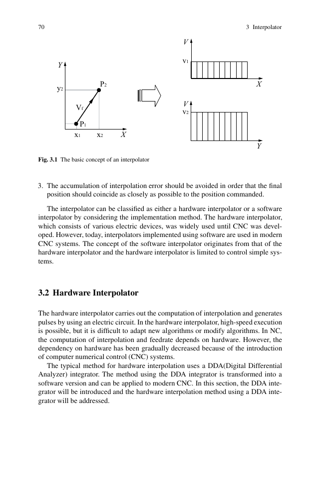
of the principle of interpolation. Given the velocity function V (t), the displacement
S(t) can be approximated by summing the areas of the thin rectangles beneath the
velocity curve as shown in Fig. 3.2.
V
V(t)
∆
∆t
t
Fig. 3.2 Velocity curve and approximating rectangles
S(t) =
t
V · dt ∼=
Vi ·Δt
k
∑
i=1
(3.1)
where, Δt stands for an iteration time interval. If the displacement at time t = k·Δt
is defined as Sk, Equation 3.1 can be rewritten as Eqs. 3.2 and 3.3.
0
Sk =
k−1
∑
i=1
Vi·Δt +Vk ·Δt
or
where ΔSk is defined in Eq. 3.4.
Sk = Sk−1 +ΔSk
ΔSk = Vk ·Δt
The following three processes are necessary for integration:
(3.2)
(3.3)
(3.4)
�
72
3 Interpolator
1. Calculate current velocity by velocity summing at the previous time unit and the
velocity increment at the current time unit by using Eq. 3.5.
Vk = Vk−1 +ΔVk
(3.5)
2. Calculate the distance increment at the current time unit using Eq. 3.4.
3. Calculate the total displacement by summing the displacement at the previous
time unit and the distance increment at the current time unit using Eq. 3.3.
f = 1
Δt
(3.6)
The above integration process is repeated for every constant time interval and the
iteration frequency is given by Eq. 3.6.
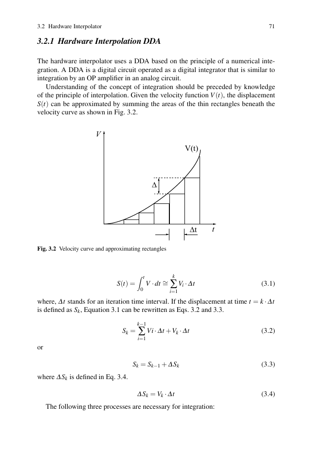
The DDA integrator as mentioned above can be realized using hardware, and the
hardware structure and representation symbol are shown in Fig. 3.3.
Iteration
clock f
n-bit binary adder
Q register
Overflow
∆S
+∆V
∆V
up/down counter
V register
+∆V
∆V
f
∆S
Fig. 3.3 DDA concept and representation symbol
The DDA integrator consists of two n-bit registers. The Q register is an n-bit
binary adder and the V register is an n-bit up/down counter. The following is the
integration process of a DDA integrator by using each component.
First, Eq. 3.5 is applied when the V register is updated by ΔV , being 0 or 1. This
is added to the lowest bit of the V register whenever the DDA integrator is iterated.
The value of the Q register and the value of the V register are summed up by binary
addition. If the value of the Q register is greater than (2n− 1), which is the maximum
value of an n-bit register, overflow occurs and this overflow becomes ΔS, which is
the output of the DDA integrator.
Because the DDA integrator itself has no function for summing ΔS, an additional
counter circuit is required in order to realize the second step of integration repre-
sented by Eq. 3.3. In mathematical form, the displacement ΔS is as in Eq. 3.7.
ΔSk = 2
−n ·Vk
(3.7)
Equation 3.7 can be written in the style of Eq.3.4 by utilizing Eq. 3.6, which gives
Eq. 3.8.
�
3.2 Hardware Interpolator
ΔSk = 2
−n·Vk · ( f ·Δt) = f
2n
·Vk ·Δt
73
(3.8)
Accordingly, the average frequency for generating ΔS can be written as Eq. 3.9.
f0 =
k
ΔS
Δt
= f
2n
·Vk
(3.9)
In the following, the bandwidth of the integration process is proportional to the
frequency, f , and the velocity, V , while it is inversely proportional to 2n. (where n is
the length of a register and determines the resolution of the integration. Therefore,
the larger the value of n, the higher the accuracy of the integration.)
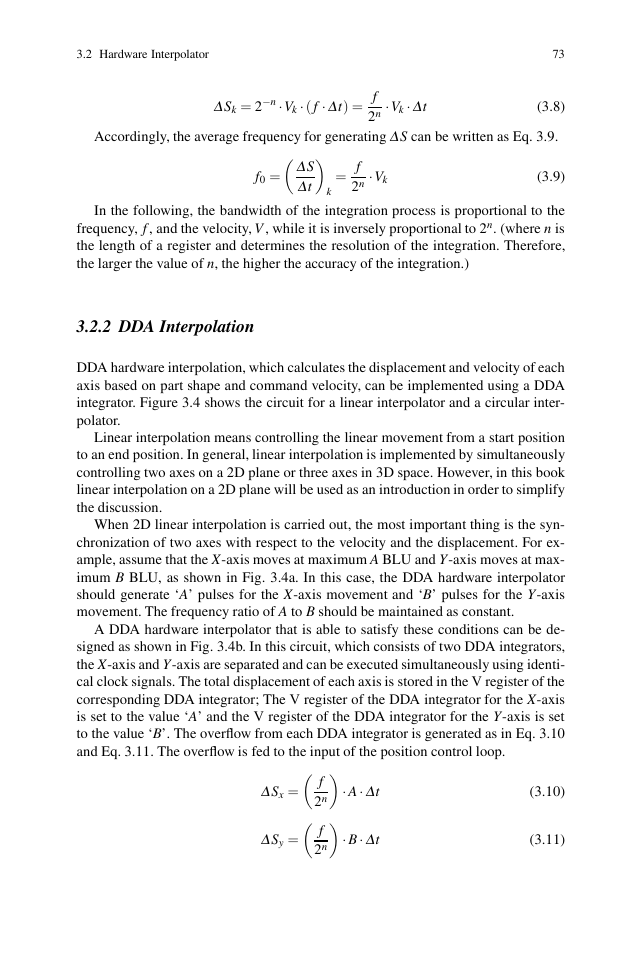
3.2.2 DDA Interpolation
DDA hardware interpolation, which calculates the displacement and velocity of each
axis based on part shape and command velocity, can be implemented using a DDA
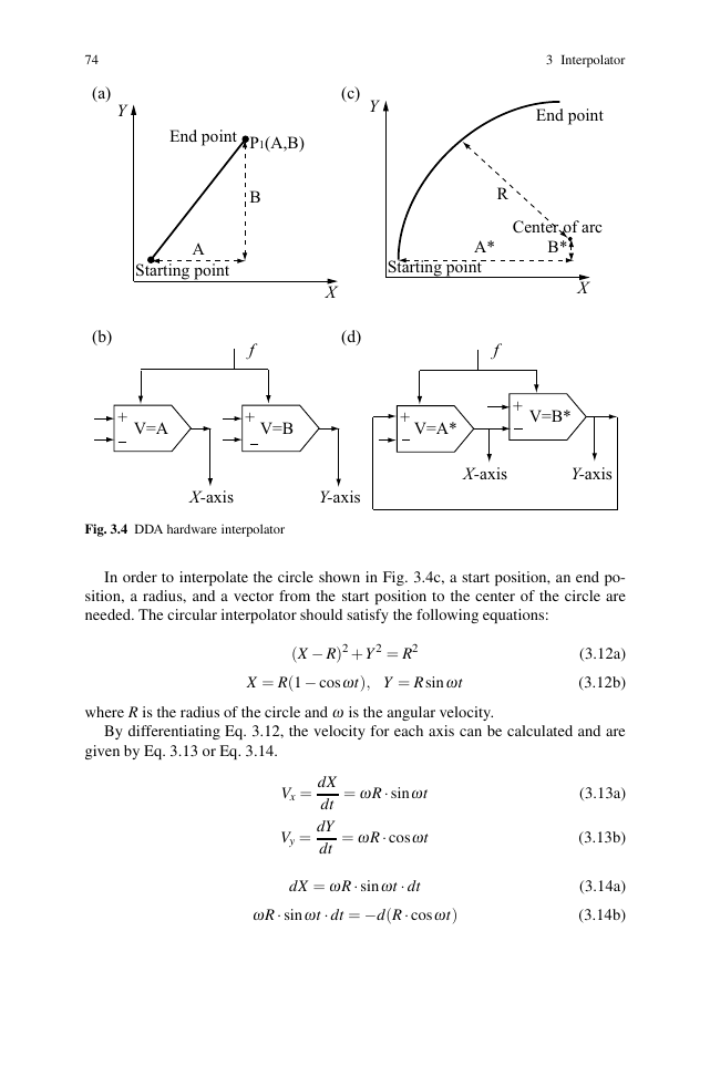
integrator. Figure 3.4 shows the circuit for a linear interpolator and a circular inter-
polator.
Linear interpolation means controlling the linear movement from a start position
to an end position. In general, linear interpolation is implemented by simultaneously
controlling two axes on a 2D plane or three axes in 3D space. However, in this book
linear interpolation on a 2D plane will be used as an introduction in order to simplify
the discussion.
When 2D linear interpolation is carried out, the most important thing is the syn-
chronization of two axes with respect to the velocity and the displacement. For ex-
ample, assume that the X-axis moves at maximum A BLU and Y-axis moves at max-
imum B BLU, as shown in Fig. 3.4a. In this case, the DDA hardware interpolator
should generate ‘A’ pulses for the X-axis movement and ‘B’ pulses for the Y-axis
movement. The frequency ratio of A to B should be maintained as constant.
A DDA hardware interpolator that is able to satisfy these conditions can be de-
signed as shown in Fig. 3.4b. In this circuit, which consists of two DDA integrators,
the X-axis and Y-axis are separated and can be executed simultaneously using identi-
cal clock signals. The total displacement of each axis is stored in the V register of the
corresponding DDA integrator; The V register of the DDA integrator for the X-axis
is set to the value ‘A’ and the V register of the DDA integrator for the Y-axis is set
to the value ‘B’. The overflow from each DDA integrator is generated as in Eq. 3.10
and Eq. 3.11. The overflow is fed to the input of the position control loop.
ΔSx =
ΔSy =
f
2n
f
2n
· A·Δt
· B·Δt
(3.10)
(3.11)
�
74
(a)
Y
(c)
Y
End point
P1(A,B)
B
f
+
V=B
X
(d)
A
Starting point
(b)
+
V=A
X-axis
Y-axis
Fig. 3.4 DDA hardware interpolator
3 Interpolator
End point
A*
Starting point
R
Center of arc
B*
X
f
+
V=A*
+
V=B*
X-axis
Y-axis
In order to interpolate the circle shown in Fig. 3.4c, a start position, an end po-
sition, a radius, and a vector from the start position to the center of the circle are
needed. The circular interpolator should satisfy the following equations:
(X − R)2 +Y 2 = R2
X = R(1− cosωt), Y = R sinωt
(3.12a)
(3.12b)
where R is the radius of the circle and ω is the angular velocity.
By differentiating Eq. 3.12, the velocity for each axis can be calculated and are
given by Eq. 3.13 or Eq. 3.14.
= ωR· sinωt
Vx = dX
dt
= ωR· cosωt
Vy = dY
dt
dX = ωR· sinωt · dt
ωR· sinωt · dt = −d(R· cosωt)
(3.13a)
(3.13b)
(3.14a)
(3.14b)
�
3.3 Software Interpolator
dY = ωR· cosωt · dt
ωR· cosωt · dt = +d(R· sinωt)
75
(3.15a)
(3.15b)
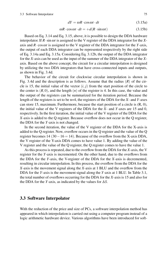
Based on Eq. 3.14 and Eq. 3.15, above, it is possible to design the DDA hardware
interpolator. If R·sinωt is assigned to the V register of the DDA integrator for the X-
axis and R· cosωt is assigned to the V register of the DDA integrator for the Y-axis,
the output of each DDA integrator can be represented respectively by the right side
of Eq. 3.14a and Eq. 3.15a. Considering Eq. 3.12b, the output of the DDA integrator
for the X-axis can be used as the input of the summer of the DDA integrator of the X-
axis. Based on the above concept, the circuit for a circular interpolation is designed
by utilizing the two DDA integrators that have cross-connected inputs and outputs,
as shown in Fig. 3.4d.
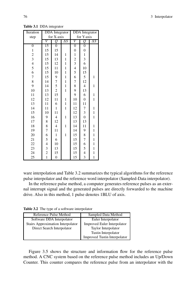
The behavior of the circuit for clockwise circular interpolation is shown in
Fig. 3.4d and the description is as follows. Assume that the radius (R) of the cir-
cle is 15, the initial value of the vector (i, j) from the start position of the circle to
the center is (R,0), and the length (n) of the register is 4. In this case, the value and
the output of the registers can be summarized for the iteration period. Because the
length of the registers is set to be n=4, the registers of the DDA for the X- and Y-axes
can store 15, maximum. Furthermore, because the start position of a circle is (R, 0),
the initial value of the V registers of the DDA for the X- and Y-axes are 15 and 0,
respectively. In the first iteration, the initial value of the V register of the DDA for the
X-axis is added to the Q register. Because overflow does not occur in the Q register,
the DDA for the Y-axis is not changed.
In the second iteration, the value of the V register of the DDA for the X-axis is
added to the Q register. Now, overflow occurs in the Q register and the value of the Q
register becomes 14 (30− 16 = 14). Because of the overflow from the X-axis DDA,
the V register of the Y-axis DDA comes to have value 1. By adding the value of the
V register and the value of the Q register, the Q register comes to have the value 1.
As this process is repeated, due to the overflow from the DDA for the X-axis, the V
register for the Y-axis is incremented. On the other hand, due to the overflows from
the DDA for the Y-axis, the V-register of the DDA for the X-axis is decremented,
resulting in circular interpolation. In this process, the overflow from the DDA for the
X-axis is the movement signal along the X-axis at 1 BLU and the overflow from the
DDA for the Y-axis is the movement signal along the Y-axis at 1 BLU. In Table 3.1,
the total number of overflows occurring for the DDA for the X-axis is 15 and also for
the DDA for the Y-axis, as indicated by the values for ΔS.
3.3 Software Interpolator
With the reduction of the price and size of PCs, a software interpolation method has
appeared in which interpolation is carried out using a computer program instead of a
logic arithmetic hardware device. Various algorithms have been introduced for soft-
�
76
3 Interpolator
Table 3.1 DDA integrator
Iteration
DDA Integrator DDA Integrator
for X-axis
for Y-axis
1
1
1
1
1
1
1
1
1
Q ΔS
0
15
14
13
12
11
10
9
7
5
2
15
11
6
1
11
4
12
4
11
1
6
10
13
15
0
1
1
1
1
1
1
V
0
0
1
2
3
4
5
6
7
8
9
9
10
11
12
12
13
13
14
14
15
15
15
15
15
15
1
1
1
1
Q ΔS
0
0
1
3
6
10
15
5
12
4
13
6
0
11
7
3
0
13
11
9
8
7
6
5
4
3
1
1
1
1
1
1
1
1
1
1
1
step
0
1
2
3
4
5
6
7
8
9
10
11
12
13
14
15
16
17
18
19
20
21
22
23
24
25
V
15
15
15
15
15
15
15
15
14
14
13
13
12
11
11
10
9
8
8
7
6
5
4
3
2
1
ware interpolation and Table 3.2 summarizes the typical algorithms for the reference
pulse interpolator and the reference word interpolator (Sampled-Data interpolator).
In the reference pulse method, a computer generates reference pulses as an exter-
nal interrupt signal and the generated pulses are directly forwarded to the machine
drive. Also in this method, 1 pulse denotes 1BLU of axis.
Table 3.2 The type of a software interpolator
Reference Pulse Method
Software DDA Interpolator
Sampled Data Method
Euler Interpolator
Stairs Approximation Interpolator
Improved Euler Interpolator
Direct Search Interpolator
Taylor Interpolator
Tustin Interpolator
Improved Tustin Interpolator
Figure 3.5 shows the structure and information flow for the reference pulse
method. A CNC system based on the reference pulse method includes an Up/Down
Counter. This counter compares the reference pulse from an interpolator with the
�


 2023年江西萍乡中考道德与法治真题及答案.doc
 2012年重庆南川中考生物真题及答案.doc
 2013年江西师范大学地理学综合及文艺理论基础考研真题.doc
 2020年四川甘孜小升初语文真题及答案I卷.doc
 2020年注册岩土工程师专业基础考试真题及答案.doc
 2023-2024学年福建省厦门市九年级上学期数学月考试题及答案.doc
 2021-2022学年辽宁省沈阳市大东区九年级上学期语文期末试题及答案.doc
 2022-2023学年北京东城区初三第一学期物理期末试卷及答案.doc
 2018上半年江西教师资格初中地理学科知识与教学能力真题及答案.doc
 2012年河北国家公务员申论考试真题及答案-省级.doc
 2020-2021学年江苏省扬州市江都区邵樊片九年级上学期数学第一次质量检测试题及答案.doc
 2022下半年黑龙江教师资格证中学综合素质真题及答案.doc